EP0718158A1 - Stossstange mit Halterungen zum Befestigen an einem Fahrzeug - Google Patents
Stossstange mit Halterungen zum Befestigen an einem Fahrzeug Download PDFInfo
- Publication number
- EP0718158A1 EP0718158A1 EP95810777A EP95810777A EP0718158A1 EP 0718158 A1 EP0718158 A1 EP 0718158A1 EP 95810777 A EP95810777 A EP 95810777A EP 95810777 A EP95810777 A EP 95810777A EP 0718158 A1 EP0718158 A1 EP 0718158A1
- Authority
- EP
- European Patent Office
- Prior art keywords
- wedge
- bumper
- support part
- shaped support
- vehicle
- Prior art date
- Legal status (The legal status is an assumption and is not a legal conclusion. Google has not performed a legal analysis and makes no representation as to the accuracy of the status listed.)
- Granted
Links
- 229910000838 Al alloy Inorganic materials 0.000 claims description 3
- 229910001092 metal group alloy Inorganic materials 0.000 claims description 3
- 230000006835 compression Effects 0.000 abstract description 2
- 238000007906 compression Methods 0.000 abstract description 2
- 230000003116 impacting effect Effects 0.000 description 3
- 238000010586 diagram Methods 0.000 description 2
- 230000014759 maintenance of location Effects 0.000 description 2
- 229910052782 aluminium Inorganic materials 0.000 description 1
- XAGFODPZIPBFFR-UHFFFAOYSA-N aluminium Chemical compound [Al] XAGFODPZIPBFFR-UHFFFAOYSA-N 0.000 description 1
- 239000011324 bead Substances 0.000 description 1
- 230000015572 biosynthetic process Effects 0.000 description 1
- 230000006378 damage Effects 0.000 description 1
- 230000001419 dependent effect Effects 0.000 description 1
- 238000006073 displacement reaction Methods 0.000 description 1
- 238000004519 manufacturing process Methods 0.000 description 1
- 238000000034 method Methods 0.000 description 1
- 230000035939 shock Effects 0.000 description 1
Images


Classifications
-
- B—PERFORMING OPERATIONS; TRANSPORTING
- B60—VEHICLES IN GENERAL
- B60R—VEHICLES, VEHICLE FITTINGS, OR VEHICLE PARTS, NOT OTHERWISE PROVIDED FOR
- B60R19/00—Wheel guards; Radiator guards, e.g. grilles; Obstruction removers; Fittings damping bouncing force in collisions
- B60R19/02—Bumpers, i.e. impact receiving or absorbing members for protecting vehicles or fending off blows from other vehicles or objects
- B60R19/24—Arrangements for mounting bumpers on vehicles
-
- B—PERFORMING OPERATIONS; TRANSPORTING
- B60—VEHICLES IN GENERAL
- B60R—VEHICLES, VEHICLE FITTINGS, OR VEHICLE PARTS, NOT OTHERWISE PROVIDED FOR
- B60R19/00—Wheel guards; Radiator guards, e.g. grilles; Obstruction removers; Fittings damping bouncing force in collisions
- B60R19/02—Bumpers, i.e. impact receiving or absorbing members for protecting vehicles or fending off blows from other vehicles or objects
- B60R19/18—Bumpers, i.e. impact receiving or absorbing members for protecting vehicles or fending off blows from other vehicles or objects characterised by the cross-section; Means within the bumper to absorb impact
- B60R2019/1806—Structural beams therefor, e.g. shock-absorbing
- B60R2019/1813—Structural beams therefor, e.g. shock-absorbing made of metal
- B60R2019/182—Structural beams therefor, e.g. shock-absorbing made of metal of light metal, e.g. extruded
Definitions
- the invention relates to a bumper with brackets attached to it for fastening to a vehicle, in particular to a passenger car, the bumper being arched at least in the area of the brackets relative to the front line of the vehicle and with profile walls arranged at a distance from one another as a compression belt or tension belt and a pair of transverse walls connecting them forms a hollow profile.
- connection to the vehicle side member also influences its shape retention and its ability to compensate for the deformation energy that occurs.
- a large number of brackets are known for fastening the bumper to the vehicle, but they hardly contribute to improving the shape of a bumper in the event of an impact.
- the inventor has set himself the task of creating a bumper with brackets of the type mentioned at the outset, which, while being light in weight, has a high degree of shape retention with sufficient compensation for the impacting deformation energy.
- the manufacture and handling of the bumper and the brackets should be very simple.
- the brackets have a wedge-shaped support part which lies with the wedge bevel against the tension belt and is connected to it in the region of the highest point of the wedge bevel.
- the brackets have a bracket plate which can be fixed to the vehicle side members and from which the wedge-shaped support part is integrally formed.
- the wedge-shaped support part is expediently connected to the tension belt by means of screws or rivets.
- the width of the tension belt projects beyond the width of the wedge slope of the wedge-shaped support part, which is adjacent to the tension belt, by one dimension.
- Bumpers as well as brackets are preferably made of a light metal alloy, in particular an aluminum alloy, the bumper being extruded as a profile.
- the angle between the wedge slope of the wedge-shaped support part and the front line of the vehicle is preferably between 5 and 25 °, in particular between about 5 and 15 °.
- the vertical projection line p of the area A of the highest point of the wedge bevel on the front line F is preferably within a longitudinal member.
- the bumper 10 is extruded as an aluminum profile and bulges by a dimension t in the center relative to an imaginary front line F of the passenger car.
- the bumper 10 has two spaced apart profile walls 12, 14, which are supplemented by transverse walls 16, 18 to form a box-shaped hollow profile.
- the profile wall 12 pointing away from the vehicle corresponds to the outer belt or pressure belt receiving a shock
- the profile wall 14 directed against the vehicle corresponds to the inner belt or tension belt.
- a crossbar 20 connecting the profile walls 12, 14 is arranged centrally between the two transverse walls 16, 18.
- the holder 22 has a holder plate 32 which, in the installed position, is screwed to the vehicle side member 24 via diagonally arranged bores 34.
- a wedge-shaped support part 26 is formed from the holder plate 32 to form a cavity 27. This wedge-shaped support part 26 lies with its wedge bevel 30 against the tension belt 14 and is connected in area A of the highest point of the support part 26 via a rivet 28 to the tension belt 14. It is important here for reasons of stability during an impact that the vertical projection line p of the area A onto the front line F within of the longitudinal beam 24.
- the wedge bevel 30 forms an angle ⁇ of, for example, 10 ° with the imaginary front line F, which runs perpendicular to the vehicle longitudinal direction x.
- the smaller width e of the wedge-shaped support part 26 compared to the width b Z of the tension belt 14 of the bumper 10 has the consequence that the bumper 10 deforms like a clip around the support part 26 with the formation of beads 38.
- the partial encirclement of the support part 26 by the partially deforming bumper 10 results in a stability which counteracts the torsion of the bumper 10, increases its dimensional stability and improves the overall compensation capacity for the impacting deformation energy.
- the force-path diagram according to FIG. 6 shows the dependence of the compressive force P (kN) on the deflection path s (mm) as a result a stress test carried out on a bumper arrangement according to the invention.
- the course of the curve indicates the excellent compensation capacity for the impacting deformation energy.
Landscapes
- Engineering & Computer Science (AREA)
- Mechanical Engineering (AREA)
- Body Structure For Vehicles (AREA)
Abstract
Description
- Die Erfindung betrifft eine Stossstange mit an dieser festgelegten Halterungen zum Befestigen an einem Fahrzeug, insbesondere an einem Personenkraftwagen, wobei die Stossstange zumindest im Bereich der Halterungen gegenüber der Frontlinie des Fahrzeugs gewölbt ausgebildet ist und mit in Abstand zueinander als Druckgurt bzw. Zuggurt angeordneten Profilwänden sowie einem Paar sie verbindender Querwände ein Hohlprofil bildet.
- Neben der Querschnittsform der Stossstange beeinflusst auch die Ausgestaltung der Verbindung zum Fahrzeuglängsträger deren Formhaltigkeit sowie deren Kompensationsvermögen für die auftreffende Verformungsenergie.
- Zur Befestigung der Stossstange am Fahrzeug sind eine Vielzahl von Halterungen bekannt, die jedoch kaum zur Verbesserung der Formhaltigkeit einer Stossstange bei einem Aufprall beitragen.
- Angesichts dieser Gegebenheiten hat sich der Erfinder die Aufgabe gestellt, eine Stossstange mit an dieser festgelegten Halterungen der eingangs erwähnten Art zu schaffen, die bei geringem Gewicht ein hohes Mass an Formhaltigkeit bei ausreichendem Kompensationsvermögen für die auftreffende Verformungsenergie aufweist. Zudem sollen Herstellung und Handhabung der Stossstange sowie der Halterungen sehr einfach sein.
- Zur erfindungsgemässen Lösung der Aufgabe führt, dass die Halterungen ein keilförmiges Stützteil aufweisen, das mit seiner Keilschräge dem Zuggurt anliegt und mit diesem im Bereich des höchsten Punktes der Keilschräge verbunden ist.
- Die erfindungsgemässe Stossstangenanordnung weiterbildende Merkmale sind Gegenstand von abhängigen Patentansprüchen.
- Bei einer bevorzugten Ausführungsform der erfindungsgemässen Stossstange weisen die Halterungen eine an Fahrzeuglängsträgern festlegbare Halterplatte auf, aus welcher das keilförmige Stützteil integral ausgeformt ist.
- Die Verbindung des keilförmigen Stützteils mit dem Zuggurt erfolgt zweckmässigerweise über Schrauben oder Nieten.
- Bei einer besonders bevorzugten Ausführungsform der erfindungsgemässen Stossstangenanordnung überragt die Breite des Zuggurts die Breite der dem Zuggurt anliegenden Keilschräge des keilförmigen Stützteils beidseits um ein Mass.
- Stossstange wie auch Halterungen sind bevorzugt aus einer Leichtmetallegierung insbesondere aus einer Aluminiumlegierung gefertigt, wobei die Stossstange als Profil stranggepresst ist.
- Der Winkel zwischen der Keilschräge des keilförmigen Stützteils und der Frontlinie des Fahrzeugs liegt bevorzugt zwischen 5 und 25°, insbesondere zwischen etwa 5 und 15°.
- Aus Stabilitätsgründen während eines Aufpralls liegt die senkrechte Projektionslinie p des Bereichs A des höchsten Punktes der Keilschräge auf die Frontlinie F bevorzugt innerhalb eines Längsträgers.
- Weitere Vorteile, Merkmale und Einzelheiten der Erfindung ergeben sich aus der nachfolgenden Beschreibung eines bevorzugten Ausführungsbeispiels sowie anhand der Zeichnung; diese zeigt schematisch in
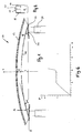
- Fig. 1 die Draufsicht auf eine Stossstange;
- Fig. 2 den Querschnitt durch die Stossstange von Fig. 1 nach deren Linie I-I;
- Fig. 3 ein vergrössertes Detail von Fig, 1 im Bereich einer Halterung;
- Fig. 4 eine Schrägsicht auf die Unterseite der Halterung von Fig. 3;
- Fig. 5a-c die Verformung der Stossstange im Bereich der Halterung;
- Fig. 6 ein Kraft-Weg Diagramm zu Belastungsversuchen.
- Eine in Fig. 1 dargestellte Stossstange 10 eines aus Gründen der besseren Uebersicht nicht wiedergegebenen Personenkraftwagens ist über Halterungen 22 an Fahrzeuglängsträgern 24 befestigt. Die Stossstange 10 ist als Aluminiumprofil stranggepresst und gegenüber einer gedachten Frontlinie F des Personenkraftwagens mittig um ein Mass t ausgebaucht.
- Die Stossstange 10 weist gemäss Fig. 1 und 2 zwei in Abstand 1 zueinander stehende Profilwände 12, 14 auf, die durch Querwände 16, 18 zu einem kastenförmigen Hohlprofil ergänzt sind. In Einbaulage entspricht die vom Fahrzeug wegweisende Profilwand 12 dem einen Stoss aufnehmenden Aussengurt bzw. Druckgurt, die gegen das Fahrzeug gerichtete Profilwand 14 dem Innengurt bzw. Zuggurt. Mittig zwischen den beiden Querwänden 16, 18 ist ein die Profilwände 12, 14 verbindender Quersteg 20 angeordnet.
- Wie insbesondere aus Fig. 3 und 4 hervorgeht, weist die Halterung 22 eine Halterplatte 32 auf, die in Einbaulage über diagonal angeordnete Bohrungen 34 mit dem Fahrzeuglängsträger 24 verschraubt ist. Aus der Halterplatte 32 ist unter Bildung eines Hohlraumes 27 ein keilförmiges Stützteil 26 ausgeformt. Dieses keilförmige Stützteil 26 liegt mit seiner Keilschräge 30 dem Zuggurt 14 an und ist im Bereich A des höchsten Punktes des Stützteils 26 über eine Niete 28 mit dem Zuggurt 14 verbunden. Hierbei ist aus Stabilitätsgründen während eines Aufpralls von Bedeutung, dass die senkrechte Projektionslinie p des Bereichs A auf die Frontlinie F innerhalb des Längsträgers 24 liegt.
- Die Keilschräge 30 bildet mit der gedachten Frontlinie F, die senkrecht zur Fahrzeuglängsrichtung x verläuft, einen Winkel α von beispielsweise 10°.
- Aus Fig. 4 ist ersichtlich. dass die Breite bZ des Zuggurtes 14 die Breite e des keilförmigen Stützteils 26 bzw. der Keilschräge 30 beidseits um ein Mass a überragt. Die Bedeutung dieser speziellen Anordnung ergibt sich aus der Betrachtung des in Fig. 5a bis c schematisch dargestellten Verformungsablaufs der Stossstange 10 im Bereich der Halterung 22.
- Bei der Einwirkung einer frontalen Kraft P auf die Stossstange 10 wird diese zunächst in einer ersten Stufe der Verformung gerade gerichtet, d.h. es erfolgt eine Drehung um eine Achse im Bereich A des höchsten Punktes der Keilschräge 30, wodurch sich der Zuggurt 14 von der Keilschräge 30 abhebt. Der Bereich A bildet nunmehr die alleinige Auflagefläche für die Stossstange 10 (Fig. 5a). Im nachfolgenden, in Fig. 5b, c (Fig. 5c zeigt den Querschnitt von Fig. 5b nach deren Linie II-II) dargestellten zweiten Verformungsschritt erfolgt die eigentliche Verformung der Stossstange 10 und damit die Vernichtung des grössten Teils der Aufprallenergie. Wie insbesondere aus Fig. 5c hervorgeht, hat die kleinere Breite e des keilförmigen Stützteils 26 gegenüber der Breite bZ des Zuggurtes 14 der Stossstange 10 zur Folge, dass sich die Stossstange 10 unter Ausbildung von Wulsten 38 klammerartig um das Stützteil 26 verformt. Aus der teilweisen Umschliessung des Stützteils 26 durch die sich teilweise verformende Stossstange 10 resultiert eine Stabilität, die der Verwindung der Stossstange 10 entgegenwirkt, deren Formhaltigkeit erhöht und insgesamt das Kompensationsvermögen für die auftreffende Verformungsenergie verbessert.
- Das Kraft-Weg Diagramm nach Fig. 6 zeigt die Abhängigkeit der Druckkraft P (kN) vom Durchbiegungsweg s (mm) als Ergebnis eines an einer erfindungsgemässen Stossstangenanordnung durchgeführten Belastungstestes. Der Kurvenverlauf weist auf das ausgezeichnete Kompensationsvermögen für die auftreffende Verformungsenergie hin.
Claims (8)
- Stossstange mit an dieser festgelegten Halterungen zum Befestigen an einem Fahrzeug, insbesondere an einem Personenkraftwagen, wobei die Stossstange zumindest im Bereich der Halterungen (22) gegenüber der Frontlinie (F) des Fahrzeugs gewölbt ausgebildet ist und mit in Abstand (1) zueinander als Druckgurt (12) bzw. Zuggurt (14) angeordneten Profilwänden (12,14) sowie einem Paar sie verbindender Querwände (16,18) ein Hohlprofil bildet,
dadurch gekennzeichnet,
dass die Halterungen (22) ein keilförmiges Stützteil (26) aufweisen, das mit seiner Keilschräge (30) dem Zuggurt (14) anliegt und mit diesem im Bereich (A) des höchsten Punktes der Keilschräge (30) verbunden ist. - Stossstange nach Anspruch 1, dadurch gekennzeichnet, dass die Halterungen (22) eine an Fahrzeuglängsträgern (24) festlegbare Halterplatte (32) aufweisen, aus welcher das keilförmige Stützteil (26) integral ausgeformt ist.
- Stossstange nach Anspruch 1 oder 2, dadurch gekennzeichnet, dass das keilförmige Stützteil (26) mit dem Zuggurt (12) verschraubt oder vernietet ist.
- Stossstange nach einem der Ansprüche 1 bis 3, dadurch gekennzeichnet, dass die Breite (bZ) des Zuggurts (14) die Breite (e) der dem Zuggurt (14) anliegenden Keilschräge (30) des keilförmigen Stützteils (26) beidseits um ein Mass (a) überragt.
- Stossstange nach einem der Ansprüche 1 bis 4, dadurch gekennzeichnet, dass sie aus einem stranggepressten Profil aus einer Leichtmetallegierung, insbesondere aus einer Aluminiumlegierung besteht.
- Stossstange nach einem der Ansprüche 1 bis 5, dadurch gekennzeichnet, dass die Halterungen (22) aus einer Leichtmetallegierung, insbesondere aus einer Aluminiumlegierung, gefertigt sind.
- Stossstange nach einem der Ansprüche 1 bis 6, dadurch gekennzeichnet, dass der Winkel (α) zwischen der Keilschräge (30) des keilförmigen Stützteils (26) und der Frontlinie (F) des Fahrzeugs 5 bis 25°, insbesondere 5 bis 15°, beträgt.
- Stossstange nach einem der Ansprüche 1 bis 7, dadurch gekennzeichnet, dass die senkrechte Projektionslinie (p) des Bereichs (A) des höchsten Punktes der Keilschräge (30) auf die Frontlinie (F) innerhalb eines Längsträgers (24) liegt.
Applications Claiming Priority (2)
| Application Number | Priority Date | Filing Date | Title |
|---|---|---|---|
| CH03928/94A CH688652A5 (de) | 1994-12-23 | 1994-12-23 | Stossstange mit Halterungen zum Befestigen an einem Fahrzeug. |
| CH3928/94 | 1994-12-23 |
Publications (2)
| Publication Number | Publication Date |
|---|---|
| EP0718158A1 true EP0718158A1 (de) | 1996-06-26 |
| EP0718158B1 EP0718158B1 (de) | 1998-11-25 |
Family
ID=4266509
Family Applications (1)
| Application Number | Title | Priority Date | Filing Date |
|---|---|---|---|
| EP95810777A Expired - Lifetime EP0718158B1 (de) | 1994-12-23 | 1995-12-08 | Stossstange mit Halterungen zum Befestigen an einem Fahrzeug |
Country Status (5)
| Country | Link |
|---|---|
| US (1) | US5584518A (de) |
| EP (1) | EP0718158B1 (de) |
| JP (1) | JP3059925B2 (de) |
| CH (1) | CH688652A5 (de) |
| DE (1) | DE59504331D1 (de) |
Cited By (7)
| Publication number | Priority date | Publication date | Assignee | Title |
|---|---|---|---|---|
| WO1999015365A1 (en) * | 1997-09-22 | 1999-04-01 | Norsk Hydro Asa | Bumper, and the fabrication thereof |
| DE10128114A1 (de) * | 2001-03-28 | 2002-10-10 | Wagon Automotive Gmbh | Aufpralldämpfer |
| WO2005016725A1 (de) * | 2003-08-07 | 2005-02-24 | Daimlerchrysler Ag | Fahrerhaus für ein nutzfahrzeug |
| US6932398B2 (en) | 2002-03-06 | 2005-08-23 | Alcan Technology & Management Ltd. | Bumper having a hollow section and mounting brackets attached to it |
| US7401825B2 (en) | 2005-04-27 | 2008-07-22 | Alcan Technology & Management Ltd. | Bumper with attachment means |
| US8246092B2 (en) | 2006-04-25 | 2012-08-21 | GM Global Technology Operations LLC | Profiled element for fastening a bumper to longitudinal beams of a vehicle, and method therefor |
| US8454064B2 (en) | 2006-04-25 | 2013-06-04 | GM Global Technology Operations LLC | Arrangement and method for attaching a bumper to side members of a vehicle |
Families Citing this family (22)
| Publication number | Priority date | Publication date | Assignee | Title |
|---|---|---|---|---|
| JP3120957B2 (ja) * | 1995-07-07 | 2000-12-25 | 本田技研工業株式会社 | 車両用バンパビームの製造方法 |
| JP3550999B2 (ja) * | 1998-01-20 | 2004-08-04 | 日産自動車株式会社 | 車両のバンパー取付け構造 |
| US6042163A (en) * | 1998-01-28 | 2000-03-28 | Shape Corporation | Vehicle bumper including end section and method of manufacture |
| US6174009B1 (en) | 1998-10-09 | 2001-01-16 | Shape Corporation | Bumper construction including self-orienting support towers providing consistent energy absorption on impact |
| US6179353B1 (en) | 1999-07-27 | 2001-01-30 | Shape Corporation | High flex bumper with reinforced corner end sections |
| US6601474B2 (en) * | 2000-09-05 | 2003-08-05 | Kanzaki Kokyukoki Mfg. Co., Ltd. | Hydrostatic transmission and power train for vehicle |
| US6975915B2 (en) * | 2002-10-31 | 2005-12-13 | Sap Ag | Cooperative smart items |
| US6979030B2 (en) * | 2002-11-05 | 2005-12-27 | Hud-Marsh Golf Products | Golf car bumper |
| JP4219189B2 (ja) * | 2003-02-28 | 2009-02-04 | 株式会社アステア | 車体メンバに対するバンパ補強材の支持構造 |
| US8496258B2 (en) * | 2003-10-20 | 2013-07-30 | Magna International Inc. | Hybrid component |
| US7073831B2 (en) * | 2004-06-23 | 2006-07-11 | Netshape International Llc | Bumper with crush cones and energy absorber |
| DE102006019653B4 (de) * | 2005-04-27 | 2016-03-31 | Daimler Ag | Stoßstange mit Halterungen |
| JP4723948B2 (ja) * | 2005-08-05 | 2011-07-13 | アイシン精機株式会社 | 車両用バンパリィンフォース |
| ITTO20050816A1 (it) * | 2005-11-18 | 2007-05-19 | Fiat Auto Spa | Struttura per l'assorbimento dell'energia d'urto per un veicolo particolarmente per urti frontali ad angolo variabile |
| DE102007033764B4 (de) | 2006-07-19 | 2020-06-10 | Constellium Switzerland Ag | Stoßstange mit Halterungen |
| DE102007011385A1 (de) | 2007-03-07 | 2008-09-11 | Alcan Technology & Management Ag | Stoßstange mit Halterungen |
| DE102008030215A1 (de) | 2008-02-15 | 2009-08-27 | Alcan Technology & Management Ag | Deformationsorgan mit Halterung sowie Verfahren dazu |
| JP5140149B2 (ja) * | 2008-03-05 | 2013-02-06 | 日軽金アクト株式会社 | バンパー構造 |
| JP5180950B2 (ja) * | 2009-12-21 | 2013-04-10 | 株式会社神戸製鋼所 | バンパー構造体 |
| CN105102277B (zh) * | 2013-04-05 | 2017-10-13 | 肯联铝业辛根有限责任公司 | 将保险杠横梁安装到车辆结构上的附接装置 |
| DE102013208144A1 (de) * | 2013-05-03 | 2014-11-06 | Bayerische Motoren Werke Aktiengesellschaft | Kraftfahrzeugkarosserie |
| US10328879B2 (en) * | 2017-06-30 | 2019-06-25 | Honda Motor Co., Ltd. | Bumper bean design for crash signal separation |
Citations (5)
| Publication number | Priority date | Publication date | Assignee | Title |
|---|---|---|---|---|
| US3850466A (en) * | 1972-08-14 | 1974-11-26 | A Yepis | Vehicle bumper and frame mounting |
| US4563028A (en) * | 1982-07-01 | 1986-01-07 | Aisin Seiki Kabushiki Kaisha | Reinforcement member for a vehicle bumper |
| US5080410A (en) * | 1991-04-22 | 1992-01-14 | Chrysler Corporation | Vehicle bumper beam |
| JPH05246289A (ja) * | 1991-03-12 | 1993-09-24 | Suzuki Motor Corp | 合成樹脂製バンパー |
| JPH06211090A (ja) * | 1993-01-18 | 1994-08-02 | Toyota Motor Corp | 自動車のバンパリィインフォースの車体側の部材への取付け構造 |
Family Cites Families (6)
| Publication number | Priority date | Publication date | Assignee | Title |
|---|---|---|---|---|
| US1501191A (en) * | 1923-11-20 | 1924-07-15 | J H Sager Company | Bumper for vehicles |
| US1534010A (en) * | 1924-06-07 | 1925-04-14 | Feiner Israel | Automobile bumper |
| US2954256A (en) * | 1953-04-24 | 1960-09-27 | Daimler Benz Ag | Automobile bumper |
| FR2161174A5 (de) * | 1971-11-16 | 1973-07-06 | Cegedur | |
| US3907351A (en) * | 1973-03-21 | 1975-09-23 | Audi Ag | Impact-damping system for automotive vehicles |
| JP2779852B2 (ja) * | 1989-12-06 | 1998-07-23 | スズキ株式会社 | 合成樹脂製バンパー |
-
1994
- 1994-12-23 CH CH03928/94A patent/CH688652A5/de not_active IP Right Cessation
-
1995
- 1995-11-17 US US08/560,430 patent/US5584518A/en not_active Expired - Lifetime
- 1995-12-08 DE DE59504331T patent/DE59504331D1/de not_active Expired - Lifetime
- 1995-12-08 EP EP95810777A patent/EP0718158B1/de not_active Expired - Lifetime
- 1995-12-19 JP JP7330584A patent/JP3059925B2/ja not_active Expired - Fee Related
Patent Citations (5)
| Publication number | Priority date | Publication date | Assignee | Title |
|---|---|---|---|---|
| US3850466A (en) * | 1972-08-14 | 1974-11-26 | A Yepis | Vehicle bumper and frame mounting |
| US4563028A (en) * | 1982-07-01 | 1986-01-07 | Aisin Seiki Kabushiki Kaisha | Reinforcement member for a vehicle bumper |
| JPH05246289A (ja) * | 1991-03-12 | 1993-09-24 | Suzuki Motor Corp | 合成樹脂製バンパー |
| US5080410A (en) * | 1991-04-22 | 1992-01-14 | Chrysler Corporation | Vehicle bumper beam |
| JPH06211090A (ja) * | 1993-01-18 | 1994-08-02 | Toyota Motor Corp | 自動車のバンパリィインフォースの車体側の部材への取付け構造 |
Non-Patent Citations (2)
| Title |
|---|
| PATENT ABSTRACTS OF JAPAN vol. 17, no. 709 (M - 1535) 24 December 1993 (1993-12-24) * |
| PATENT ABSTRACTS OF JAPAN vol. 18, no. 576 (M - 1697) 4 November 1994 (1994-11-04) * |
Cited By (8)
| Publication number | Priority date | Publication date | Assignee | Title |
|---|---|---|---|---|
| WO1999015365A1 (en) * | 1997-09-22 | 1999-04-01 | Norsk Hydro Asa | Bumper, and the fabrication thereof |
| DE10128114A1 (de) * | 2001-03-28 | 2002-10-10 | Wagon Automotive Gmbh | Aufpralldämpfer |
| DE10128114B4 (de) * | 2001-03-28 | 2006-12-28 | Wagon Automotive Gmbh | Aufpralldämpfer |
| US6932398B2 (en) | 2002-03-06 | 2005-08-23 | Alcan Technology & Management Ltd. | Bumper having a hollow section and mounting brackets attached to it |
| WO2005016725A1 (de) * | 2003-08-07 | 2005-02-24 | Daimlerchrysler Ag | Fahrerhaus für ein nutzfahrzeug |
| US7401825B2 (en) | 2005-04-27 | 2008-07-22 | Alcan Technology & Management Ltd. | Bumper with attachment means |
| US8246092B2 (en) | 2006-04-25 | 2012-08-21 | GM Global Technology Operations LLC | Profiled element for fastening a bumper to longitudinal beams of a vehicle, and method therefor |
| US8454064B2 (en) | 2006-04-25 | 2013-06-04 | GM Global Technology Operations LLC | Arrangement and method for attaching a bumper to side members of a vehicle |
Also Published As
| Publication number | Publication date |
|---|---|
| CH688652A5 (de) | 1997-12-31 |
| US5584518A (en) | 1996-12-17 |
| JPH08216807A (ja) | 1996-08-27 |
| DE59504331D1 (de) | 1999-01-07 |
| EP0718158B1 (de) | 1998-11-25 |
| JP3059925B2 (ja) | 2000-07-04 |
Similar Documents
| Publication | Publication Date | Title |
|---|---|---|
| EP0718158B1 (de) | Stossstange mit Halterungen zum Befestigen an einem Fahrzeug | |
| DE10234438B4 (de) | Stoßfängeraufhängung für Fahrzeuge | |
| DE102017118515B3 (de) | Fahrzeuglängsträgeranordnung | |
| EP1132263B1 (de) | Kotflügelanordnung für ein Kraftfahrzeug | |
| DE102004001671B4 (de) | Halterungsbefestigungsaufbau | |
| EP1342625B1 (de) | Stossstange mit Halterungen | |
| EP0798197A1 (de) | Frondmodul für Kraftfahrzeuge | |
| EP0718157A1 (de) | Stossstange für Fahrzeuge | |
| DE19907783B4 (de) | Schutzvorrichtung für Kraftfahrzeuge | |
| CH691731A5 (de) | Fahrzeug mit Stossstange und Deformationselement. | |
| DE2313588A1 (de) | Bodenrahmen fuer kraftfahrzeuge | |
| EP1000840A2 (de) | Tragstruktur eines Vorderwagens eines Kraftfahrzeugs | |
| DE19603954C2 (de) | Prallträger für ein Kraftfahrzeug | |
| DE60005737T2 (de) | Stossfängeranordnung für Fahrzeuge | |
| DE69313214T2 (de) | Struktur zur Energieaufnahme, insbesondere für Eisenbahnfahrzeuge | |
| DE2308825C3 (de) | Fahrzeugkarosserie | |
| EP0517867A1 (de) | Tragstruktur einer karosserie eines personenkraftwagens. | |
| DE3942794C2 (de) | ||
| DE102020214189A1 (de) | Anordnung mit einem Stoßfängerquerträger und einem Stoßabsorberelement | |
| DE10040649C1 (de) | Überrollschutzsystem | |
| DE602005005662T2 (de) | Frontstruktur eines kraftfahrzeuges | |
| DE102018101775A1 (de) | Kotflügelhalterungsanordnung | |
| DE102008016057A1 (de) | Aufstieg für einen Lastkraftwagen | |
| EP0621170A1 (de) | Vordere Lageranordnung für das Fahrerhaus eines Lastkraftwagens | |
| DE102008004885A1 (de) | Fußstütze in einem Kraftfahrzeug |
Legal Events
| Date | Code | Title | Description |
|---|---|---|---|
| PUAI | Public reference made under article 153(3) epc to a published international application that has entered the european phase |
Free format text: ORIGINAL CODE: 0009012 |
|
| AK | Designated contracting states |
Kind code of ref document: A1 Designated state(s): DE FR |
|
| RAP1 | Party data changed (applicant data changed or rights of an application transferred) |
Owner name: ALUSUISSE TECHNOLOGY & MANAGEMENT AG |
|
| 17P | Request for examination filed |
Effective date: 19961227 |
|
| GRAG | Despatch of communication of intention to grant |
Free format text: ORIGINAL CODE: EPIDOS AGRA |
|
| RAP1 | Party data changed (applicant data changed or rights of an application transferred) |
Owner name: ALUSUISSE TECHNOLOGY & MANAGEMENT AG |
|
| 17Q | First examination report despatched |
Effective date: 19980119 |
|
| GRAG | Despatch of communication of intention to grant |
Free format text: ORIGINAL CODE: EPIDOS AGRA |
|
| GRAH | Despatch of communication of intention to grant a patent |
Free format text: ORIGINAL CODE: EPIDOS IGRA |
|
| RBV | Designated contracting states (corrected) |
Designated state(s): DE FR |
|
| GRAH | Despatch of communication of intention to grant a patent |
Free format text: ORIGINAL CODE: EPIDOS IGRA |
|
| GRAA | (expected) grant |
Free format text: ORIGINAL CODE: 0009210 |
|
| AK | Designated contracting states |
Kind code of ref document: B1 Designated state(s): DE FR |
|
| REF | Corresponds to: |
Ref document number: 59504331 Country of ref document: DE Date of ref document: 19990107 |
|
| ET | Fr: translation filed | ||
| PLBE | No opposition filed within time limit |
Free format text: ORIGINAL CODE: 0009261 |
|
| STAA | Information on the status of an ep patent application or granted ep patent |
Free format text: STATUS: NO OPPOSITION FILED WITHIN TIME LIMIT |
|
| 26N | No opposition filed | ||
| REG | Reference to a national code |
Ref country code: DE Ref legal event code: R081 Ref document number: 59504331 Country of ref document: DE Owner name: CONSTELLIUM SWITZERLAND AG, CH Free format text: FORMER OWNER: ALUSUISSE TECHNOLOGY & MANAGEMENT AG, NEUHAUSEN AM RHEINFALL, CH Effective date: 20120726 |
|
| PGFP | Annual fee paid to national office [announced via postgrant information from national office to epo] |
Ref country code: FR Payment date: 20141217 Year of fee payment: 20 |
|
| PGFP | Annual fee paid to national office [announced via postgrant information from national office to epo] |
Ref country code: DE Payment date: 20141230 Year of fee payment: 20 |
|
| REG | Reference to a national code |
Ref country code: DE Ref legal event code: R071 Ref document number: 59504331 Country of ref document: DE |