EP0718449B1 - Falzziegel - Google Patents
Falzziegel Download PDFInfo
- Publication number
- EP0718449B1 EP0718449B1 EP95120029A EP95120029A EP0718449B1 EP 0718449 B1 EP0718449 B1 EP 0718449B1 EP 95120029 A EP95120029 A EP 95120029A EP 95120029 A EP95120029 A EP 95120029A EP 0718449 B1 EP0718449 B1 EP 0718449B1
- Authority
- EP
- European Patent Office
- Prior art keywords
- interlocking
- head
- tile
- roofing tile
- tile according
- Prior art date
- Legal status (The legal status is an assumption and is not a legal conclusion. Google has not performed a legal analysis and makes no representation as to the accuracy of the status listed.)
- Expired - Lifetime
Links
- 239000000725 suspension Substances 0.000 claims description 6
- 238000006073 displacement reaction Methods 0.000 claims description 2
- 230000015572 biosynthetic process Effects 0.000 claims 1
- 239000011449 brick Substances 0.000 description 45
- 210000002683 foot Anatomy 0.000 description 30
- 238000001035 drying Methods 0.000 description 3
- 239000000463 material Substances 0.000 description 3
- XLYOFNOQVPJJNP-UHFFFAOYSA-N water Substances O XLYOFNOQVPJJNP-UHFFFAOYSA-N 0.000 description 3
- 239000000919 ceramic Substances 0.000 description 2
- 230000000694 effects Effects 0.000 description 2
- 230000002349 favourable effect Effects 0.000 description 2
- 230000035508 accumulation Effects 0.000 description 1
- 238000009825 accumulation Methods 0.000 description 1
- 210000003423 ankle Anatomy 0.000 description 1
- 238000010304 firing Methods 0.000 description 1
- 210000004013 groin Anatomy 0.000 description 1
- 208000014674 injury Diseases 0.000 description 1
- 238000005192 partition Methods 0.000 description 1
- 230000008092 positive effect Effects 0.000 description 1
- 238000004321 preservation Methods 0.000 description 1
- 239000003351 stiffener Substances 0.000 description 1
- 210000003371 toe Anatomy 0.000 description 1
- 230000003313 weakening effect Effects 0.000 description 1
Images



Classifications
-
- E—FIXED CONSTRUCTIONS
- E04—BUILDING
- E04D—ROOF COVERINGS; SKY-LIGHTS; GUTTERS; ROOF-WORKING TOOLS
- E04D1/00—Roof covering by making use of tiles, slates, shingles, or other small roofing elements
- E04D1/02—Grooved or vaulted roofing elements
- E04D1/04—Grooved or vaulted roofing elements of ceramics, glass or concrete, with or without reinforcement
-
- E—FIXED CONSTRUCTIONS
- E04—BUILDING
- E04D—ROOF COVERINGS; SKY-LIGHTS; GUTTERS; ROOF-WORKING TOOLS
- E04D1/00—Roof covering by making use of tiles, slates, shingles, or other small roofing elements
- E04D1/29—Means for connecting or fastening adjacent roofing elements
- E04D1/2907—Means for connecting or fastening adjacent roofing elements by interfitted sections
- E04D1/2914—Means for connecting or fastening adjacent roofing elements by interfitted sections having fastening means or anchors at juncture of adjacent roofing elements
- E04D1/2916—Means for connecting or fastening adjacent roofing elements by interfitted sections having fastening means or anchors at juncture of adjacent roofing elements the fastening means taking hold directly on adjacent elements of the same row
-
- E—FIXED CONSTRUCTIONS
- E04—BUILDING
- E04D—ROOF COVERINGS; SKY-LIGHTS; GUTTERS; ROOF-WORKING TOOLS
- E04D1/00—Roof covering by making use of tiles, slates, shingles, or other small roofing elements
- E04D1/29—Means for connecting or fastening adjacent roofing elements
- E04D1/2907—Means for connecting or fastening adjacent roofing elements by interfitted sections
- E04D1/2914—Means for connecting or fastening adjacent roofing elements by interfitted sections having fastening means or anchors at juncture of adjacent roofing elements
- E04D1/2918—Means for connecting or fastening adjacent roofing elements by interfitted sections having fastening means or anchors at juncture of adjacent roofing elements the fastening means taking hold directly on adjacent elements of succeeding rows
-
- E—FIXED CONSTRUCTIONS
- E04—BUILDING
- E04D—ROOF COVERINGS; SKY-LIGHTS; GUTTERS; ROOF-WORKING TOOLS
- E04D1/00—Roof covering by making use of tiles, slates, shingles, or other small roofing elements
- E04D1/29—Means for connecting or fastening adjacent roofing elements
- E04D1/2907—Means for connecting or fastening adjacent roofing elements by interfitted sections
- E04D1/2949—Means for connecting or fastening adjacent roofing elements by interfitted sections having joints with fluid-handling feature, e.g. a fluid channel for draining
-
- E—FIXED CONSTRUCTIONS
- E04—BUILDING
- E04D—ROOF COVERINGS; SKY-LIGHTS; GUTTERS; ROOF-WORKING TOOLS
- E04D1/00—Roof covering by making use of tiles, slates, shingles, or other small roofing elements
- E04D1/29—Means for connecting or fastening adjacent roofing elements
- E04D1/2907—Means for connecting or fastening adjacent roofing elements by interfitted sections
- E04D1/2956—Means for connecting or fastening adjacent roofing elements by interfitted sections having tongues and grooves
Definitions
- the invention relates to a interlocking tile for dressing and Row covering, mainly hollow rebated tiles, with a head and side folds and a vertical side and head joint, with a simple corner cutout in the head cover and foot side fold and a sliding area in the longitudinal direction of the brick in the form of headroom opposite the central tile field by a transverse, outside the The head fold is not covered by the head block is.
- the well-known hollow rebate tile has a vertical side partition and a vertical head joint.
- This type of brick contributes. It blocks most of it of rainwater, which comes from the direction of the eaves coming wind.
- the vertical side parting has the disadvantage that rainwater can be introduced by the wind much easier than with a horizontal side parting, on the other hand the advantage that the side fold is very slim. As a result, fewer pieces / m 2 can be covered with this brick with the same mass and the same weight. The roof is becoming more economical.
- the object of the invention is to provide a interlocking tile of the type mentioned Kind with a much larger headroom outfit without increasing the head coverage.
- the increased headroom has several reasons:
- EP-A-432 783 has one second, inner head fold rib and can also be laid in a bandage, however, it does not have that of the hollow rebate tile (DE-PS 16 757) known, and proven in its function, external and thus not covered head block.
- DE-PS 16 757 hollow rebate tile
- the head block is in the case of hollow rebated tiles known and has known about its positive effects proven on rain entry security.
- the well-known hollow rebate tiles but generally have two top fold ribs, the Head block and accordingly two top rebate grooves, as well as two foot rebate ribs and accordingly a foot groove.
- the longitudinal clearance in the direction of the rafters of the roof must be enlarged, then both the width of the both top rebate grooves and the width of the foot rebate groove around the desired amount can be increased.
- the corner cutouts are enlarged in the longitudinal direction of the brick. This necessary enlargement of the corner cutouts exists the risk that the four-brick leak, or the Tri-brick corner, opens when bandages are covered and thus driving rain or snow is driven. So that means that the headroom must be expanded so that the corner cutouts in Head deck fold and in the foot side fold corner are not enlarged have to.
- the depth of the previously known hollow rebate tiles is inner and outer top rabbet groove different.
- the outer Top fold groove is less deep because the inner foot fold rib that engages in this groove, for reasons of horizontal stackability, can be trained less high.
- the reason for the smaller depth of the outer top groove and thus the inner False rib is also the task of this brick both in rows, as well as in the association.
- the known outer foot rib consists essentially of two pegs that lie in the recesses of the inner foot groove. When stacking horizontally, the two pegs lie down the outer foot rib in the hollows left and right of Midfield.
- the inner foot rib lies on the top fold part, Midfield and side fold part on and can therefore not be higher be made. So that had to be an appropriate intervention to ensure the inner top groove is also made less deep become.
- the horizontal was Stacking the bricks in the head area by placing the Suspended lugs made possible in the outer top groove.
- the inner and outer Ankle ribs are placed as close together as this ceramic is still justifiable.
- the invention also the inner foot rib in the same way how the exterior is provided with two pegs, each in engage one and the same recess in the top groove.
- top rebate groove should now in no way, as with the well-known hollow rebate tile, be drained into the side rebate part, therefore became the lateral limitation of the only top groove the covered and lowered extension of the inner side seam rib and the lowered cover fold part in the same cross section, starting from the head block to the top edge strip carried out. This resulted in a highly effective side Limitation of the top rabbet groove, which the accrued or blown Rainwater forces to drain through the overflow heads in the head block. Rainwater is thus, even when laid in rows, from Side fold part kept away.
- top edge strip in the form of a hook-shaped kink angled around the corner cut-out in the corner gusset is led around.
- the height is the inner one Head fold rib very low.
- the height of the inner foot rib is reduced by the amount of the height of the inner rib fold.
- the height of the, in the known bricks around the top deck corner cutout around the top edge strip is very small because the cover fold part at the same height up to the top edge strip is carried out.
- the cover fold part is lowered in extension to the head block, thereby the angled top edge strip in the area of the corner cutout be trained significantly higher.
- This notch initially weakens the Rain input security represents. This weakening in engagement, in particular with row coverage, was due to a lowering in the area the extension of the midfield compensated. This lowering represents a vortex chamber like the Venturi nozzle. The attachment of this swirl chamber resulted at the same time a second effect, which is achieved with the help of a locking lug slipping of the bricks from each other when storing them in packages prevented on the roof. This effect will be discussed later still received.
- Another development of the invention provides that between the head block and the outer head edge strip, an increase in the existing single top groove installed in the extension of the elevated midfield is, it can advantageously be provided that the increase is not carried out to the outer edge of the head, but one in front of the junction with the outer edge of the head Has recess.
- the midfield was in the form of an increase across the entire Width of the top rabbet groove pulled through, except for the one already mentioned Lowering. This allowed both the inner and the outer top rabbet rib are provided with pins. Through this The required condition was met that the brick can be laid in rows as well as in an association.
- the stack height of the well-known hollow rebate tile is in the head area defined by the height of the hanging lugs, which, as already mentioned, insert into the outer top groove. In the foot area the stack height results from the height of the footrest the roof tiles with each other, those with the well-known hollow rebate tiles guaranteed by the continuous inner foot rib is.
- Burning pads can, however, hang up not be made as high as that at the required depth the top rebate groove would be necessary. So the bricks were initially in the Do not stack the head area. Help came from stacking bumps, preferably in the extension of the support ribs in the head area the rear of the brick are arranged, which is in the horizontal Place the stack on top of the head.
- Roof tiles are first packaged in packs of 4 before covering put up to 8 pieces on the roof battens, then they are covered. About what is usually done by assistants stacking tiles on the roof to enable it is necessary that the individual roof tiles before slipping be hindered on the slope of the roof structure. Usually this happens by stacking horizontally the roof tiles on top of each other the hanging lugs in the top rabbet groove of the underlying tile.
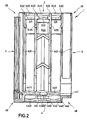
- Interlocking tile 1 has a head part 2, a top fold part 3, a foot fold part 4, a side fold part 5 and a middle field part 6.
- the head side fold corner is 28, the head cover fold corner is 29, the subjectographfalzeck with 48 and the subjectdeckfalzeck with 49.
- the interlocking tile 1 is a hollow interlocking tile which can be laid both in the association and in rows. He has a vertical side and head joint and has a sliding area in the longitudinal direction of the brick, according to bounded below by an uncovered inner head block 215 is. Each in the top deck fold 29 and in the foot side fold corner 48 there is a simple corner cutout.
- an elevation 2142 is attached, which is in the only existing top rabbet groove 214 and in an extension of an elevated midfield 611 extends above.
- the top rebate groove 214 becomes the side rebate 5 by an extension 281 of the inner side rebate rib 513, up through the head edge strip 211, to the right through a lowered extension 292 of the top seam part 3 and after bounded below by the head block 215.
- midfield troughs 612 and 613 are adjacent to an increase in 2142, extending in midfield 611 located, troughs 2141 available.
- the midfield troughs 612 and 613 have at their lowest point, the same as the troughs 211 in the top groove 214 Level to ensure continuous and unobstructed drainage to allow the interlocking of the head on the central tile field. For this purpose are located in the top fold block 215 am lowest point of the troughs drainage openings 2151.
- the increase in 2142 which is in extension of the midfield 611 is not carried out to the top edge strip 211, but has a lowering in front of the head edge strip 2143 on.
- Lowering 2143, troughs 2141 and troughs 612 are preferred and 613 left and right of midfield 611 on the same deep level.
- the top edge strip 211 has in the area of the top hat crimp cutout 29 a hook-shaped bend 291.
- the upper apex surface 312 of the cover fold part 3 is in the area the top rabbet groove 214 lowered.
- the side fold part 5 is with covered side fold ribs 511 and side fold grooves 512 equipped.
- a water switch is located in the bottom seam fold 48 481 and the locking pin 482. In the head side fold corner 28 there is a lowered area 282.
- a locking lug 222 is arranged, the horizontal Stack the tiles on top of each other in the depression 2143 of the top rabbet groove intervenes. It is used to lock the stacked one on top of the other Bricks and prevents the bricks from slipping off each other on the roof.
- the locking lug 222 and the two Hanging tabs 221 form a continuous bar, as it were.
- support ribs 621 which extend up to are carried out to the top edge of the brick and there as stacking bumps 622 act. In the horizontal stacking shown in Figure 3 they lay the brick on the top edge strip 211 of the underlying brick on.
- the hanging lugs 221 and the locking tab 222 preferably have the same height on.
- the foot fold part 4 consists essentially of the inner foot fold rib 441 and the outer foot rib 442.
- the inner False rib 441 has pegs 4411, which change when covering insert the tile into the depressions 2141 of the top groove 214.
- the outer foot rib 442 also has in a manner known per se on pin 4421.
- the supporting ribs 621 have in the area of the roof batten in front of the hanging lugs 221 and the locking lug 222 subsidence 625, in order for the suspension lugs 221 to engage as deeply as possible on the To allow roof batten. This is the case with the invention Roof tiles necessary because the support ribs 621 from the already reasons mentioned were increased.
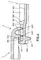
- Figure 4 shows the foot area of a covering brick how it engages in the interlocking head of the covered brick.
- the pins 4411 and 4421 of the foot rebate lie with their lower one End in the trough 2141 of the covered brick.
- Of the Vertical section runs through drainage opening 2151 and shows the type of drainage.
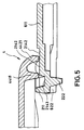
- FIGS. 5 and 6 makes the large headroom with less Coverage clearly.
- Figure 4 in particular shows the large one Displacement range.
- Figure 6 shows the brick III from the side view, however the brick I in vertical section. It can be clearly seen like the water from the water switch 481 into the interlocking head of the covered brick drained.
Landscapes
- Engineering & Computer Science (AREA)
- Architecture (AREA)
- Civil Engineering (AREA)
- Structural Engineering (AREA)
- Chemical & Material Sciences (AREA)
- Ceramic Engineering (AREA)
- Finishing Walls (AREA)
- Roof Covering Using Slabs Or Stiff Sheets (AREA)
- Glass Compositions (AREA)
Description
- Figur 1
- eine Draufsicht auf den erfindungsgemäßen Dachziegel,
- Figur 2
- eine Druntersicht auf den Falzziegel von Figur 1,
- Figur 3
- einen Vertikalschnitt von zwei erfindungsgemäßen Falzziegeln, die horizontal übereinander gestapelt sind,
- Figur 4
- einen Vertikalschnitt gemäß der Linie IV-IV in Figur 1 durch zwei miteinander eingedeckte erfindungsgemäße Ziegeln,
- Figur 5
- einen Vertikalschnitt gemäß der Linie V-V von Figur 1 durch zwei miteinander eingedeckte Ziegel, und
- Figur 6
- einen Teilvertikalschnitt und eine Seitenansicht gemäß der Linie VI-VI von Figur 1 durch zwei miteinanander eingedeckte Ziegel.
Claims (16)
- Falzziegel, vornehmlich Muldenfalzziegel, mit einer Kopf- und Seitenverfalzung und einem Verschiebebereich in Ziegellängsrichtung in Form eines Kopfspielraums, der gegenüber dem Ziegelmittelfeld durch einen quergerichteten, außerhalb der Kopfverfalzung liegenden nicht überdeckten Kopfblock begrenzt ist,
dadurch gekennzeichnet,
daß zwischen dem Kopfblock (215) und dem Kopfrandstreifen (211) eine einzige Kopffalznut (214) vorhanden ist, in die bei Eindeckung gemeinsam die äußere (442) und die innere Fußfalzrippe (441) eingreifen und daß im Bereich der Kopffalznut (214), in Flucht der inneren, nicht überdeckten Seitenfalzrippe (513) eine Verlängerung (281) angebracht und in Flucht des Deckfalzteiles (3) eine abgesenkte Verlängerung (292) des Deckfalzteiles angeordnet ist und beide Verlängerungen mit gleichem Querschnitt bis zum äußeren Kopfrandstreifen (211) durchgehen. - Falzziegel nach Anspruch 1,
dadurch gekennzeichnet,
daß der Kopfrandstreifen (211) in Form einer hakenförmigen Abknickung (291) um den Eckausschnitt (295) im Kopfdeckfalzeck (29) abgewinkelt herumgeführt ist. - Falzziegel nach wenigstens einem der vorhergehenden Ansprüche,
dadurch gekennzeichnet,
daß die innere Fußfalzrippe (441) in gleicher Weise wie die äußere Fußfalzrippe (442) Zapfen (4411, 4421) aufweist. - Falzziegel nach wenigstens einem der vorhergehenden Ansprüche,
dadurch gekennzeichnet,
daß im Bereich des Mittelfeldes (611) auf der Ziegelrückseite in der inneren Fußfalzrippe (441) eine Ausklinkung (4412) angebracht ist, in welche bei der Verdeckung im Verband die hakenförmige Abknickung (291) eingreift. - Falzziegel nach wenigstens einem der vorhergehenden Ansprüche,
dadurch gekennzeichnet,
daß zwischen dem Kopfblock (215) und dem äußeren Kopfrandstreifen (211), also in der vorhandenen einzigen Kopffalznut (214), eine Erhöhung (2142) in Verlängerung des erhöhten Mittelfeldes (611) angebracht ist. - Falzziegel nach wenigstens einem der vorhergehenden Ansprüche,
dadurch gekennzeichnet,
daß die Erhöhung (2142) nicht bis zum äußeren Kopfrandstreifen (211) durchgeführt ist, sondern vor der Einmündung in den äußere Kopfrandstreifen (211) eine Ausnehmung (2143) aufweist. - Falzziegel nach wenigstens einem der vorhergehenden Ansprüche,
dadurch gekennzeichnet,
daß an der Ziegelrückseite zwischen den Aufhängenasen (221) eine Verriegelungsnase (222) angeordnet ist, die beim horizontalen Aufeinanderlegen der Ziegel in die Ausnehmung (2143) eingreift. - Falzziegel nach wenigstens einem der vorhergehenden Ansprüche,
dadurch gekennzeichnet,
daß die Aufhängenasen (221) und die Verriegelungsnase (222) die gleiche Höhe aufweisen. - Falzziegel nach wenigstens einem der vorhergehenden Ansprüche,
dadurch gekennzeichnet,
daß die beiden Aufhängenasen (221) und die Verriegelungsnase (222) zu einer durchgehenden Rippe in Form einer Aufhänge- und Verriegelungsleiste zusammengefaßt sind und ein Teil dieser Leiste beim horizontalen Aufeinanderlegen der Ziegel in die Ausnehmung (2143) eingreift. - Falzziegel nach wenigstens einem der vorhergehenden Ansprüche,
dadurch gekennzeichnet,
daß in Verlängerung der Mulden (612) und (613) links und rechts vom erhöhten Mittelfeld (611), sowie links und rechts von der Erhöhung (2142) in der Kopffalznut (214) ebenfalls Mulden (2141) vorgesehen sind, in welche sowohl die Zapfen (4421) der äußeren Fußfalzrippe (442), als auch die Zapfen (4411) der inneren Fußfalzrippe (441) eingreifen. - Falzziegel nach wenigstens einem der vorhergehenden Ansprüche,
dadurch gekennzeichnet,
daß die in Verlängerung der Mittelfeldmulden (612) und (613) in der Kopffalznut befindlichen Mulden (2141) und die Ausnehmung (2143) in einer Ebene liegen. - Falzziegel nach wenigstens einem der vorhergehenden Ansprüche,
dadurch gekennzeichnet,
daß die an der Ziegelrückseite befindlichen Stützrippen (621) bis zum Kopfrand des Ziegels durchgeführt sind und dort als Stapelhöker (622) wirken, die sich beim horizontalen Aufeinanderlegen der Ziegel auf den Kopfrandstreifen (211) des darunterliegenden Ziegels auflegen. - Falzziegel nach wenigstens einem der vorhergehenden Ansprüche,
dadurch gekennzeichnet,
daß die Stützrippen (621) im Kopfbereich Absenkungen (625) aufweisen. - Falzziegel nach wenigstens einem der vorhergehenden Ansprüche,
dadurch gekennzeichnet,
daß zwischen den Stapelhökern (622) Ausnehmungen (623) angeordnet sind. - Falzziegel nach wenigstens einem der vorhergehenden Ansprüche,
dadurch gekennzeichnet,
daß sich auf der Ziegelrückseite, im Bereich der oberseitigen Erhöhung (2142) eine Ausnehmung (624) befindet. - Falzziegel nach wenigstens einem der vorhergehenden Ansprüche,
dadurch gekennzeichnet,
daß im Anschluß an die Aufhänge- und Verriegelungsleiste Stapelhöker (622) angeordnet sind, die sich beim horizontalen Aufeinanderlegen der Ziegel auf den Kopfrandstreifen (211) des jeweils darunterliegenden Ziegels auflegen.
Applications Claiming Priority (2)
| Application Number | Priority Date | Filing Date | Title |
|---|---|---|---|
| DE9420284U DE9420284U1 (de) | 1994-12-19 | 1994-12-19 | Falzziegel |
| DE9420284U | 1994-12-19 |
Publications (2)
| Publication Number | Publication Date |
|---|---|
| EP0718449A1 EP0718449A1 (de) | 1996-06-26 |
| EP0718449B1 true EP0718449B1 (de) | 1999-08-04 |
Family
ID=6917597
Family Applications (1)
| Application Number | Title | Priority Date | Filing Date |
|---|---|---|---|
| EP95120029A Expired - Lifetime EP0718449B1 (de) | 1994-12-19 | 1995-12-19 | Falzziegel |
Country Status (3)
| Country | Link |
|---|---|
| EP (1) | EP0718449B1 (de) |
| AT (1) | ATE182945T1 (de) |
| DE (2) | DE9420284U1 (de) |
Families Citing this family (4)
| Publication number | Priority date | Publication date | Assignee | Title |
|---|---|---|---|---|
| DE29614609U1 (de) * | 1996-08-22 | 1998-01-02 | Ludowici, Michael Christian, 85540 Haar | Muldenfalzziegel |
| DE19713718C1 (de) * | 1997-04-03 | 1998-10-15 | Rupp Keramik Gmbh | Dachziegel |
| US7690169B2 (en) | 2002-06-19 | 2010-04-06 | Samesor Oy | Roof cladding element and method for manufacturing roof cladding elements |
| DE10300963B4 (de) * | 2003-01-10 | 2016-09-29 | Erlus Aktiengesellschaft | Dachbauelement mit im Querschnitt zunehmender Wasserrille |
Family Cites Families (7)
| Publication number | Priority date | Publication date | Assignee | Title |
|---|---|---|---|---|
| DE1659290A1 (de) * | 1967-12-29 | 1971-01-14 | Berthold Bott Ziegel Gmbh Fa | Dachziegel |
| DE1924185A1 (de) * | 1969-05-12 | 1970-11-19 | Ludowici Michael Christian | Falzziegel |
| DE3708274A1 (de) * | 1987-03-13 | 1988-09-22 | Martin Pehl | Dachfalzziegel |
| DE8711241U1 (de) * | 1987-08-18 | 1987-10-01 | Ludowici, Michael Christian, 8013 Haar | Längsverschiebbare Flachdachpfanne |
| DE8914778U1 (de) * | 1989-12-15 | 1990-02-01 | Ludowici, Michael Christian, 8013 Haar | Längsverschiebbarer Falzziegel |
| DK0440830T3 (da) * | 1990-02-05 | 1993-11-08 | Martin Pehl | Fladtagsten |
| EP0557973B1 (de) * | 1992-02-24 | 1997-01-02 | Michael Christian Ludowici | Längsverschiebbarer Falzziegel |
-
1994
- 1994-12-19 DE DE9420284U patent/DE9420284U1/de not_active Expired - Lifetime
-
1995
- 1995-12-19 EP EP95120029A patent/EP0718449B1/de not_active Expired - Lifetime
- 1995-12-19 AT AT95120029T patent/ATE182945T1/de not_active IP Right Cessation
- 1995-12-19 DE DE59506526T patent/DE59506526D1/de not_active Expired - Lifetime
Also Published As
| Publication number | Publication date |
|---|---|
| ATE182945T1 (de) | 1999-08-15 |
| DE59506526D1 (de) | 1999-09-09 |
| DE9420284U1 (de) | 1996-04-18 |
| EP0718449A1 (de) | 1996-06-26 |
Similar Documents
| Publication | Publication Date | Title |
|---|---|---|
| EP0198479B1 (de) | Flachdachpfanne | |
| EP0432784B1 (de) | Längsverschiebbarer Falzziegel | |
| EP0303993B1 (de) | Längsverschiebbare Flachdachpfanne | |
| EP0432783B1 (de) | Längsverschiebbarer Falzziegel | |
| DE1659290A1 (de) | Dachziegel | |
| EP0718449A1 (de) | Falzziegel | |
| EP0557973B1 (de) | Längsverschiebbarer Falzziegel | |
| CH624171A5 (en) | Longitudinally displaceable interlocking roofing tile | |
| EP0456273B1 (de) | Längsverschiebbarer Falzziegel | |
| EP0585737B1 (de) | Flachdachpfanne | |
| DE4327788C2 (de) | Flachdachpfanne | |
| EP0997588B1 (de) | Biberschwanz-Falzziegel | |
| DE4327789C2 (de) | Flachdachpfanne | |
| DE4327799C2 (de) | Flachdachpfanne | |
| AT408363B (de) | Dachziegel | |
| DE2626595C3 (de) | Falzziegel mit einfacher Kopf- und Fußverfalzung | |
| DE4327802C2 (de) | Flachdachpfanne | |
| DE2738392A1 (de) | Laengsverschiebbares hartbedeckungselement mit einer seiten-, kopf-, fuss- und deckverfalzung | |
| EP0727539B1 (de) | Flachdachpfanne | |
| DE648017C (de) | Hohlstrangfalzziegel | |
| DE19605823B4 (de) | Flachdachpfanne | |
| DE19713718C1 (de) | Dachziegel | |
| DE29820467U1 (de) | Dachziegel | |
| EP0727540B1 (de) | Falzziegel | |
| DE3205929A1 (de) | Laengsverschiebbarer falzziegel |
Legal Events
| Date | Code | Title | Description |
|---|---|---|---|
| PUAI | Public reference made under article 153(3) epc to a published international application that has entered the european phase |
Free format text: ORIGINAL CODE: 0009012 |
|
| AK | Designated contracting states |
Kind code of ref document: A1 Designated state(s): AT CH DE FR GB IT LI NL |
|
| 17P | Request for examination filed |
Effective date: 19960723 |
|
| RBV | Designated contracting states (corrected) |
Designated state(s): AT CH DE FR GB IT LI NL |
|
| GRAG | Despatch of communication of intention to grant |
Free format text: ORIGINAL CODE: EPIDOS AGRA |
|
| 17Q | First examination report despatched |
Effective date: 19980922 |
|
| GRAG | Despatch of communication of intention to grant |
Free format text: ORIGINAL CODE: EPIDOS AGRA |
|
| GRAH | Despatch of communication of intention to grant a patent |
Free format text: ORIGINAL CODE: EPIDOS IGRA |
|
| GRAH | Despatch of communication of intention to grant a patent |
Free format text: ORIGINAL CODE: EPIDOS IGRA |
|
| GRAA | (expected) grant |
Free format text: ORIGINAL CODE: 0009210 |
|
| AK | Designated contracting states |
Kind code of ref document: B1 Designated state(s): AT CH DE FR GB IT LI NL |
|
| REF | Corresponds to: |
Ref document number: 182945 Country of ref document: AT Date of ref document: 19990815 Kind code of ref document: T |
|
| ITF | It: translation for a ep patent filed | ||
| REG | Reference to a national code |
Ref country code: CH Ref legal event code: EP |
|
| GBT | Gb: translation of ep patent filed (gb section 77(6)(a)/1977) |
Effective date: 19990805 |
|
| REF | Corresponds to: |
Ref document number: 59506526 Country of ref document: DE Date of ref document: 19990909 |
|
| REG | Reference to a national code |
Ref country code: CH Ref legal event code: NV Representative=s name: BOVARD AG PATENTANWAELTE |
|
| ET | Fr: translation filed | ||
| PGFP | Annual fee paid to national office [announced via postgrant information from national office to epo] |
Ref country code: GB Payment date: 19991122 Year of fee payment: 5 |
|
| PLBE | No opposition filed within time limit |
Free format text: ORIGINAL CODE: 0009261 |
|
| STAA | Information on the status of an ep patent application or granted ep patent |
Free format text: STATUS: NO OPPOSITION FILED WITHIN TIME LIMIT |
|
| 26N | No opposition filed | ||
| PG25 | Lapsed in a contracting state [announced via postgrant information from national office to epo] |
Ref country code: GB Free format text: LAPSE BECAUSE OF NON-PAYMENT OF DUE FEES Effective date: 20001219 |
|
| PGFP | Annual fee paid to national office [announced via postgrant information from national office to epo] |
Ref country code: FR Payment date: 20001219 Year of fee payment: 6 |
|
| PGFP | Annual fee paid to national office [announced via postgrant information from national office to epo] |
Ref country code: NL Payment date: 20001221 Year of fee payment: 6 |
|
| PGFP | Annual fee paid to national office [announced via postgrant information from national office to epo] |
Ref country code: CH Payment date: 20010108 Year of fee payment: 6 |
|
| GBPC | Gb: european patent ceased through non-payment of renewal fee |
Effective date: 20001219 |
|
| PG25 | Lapsed in a contracting state [announced via postgrant information from national office to epo] |
Ref country code: LI Free format text: LAPSE BECAUSE OF NON-PAYMENT OF DUE FEES Effective date: 20011231 Ref country code: CH Free format text: LAPSE BECAUSE OF NON-PAYMENT OF DUE FEES Effective date: 20011231 |
|
| PG25 | Lapsed in a contracting state [announced via postgrant information from national office to epo] |
Ref country code: NL Free format text: LAPSE BECAUSE OF NON-PAYMENT OF DUE FEES Effective date: 20020701 |
|
| REG | Reference to a national code |
Ref country code: CH Ref legal event code: PL |
|
| PG25 | Lapsed in a contracting state [announced via postgrant information from national office to epo] |
Ref country code: FR Free format text: LAPSE BECAUSE OF NON-PAYMENT OF DUE FEES Effective date: 20020830 |
|
| NLV4 | Nl: lapsed or anulled due to non-payment of the annual fee |
Effective date: 20020701 |
|
| REG | Reference to a national code |
Ref country code: FR Ref legal event code: ST |
|
| PG25 | Lapsed in a contracting state [announced via postgrant information from national office to epo] |
Ref country code: IT Free format text: LAPSE BECAUSE OF NON-PAYMENT OF DUE FEES Effective date: 20051219 |
|
| PGFP | Annual fee paid to national office [announced via postgrant information from national office to epo] |
Ref country code: AT Payment date: 20091222 Year of fee payment: 15 |
|
| PGFP | Annual fee paid to national office [announced via postgrant information from national office to epo] |
Ref country code: DE Payment date: 20110128 Year of fee payment: 16 |
|
| PG25 | Lapsed in a contracting state [announced via postgrant information from national office to epo] |
Ref country code: AT Free format text: LAPSE BECAUSE OF NON-PAYMENT OF DUE FEES Effective date: 20101219 |
|
| REG | Reference to a national code |
Ref country code: DE Ref legal event code: R119 Ref document number: 59506526 Country of ref document: DE Effective date: 20120703 |
|
| PG25 | Lapsed in a contracting state [announced via postgrant information from national office to epo] |
Ref country code: DE Free format text: LAPSE BECAUSE OF NON-PAYMENT OF DUE FEES Effective date: 20120703 |