EP0718462A2 - Elément coupant pour trépan de forage et procédé de montage d'un élément coupant sur un trépan de forage - Google Patents
Elément coupant pour trépan de forage et procédé de montage d'un élément coupant sur un trépan de forage Download PDFInfo
- Publication number
- EP0718462A2 EP0718462A2 EP95119138A EP95119138A EP0718462A2 EP 0718462 A2 EP0718462 A2 EP 0718462A2 EP 95119138 A EP95119138 A EP 95119138A EP 95119138 A EP95119138 A EP 95119138A EP 0718462 A2 EP0718462 A2 EP 0718462A2
- Authority
- EP
- European Patent Office
- Prior art keywords
- cutting element
- cutting
- partial
- cutter
- base
- Prior art date
- Legal status (The legal status is an assumption and is not a legal conclusion. Google has not performed a legal analysis and makes no representation as to the accuracy of the status listed.)
- Granted
Links
- 238000005520 cutting process Methods 0.000 title claims abstract description 221
- 238000000034 method Methods 0.000 title claims description 39
- 238000005219 brazing Methods 0.000 claims description 25
- 230000000295 complement effect Effects 0.000 claims description 8
- 229910052751 metal Inorganic materials 0.000 claims description 7
- 239000002184 metal Substances 0.000 claims description 7
- 238000001816 cooling Methods 0.000 claims description 5
- 239000000758 substrate Substances 0.000 claims description 5
- UONOETXJSWQNOL-UHFFFAOYSA-N tungsten carbide Chemical compound [W+]#[C-] UONOETXJSWQNOL-UHFFFAOYSA-N 0.000 abstract description 6
- 238000005553 drilling Methods 0.000 description 9
- 239000000463 material Substances 0.000 description 8
- 229910003460 diamond Inorganic materials 0.000 description 4
- 239000010432 diamond Substances 0.000 description 4
- 238000010438 heat treatment Methods 0.000 description 3
- 238000010420 art technique Methods 0.000 description 2
- 230000015572 biosynthetic process Effects 0.000 description 2
- 239000011159 matrix material Substances 0.000 description 2
- 150000001875 compounds Chemical class 0.000 description 1
- 230000000694 effects Effects 0.000 description 1
- 238000004519 manufacturing process Methods 0.000 description 1
- 150000002739 metals Chemical class 0.000 description 1
- 238000012986 modification Methods 0.000 description 1
- 230000004048 modification Effects 0.000 description 1
Images


Classifications
-
- E—FIXED CONSTRUCTIONS
- E21—EARTH OR ROCK DRILLING; MINING
- E21B—EARTH OR ROCK DRILLING; OBTAINING OIL, GAS, WATER, SOLUBLE OR MELTABLE MATERIALS OR A SLURRY OF MINERALS FROM WELLS
- E21B10/00—Drill bits
- E21B10/46—Drill bits characterised by wear resisting parts, e.g. diamond inserts
- E21B10/56—Button-type inserts
- E21B10/567—Button-type inserts with preformed cutting elements mounted on a distinct support, e.g. polycrystalline inserts
- E21B10/573—Button-type inserts with preformed cutting elements mounted on a distinct support, e.g. polycrystalline inserts characterised by support details, e.g. the substrate construction or the interface between the substrate and the cutting element
-
- E—FIXED CONSTRUCTIONS
- E21—EARTH OR ROCK DRILLING; MINING
- E21B—EARTH OR ROCK DRILLING; OBTAINING OIL, GAS, WATER, SOLUBLE OR MELTABLE MATERIALS OR A SLURRY OF MINERALS FROM WELLS
- E21B10/00—Drill bits
- E21B10/62—Drill bits characterised by parts, e.g. cutting elements, which are detachable or adjustable
Definitions
- the present invention relates generally to a drill bit cutting element and method for mounting a cutting element on a drill bit and more particularly to such a cutting element and method in which a new or worn cutting element is cut to create at least one partial cutting element.
- a conventional cutting element for an earth boring drill bit typically comprises a substantially cylindrical backing made from a cemented metal carbide such as tungsten carbide.
- One end of the backing has a cutting blank, referred to herein as a cutter, bonded thereto.
- the cutter typically comprises a disk of cemented carbide having a polycrystalline compact diamond (PCD) layer formed on one end thereof which defines a cutting surface.
- the PCD layer may be of the type having metals leached therefrom to enable the cutting element to withstand higher temperatures. In such cases the PCD layer may comprise a mosaic of smaller PCD elements mounted on the end of the substrate.
- Such cutting elements are typically mounted on a drill bit body by brazing.
- the drill bit body is formed with recesses therein for receiving a substantial portion of the cutting element in a manner which presents the PCD layer at an appropriate angle and direction for cutting in accordance with the drill bit design.
- a brazing compound is applied to the surface of the backing and in the recess on the bit body in which the cutting element is received.
- the cutting elements are installed in their respective recesses in the bit body and heat is applied to each cutting element via a torch to raise the temperature to a point which is high enough to braze the cutting elements to the bit body but not so high as to damage the PCD layer.
- the cutting elements are urged against a formation.
- the cutter and portions of the backing adjacent thereto tend to wear away from one side.
- the cutting element is substantially spent and must be removed and replaced or, in some cases, the entire bit must be replaced.
- each half cutting element includes a backing having a substantially flat side surface and a semicircular cross section.
- a half cutter including a PCD layer is mounted on one end of the backing. While half cutting elements are desirable because they provide all the PCD cutting surface normally used during drilling (with less PCD material), the reduced surface area of the semicylindrical backing provides less surface area for brazing the cutting element to the drill bit body. As a result, half cutting elements are relatively easier than a full cutting element to break away from the bit body.
- prior art high temperature brazes exist which provide high strength bonds, the heat required to effect die bond is high enough to damage the PCD cutting layer. Such brazes cannot be used in the process described above in which a torch is used to braze the cutting elements thereto because the cutters will be damaged.
- the present invention comprises a method for mounting a cutting element on an earth boring drill bit.
- the cutting element is of the type having a cutter mounted on a backing.
- the method includes the step of cutting the backing and cutter thereby forming at least one partial cutting element.
- the partial cutting element is mounted on a base to form an integrated unit which is thereafter mounted on a drill bit body.
- a cutting element made in accordance with the method is also provided.
- a pocket is formed on a drill bit body for receiving a partial cutting element which is fitted into the pocket and thereafter brazed to the bit body.
- FIG. 1 is a perspective view of a first embodiment of a cutting element constructed in accordance with the present invention.
- FIG. 2 is a perspective view of a second embodiment of a cutting element.
- FIG. 3 is a perspective view of a third embodiment of a cutting element comprising a partial cutting element and a base and showing a substantially planar boundary between the two.
- FIG. 4 is a sectional view illustrating a portion of another embodiment of the cutting element of FIG. 3 and depicting a slightly different boundary than the planar boundary along line 4-4 in FIG. 3.
- FIG. 5 is a view similar to the view of FIG. 4 illustrating another embodiment of the cutting element of FIG. 3 and depicting a slightly different structure at the boundary.
- FIG. 6 is another embodiment of the cutting element of the present invention illustrating a boundary having complementary geometric features between a partial cutter and a base.
- FIGS. 7-10 are embodiments similar to FIG. 6 showing different complementary geometric features.
- FIG. 11 is an exploded perspective view of a prior art drill bit illustrating the manner in which a cutting element is received in a matrix pocket of the bit.
- FIG. 12 is a cutting element and pocket constructed in accordance with the present invention.
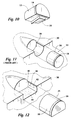
- FIG. 13 is a perspective view of a stud cutter constructed in accordance with the present invention.
- FIG. 14 is a perspective view of another embodiment of a stud cutter constructed in accordance with the present invention.
- FIG. 15 is a perspective view of another embodiment of a stud cutter constructed in accordance with the present invention.
- Cutting element 10 includes a partial cutting element 12 and a base 14.
- Base 14 is preferably formed of tungsten carbide or of a metallic or other bondable material.
- both partial cutting element 12 and base 14 comprise substantially semicylindrical bodies bonded together, in a manner which will hereinafter more fully described, to form a substantially cylindrical unit.
- the present invention can be practiced with other geometries, e.g., a body having triangular or other geometrical cross section such as one half of a hexagon.
- partial cutting element 12 includes a backing 16, which in the present embodiment is formed from a cemented metal carbide such as tungsten carbide.
- a cutter 18 is bonded to one end of backing 16 in a manner which will be more fully described hereinafter.
- Cutter 18 is conventional and may comprise a substrate of cemented carbide having a polycrystalline compact diamond (PCD) formed on one end to define a cutting surface 20.
- Cutter 18 may, e.g., alternately comprise a synthetic diamond mosaic cutter.
- Partial cutting element 12 is obtained by cutting a prior art full cutting element, such as the one indicated generally at 22 in FIG. 11, into two halves generally along a plane containing the longitudinal axis of the cutting element.
- a full cutting element, like cutting element 22 can be cut immediately after it is manufactured to provide two semicylindrical partial cutting elements, like partial cutting element 12, for making two cutting elements, like cutting element 10.
- a prior art full cutting element like cutting element 22 call be installed on a bit as illustrated in FIG. 11 and used until the cutting edge is substantially worn.
- the worn cutting element is then removed from the bit and cut generally along a plane containing the longitudinal axis of the cutting element with the plane being oriented so that substantially all of the worn portion of the full cutting element is on one side of the plane, thereby creating a first partial cutting element which is worn and a second partial cutting element which is substantially unworn, like partial cutting element 12 in FIG. 1.
- partial cutting element 12 is thereafter bonded to semicylindrical base 14.
- the bond so formed is a high strength bond which is heated in a small furnace, such as one that might be used for bonding synthetic diamond to an appropriate substrate as opposed to a furnace capable of receiving an entire matrix bit.
- the furnace is conventional and those skilled in the art can use it, along with a suitable bonding material, to form a high strength bond between the planar surfaces of partial cutting element 12 and base 14. In part, this is accomplished by heating the base and partial cutting element in a manner which would damage cutter 18 except that conventional cooling equipment is used for cooling the cutter during the high strength bonding process.
- the high strength bond is thus formed between partial cutting element 12 and base 14 by heating both bodies to a level which would damage the cutter if the same heat was applied thereto during a conventional brazing process in which each of the cutters are heated with a torch.
- the technique for installing cutting element 10 includes utilizing a conventional brazing material between both backing 16 and base 14 and the surfaces of a pocket, like pocket 28 formed in all earth-boring drill bit body 30 in FIG. 11.
- conventional brazing refers to brazing accomplished with low to moderate temperatures which are not high enough to damage the PDC layer in the cutter. Such conventional brazing can produce bonds in the range of 35,000 to 140,000 p.s.i. shear strength.
- high temperature brazing refers to brazing accomplished with a temperature which is high enough to damage the PDC layer in the cutter in the absence of cooling during brazing. Such high temperature brazing can produce bonds having even higher shear strength than conventional brazing and are known in the art.
- cutting element 10 is oriented to present cutter 18 at an appropriate angle so that a curved edge thereof is presented to an earth formation during drilling.
- each cutting clement is heated , typically with a torch, to produce a low to moderate temperature bond between the cutting elements and the bit body. Because cutting element 10 includes substantially more surface area than a partial cutting element, the low temperature bond is sufficient to retain the cutting element in its pocket during drilling. Although there is a relatively small surface area between base 14 and backing 16, the high temperature bonding process described above produces a high strength bond which maintains its integrity during drilling.
- brazing step required to join cutting element 12 and base 14, in FIG. 1 could be accomplished with a moderate temperature conventional braze and the brazing required to install cutting element 10 into the bit crown pockets could be accomplished with a low temperature conventional braze as described above. It is important that the braze used to join cutting element 12 and base 14 have a higher brazing temperature than that used to install cutting element 10 into a bit crown pocket to prevent debrazing of the bond in cutting element 10 when it is brazed into its associated bit crown pocket.
- FIG. 2 a second cutting element 24 which is constructed in accordance with the present invention is illustrated.
- backing 16 is shorter than cutting element 10.
- Another substantially semicylindrical body portion 26 is received against one end of backing 16 and is likewise abutted against base 14 as shown. Brazing is provided as described above between the surfaces of backing 16 and cutting element 26 which are abutted against base 14 as well as the surfaces of backing 16 and body portion 26 which are directly abutted together.
- Cutting element 24 may be used in substantially the same manner as cutting element 10.
- FIG. 3 indicated generally at 32 is another cutting element constructed in accordance with the present invention.
- neither partial cutting element 12 nor base 14 is substantially semicylindrical.
- Each does, however, include a complimentary substantially planar brazing surface, the boundary of which is shown partially in dashed lines and partially in a solid line, so that when the two are bonded together, a substantially cylindrical unit, as in the cutting elements of FIGS. 1 and 2, is formed.
- FIG. 4 shown therein is an enlarged view of the boundary between a partial cutting element and body, like partial cutting element 12 and body 14 in FIG. 3, in a modified version of the cutter of FIG. 3.
- partial cutting element 12 and body 14 include complementary geometric features which interface with one another to resist shear forces applied to partial cutting element 12 during drilling which tend to break the bond between the partial cutting element and the base.
- FIG. 5 illustrates another modified version of the boundary between the partial cutting element and the base also including complementary geometric features which resist shear forces.
- Such features may be incorporated into an embodiment in which the partial cutting element is not cut from a full cutting element along a cutting plane containing the longitudinal axis of the full cutting element, as in FIG. 3, or may be incorporated into cutting elements like those shown in FIGS.
- FIG. 10 where only a partial cutting element 12 is shown to illustrate an interfacing feature 33 formed thereon.
- a complementary recess is formed in a semicylindrical base (not shown) to engage the feature 33 so as to resist shear forces during drilling.
- full cutting element 22 includes a substantially cylindrical backing 16 and a cutter 18.
- Cutting element 22 may be cut as described above to form partial cutters utilized in the present invention.
- prior art full cutting element 22 is brazed into corresponding pocket 28 formed in bit body 30 utilizing conventional brazing techniques which involve placing a suitable conventional braze and a full cutting element, like full cutting element 22 in each pocket. Thereafter, brazing is accomplished by heating the cutter, the surrounding pocket and the braze with a torch.
- a partial cutter 35 may be received into a pocket, indicated generally at 36, formed on a drill bit body 38. Partial cutter 35 is formed in the same manner as the previously described partial cutters, namely by cutting a full cutting element generally along the length thereof. In the embodiment of FIG. 12, a lower substantially planar surface, not visible, is formed during the cutting process which is substantially parallel to the longitudinal axis of the full cutting element.
- Pocket 36 includes a substantially planar rear surface 40, a curved surface 42 and a substantial planar surface 44 which flushly abuts the cut surface of partial cutter 35 when the same is received in pocket 36.
- a surface (not visible) symmetrical with and opposite to surface 44 comprises a portion of pocket 36.
- a suitable conventional bonding material is placed in pocket 36, on the rear planar surface of backing 16, on the lower planar surface of backing 16 and on the curved lower side surfaces, like surface 42, of the backing.
- bonding material is disposed between substantially all of the abutting surfaces of the pocket and partial cutter 35.
- the cutters surrounding the pockets and braze are heated with a torch to braze the cutters into the pockets.
- the partial cutter and pocket depicted in FIG. 12 provide increased area of contact between the pocket and cutter over prior art techniques for mounting half cutters on bits, and because curved surface 42 and the opposing symmetrical surface tend to retain the partial cutter in the pocket, the bond between the partial cutter and the pocket is able to withstand the forces applied during drilling.
- the cutter of FIG. 10 may be received into a pocket, like pocket 36 in FIG. 12, having a recess complementary to feature 33 formed on surface 44 in order to provide increased mechanical resistance to shear forces.
- FIG. 13 indicated generally at 46 is a stud cutter constructed in accordance with the present invention. Included therein is a cutting element 48 similar to cutting element 10 in FIG. 1.
- the cutting element is mounted on a stud 50, which may be formed from tungsten carbide or may be metallic or other suitable material.
- cutting element 48 is mounted on the stud utilizing high temperature brazing.
- the cutting element may be mounted on the stud using any of the brazing or bonding techniques referred to above or with another suitable technique for securely mounting the cutting element on the stud.
- Stud cutter 46 is mounted, along with other similar stud cutters, on the bit body to create a stud cutter bit.
- FIGS. 14 and 15 illustrate different embodiments of stud cutters in which a half cutter, formed by cutting a new or worn cutter as described above, is brazed to the upper surface of a stud preferably using high temperature brazing.
Landscapes
- Engineering & Computer Science (AREA)
- Geology (AREA)
- Life Sciences & Earth Sciences (AREA)
- Mining & Mineral Resources (AREA)
- Physics & Mathematics (AREA)
- Environmental & Geological Engineering (AREA)
- Fluid Mechanics (AREA)
- Mechanical Engineering (AREA)
- General Life Sciences & Earth Sciences (AREA)
- Geochemistry & Mineralogy (AREA)
- Chemical & Material Sciences (AREA)
- Crystallography & Structural Chemistry (AREA)
- Earth Drilling (AREA)
Applications Claiming Priority (2)
| Application Number | Priority Date | Filing Date | Title |
|---|---|---|---|
| US08/359,187 US5533582A (en) | 1994-12-19 | 1994-12-19 | Drill bit cutting element |
| US359187 | 1994-12-19 |
Publications (3)
| Publication Number | Publication Date |
|---|---|
| EP0718462A2 true EP0718462A2 (fr) | 1996-06-26 |
| EP0718462A3 EP0718462A3 (fr) | 1996-12-27 |
| EP0718462B1 EP0718462B1 (fr) | 2002-04-03 |
Family
ID=23412700
Family Applications (1)
| Application Number | Title | Priority Date | Filing Date |
|---|---|---|---|
| EP95119138A Expired - Lifetime EP0718462B1 (fr) | 1994-12-19 | 1995-12-05 | Elément coupant pour trépan de forage et procédé de montage d'un élément coupant sur un trépan de forage |
Country Status (2)
| Country | Link |
|---|---|
| US (1) | US5533582A (fr) |
| EP (1) | EP0718462B1 (fr) |
Cited By (2)
| Publication number | Priority date | Publication date | Assignee | Title |
|---|---|---|---|---|
| WO2010115617A3 (fr) * | 2009-04-07 | 2011-03-24 | Diamant Drilling Services S.A. | Trepan rotatif |
| US10450808B1 (en) * | 2016-08-26 | 2019-10-22 | Us Synthetic Corporation | Multi-part superabrasive compacts, rotary drill bits including multi-part superabrasive compacts, and related methods |
Families Citing this family (64)
| Publication number | Priority date | Publication date | Assignee | Title |
|---|---|---|---|---|
| GB9621217D0 (en) * | 1996-10-11 | 1996-11-27 | Camco Drilling Group Ltd | Improvements in or relating to preform cutting elements for rotary drill bits |
| GB9803096D0 (en) * | 1998-02-14 | 1998-04-08 | Camco Int Uk Ltd | Improvements in preform elements and mountings therefor |
| US6241036B1 (en) * | 1998-09-16 | 2001-06-05 | Baker Hughes Incorporated | Reinforced abrasive-impregnated cutting elements, drill bits including same |
| DE60320484T2 (de) * | 2002-06-07 | 2009-05-14 | Black & Decker Inc., Newark | Kraftgetriebenes Werkzeug mit Blockiereinrichtung |
| DE10236483A1 (de) | 2002-08-08 | 2004-02-19 | Hilti Ag | Hartstoffeinsatz mit polykristalliner Diamantschicht |
| US7234550B2 (en) * | 2003-02-12 | 2007-06-26 | Smith International, Inc. | Bits and cutting structures |
| US20060032677A1 (en) * | 2003-02-12 | 2006-02-16 | Smith International, Inc. | Novel bits and cutting structures |
| US7040424B2 (en) * | 2003-03-04 | 2006-05-09 | Smith International, Inc. | Drill bit and cutter having insert clusters and method of manufacture |
| US7461709B2 (en) * | 2003-08-21 | 2008-12-09 | Smith International, Inc. | Multiple diameter cutting elements and bits incorporating the same |
| US7395882B2 (en) | 2004-02-19 | 2008-07-08 | Baker Hughes Incorporated | Casing and liner drilling bits |
| US7624818B2 (en) * | 2004-02-19 | 2009-12-01 | Baker Hughes Incorporated | Earth boring drill bits with casing component drill out capability and methods of use |
| US7954570B2 (en) * | 2004-02-19 | 2011-06-07 | Baker Hughes Incorporated | Cutting elements configured for casing component drillout and earth boring drill bits including same |
| US7757789B2 (en) * | 2005-06-21 | 2010-07-20 | Smith International, Inc. | Drill bit and insert having bladed interface between substrate and coating |
| US7757793B2 (en) * | 2005-11-01 | 2010-07-20 | Smith International, Inc. | Thermally stable polycrystalline ultra-hard constructions |
| US7621351B2 (en) * | 2006-05-15 | 2009-11-24 | Baker Hughes Incorporated | Reaming tool suitable for running on casing or liner |
| US8714285B2 (en) | 2006-08-11 | 2014-05-06 | Schlumberger Technology Corporation | Method for drilling with a fixed bladed bit |
| US8215420B2 (en) | 2006-08-11 | 2012-07-10 | Schlumberger Technology Corporation | Thermally stable pointed diamond with increased impact resistance |
| US8622155B2 (en) | 2006-08-11 | 2014-01-07 | Schlumberger Technology Corporation | Pointed diamond working ends on a shear bit |
| US8590644B2 (en) | 2006-08-11 | 2013-11-26 | Schlumberger Technology Corporation | Downhole drill bit |
| US9051795B2 (en) | 2006-08-11 | 2015-06-09 | Schlumberger Technology Corporation | Downhole drill bit |
| US7637574B2 (en) | 2006-08-11 | 2009-12-29 | Hall David R | Pick assembly |
| US8567532B2 (en) | 2006-08-11 | 2013-10-29 | Schlumberger Technology Corporation | Cutting element attached to downhole fixed bladed bit at a positive rake angle |
| US9145742B2 (en) | 2006-08-11 | 2015-09-29 | Schlumberger Technology Corporation | Pointed working ends on a drill bit |
| US7669674B2 (en) | 2006-08-11 | 2010-03-02 | Hall David R | Degradation assembly |
| US8960337B2 (en) | 2006-10-26 | 2015-02-24 | Schlumberger Technology Corporation | High impact resistant tool with an apex width between a first and second transitions |
| US9068410B2 (en) | 2006-10-26 | 2015-06-30 | Schlumberger Technology Corporation | Dense diamond body |
| US7798258B2 (en) * | 2007-01-03 | 2010-09-21 | Smith International, Inc. | Drill bit with cutter element having crossing chisel crests |
| US7686106B2 (en) * | 2007-01-03 | 2010-03-30 | Smith International, Inc. | Rock bit and inserts with wear relief grooves |
| US8205692B2 (en) * | 2007-01-03 | 2012-06-26 | Smith International, Inc. | Rock bit and inserts with a chisel crest having a broadened region |
| US7631709B2 (en) | 2007-01-03 | 2009-12-15 | Smith International, Inc. | Drill bit and cutter element having chisel crest with protruding pilot portion |
| EP3081738A1 (fr) | 2007-01-31 | 2016-10-19 | Halliburton Energy Services, Inc. | Trépans de forage rotatifs avec éléments tranchants protégés et leurs procédés |
| USD554162S1 (en) * | 2007-03-27 | 2007-10-30 | Hall David R | Diamond enhanced cutting element |
| US8074869B2 (en) * | 2007-09-24 | 2011-12-13 | Baker Hughes Incorporated | System, method, and apparatus for reactive foil brazing of cutter components for fixed cutter bit |
| US7954571B2 (en) * | 2007-10-02 | 2011-06-07 | Baker Hughes Incorporated | Cutting structures for casing component drillout and earth-boring drill bits including same |
| US8245797B2 (en) * | 2007-10-02 | 2012-08-21 | Baker Hughes Incorporated | Cutting structures for casing component drillout and earth-boring drill bits including same |
| US9217296B2 (en) | 2008-01-09 | 2015-12-22 | Smith International, Inc. | Polycrystalline ultra-hard constructions with multiple support members |
| US7909121B2 (en) * | 2008-01-09 | 2011-03-22 | Smith International, Inc. | Polycrystalline ultra-hard compact constructions |
| US8540037B2 (en) | 2008-04-30 | 2013-09-24 | Schlumberger Technology Corporation | Layered polycrystalline diamond |
| GB2479844B (en) * | 2009-01-29 | 2013-06-19 | Smith International | Brazing methods for PDC cutters |
| US8701799B2 (en) | 2009-04-29 | 2014-04-22 | Schlumberger Technology Corporation | Drill bit cutter pocket restitution |
| US10005672B2 (en) | 2010-04-14 | 2018-06-26 | Baker Hughes, A Ge Company, Llc | Method of forming particles comprising carbon and articles therefrom |
| SA111320374B1 (ar) | 2010-04-14 | 2015-08-10 | بيكر هوغيس انكوبوريتد | طريقة تشكيل الماسة متعدد البلورات من الماس المستخرج بحجم النانو |
| US9205531B2 (en) | 2011-09-16 | 2015-12-08 | Baker Hughes Incorporated | Methods of fabricating polycrystalline diamond, and cutting elements and earth-boring tools comprising polycrystalline diamond |
| EP2561171B1 (fr) | 2010-04-23 | 2018-01-10 | Baker Hughes, a GE company, LLC | Eléments de coupe destinés à des outils de forage, outils de forage incluant lesdits éléments de coupe et procédés connexes |
| US8985248B2 (en) | 2010-08-13 | 2015-03-24 | Baker Hughes Incorporated | Cutting elements including nanoparticles in at least one portion thereof, earth-boring tools including such cutting elements, and related methods |
| US20120192680A1 (en) * | 2011-01-27 | 2012-08-02 | Baker Hughes Incorporated | Fabricated Mill Body with Blade Pockets for Insert Placement and Alignment |
| US8607899B2 (en) | 2011-02-18 | 2013-12-17 | National Oilwell Varco, L.P. | Rock bit and cutter teeth geometries |
| US8991525B2 (en) | 2012-05-01 | 2015-03-31 | Baker Hughes Incorporated | Earth-boring tools having cutting elements with cutting faces exhibiting multiple coefficients of friction, and related methods |
| US9650837B2 (en) | 2011-04-22 | 2017-05-16 | Baker Hughes Incorporated | Multi-chamfer cutting elements having a shaped cutting face and earth-boring tools including such cutting elements |
| US9243452B2 (en) | 2011-04-22 | 2016-01-26 | Baker Hughes Incorporated | Cutting elements for earth-boring tools, earth-boring tools including such cutting elements, and related methods |
| US9482057B2 (en) | 2011-09-16 | 2016-11-01 | Baker Hughes Incorporated | Cutting elements for earth-boring tools, earth-boring tools including such cutting elements and related methods |
| US9428966B2 (en) | 2012-05-01 | 2016-08-30 | Baker Hughes Incorporated | Cutting elements for earth-boring tools, earth-boring tools including such cutting elements, and related methods |
| US9103174B2 (en) | 2011-04-22 | 2015-08-11 | Baker Hughes Incorporated | Cutting elements for earth-boring tools, earth-boring tools including such cutting elements and related methods |
| RU2014114867A (ru) | 2011-09-16 | 2015-10-27 | Бейкер Хьюз Инкорпорейтед | Способы изготовления поликристаллического алмаза, а также режущих элементов и буровых инструментов, содержащих поликристаллический алмаз |
| US9194189B2 (en) | 2011-09-19 | 2015-11-24 | Baker Hughes Incorporated | Methods of forming a cutting element for an earth-boring tool, a related cutting element, and an earth-boring tool including such a cutting element |
| US9303460B2 (en) * | 2012-02-03 | 2016-04-05 | Baker Hughes Incorporated | Cutting element retention for high exposure cutting elements on earth-boring tools |
| WO2014105454A1 (fr) | 2012-12-26 | 2014-07-03 | Smith International, Inc. | Molette dotée d'un support inférieur |
| US20140183798A1 (en) | 2012-12-28 | 2014-07-03 | Smith International, Inc. | Manufacture of cutting elements having lobes |
| US9140072B2 (en) | 2013-02-28 | 2015-09-22 | Baker Hughes Incorporated | Cutting elements including non-planar interfaces, earth-boring tools including such cutting elements, and methods of forming cutting elements |
| CN108474239A (zh) | 2016-01-13 | 2018-08-31 | 斯伦贝谢技术有限公司 | 成角度的凿子插入件 |
| WO2021091834A1 (fr) * | 2019-11-06 | 2021-05-14 | National Oilwell DHT, L.P. | Fixation mécanique d'éléments de coupe à un trépan de forage |
| CN113107374B (zh) * | 2021-05-12 | 2024-12-27 | 西安石油大学 | 一种仿生pdc-孕镶耦合仿生钻头主切削结构 |
| USD1026981S1 (en) * | 2021-10-14 | 2024-05-14 | Sf Diamond Co., Ltd. | Polycrystalline diamond compact with a tripartite raised surface |
| USD1026980S1 (en) | 2021-10-14 | 2024-05-14 | Sf Diamond Co., Ltd. | Polycrystalline diamond compact with a raised surface and groove therein |
Family Cites Families (14)
| Publication number | Priority date | Publication date | Assignee | Title |
|---|---|---|---|---|
| DE2719330C3 (de) * | 1977-04-30 | 1984-01-05 | Christensen, Inc., 84115 Salt Lake City, Utah | Drehbohrmeißel |
| US4244432A (en) * | 1978-06-08 | 1981-01-13 | Christensen, Inc. | Earth-boring drill bits |
| US4221270A (en) * | 1978-12-18 | 1980-09-09 | Smith International, Inc. | Drag bit |
| US4373593A (en) * | 1979-03-16 | 1983-02-15 | Christensen, Inc. | Drill bit |
| US4373410A (en) * | 1980-07-21 | 1983-02-15 | Kenneth Davis | Method and apparatus for fabricating diamond stud assemblies |
| DE3111156C1 (de) * | 1981-03-21 | 1983-04-14 | Christensen, Inc., 84115 Salt Lake City, Utah | Schneidglied fuer Drehbohrmeissel zum Tiefbohren in Erdformationen |
| GB8500925D0 (en) * | 1985-01-15 | 1985-02-20 | Nl Petroleum Prod | Cutter assemblies |
| US4606418A (en) * | 1985-07-26 | 1986-08-19 | Reed Tool Company | Cutting means for drag drill bits |
| US4767050A (en) * | 1986-03-24 | 1988-08-30 | General Electric Company | Pocketed stud for polycrystalline diamond cutting blanks and method of making same |
| US4877096A (en) * | 1987-11-17 | 1989-10-31 | Eastman Christensen Company | Replaceable cutter using internal ductile metal receptacles |
| DE68916572T2 (de) * | 1988-04-05 | 1995-01-12 | Camco Drilling Group Ltd | Schneidelement für Drehbohrmeissel und dessen Herstellung. |
| US5011515B1 (en) * | 1989-08-07 | 1999-07-06 | Robert H Frushour | Composite polycrystalline diamond compact with improved impact resistance |
| US5348109A (en) * | 1992-10-07 | 1994-09-20 | Camco Drilling Group Ltd. | Cutter assemblies and cutting elements for rotary drill bits |
| US5373908A (en) * | 1993-03-10 | 1994-12-20 | Baker Hughes Incorporated | Chamfered cutting structure for downhole drilling |
-
1994
- 1994-12-19 US US08/359,187 patent/US5533582A/en not_active Expired - Fee Related
-
1995
- 1995-12-05 EP EP95119138A patent/EP0718462B1/fr not_active Expired - Lifetime
Non-Patent Citations (1)
| Title |
|---|
| None |
Cited By (5)
| Publication number | Priority date | Publication date | Assignee | Title |
|---|---|---|---|---|
| WO2010115617A3 (fr) * | 2009-04-07 | 2011-03-24 | Diamant Drilling Services S.A. | Trepan rotatif |
| BE1019607A3 (fr) * | 2009-04-07 | 2012-09-04 | Diamant Drilling Services S A | Trepan rotatif. |
| US10450808B1 (en) * | 2016-08-26 | 2019-10-22 | Us Synthetic Corporation | Multi-part superabrasive compacts, rotary drill bits including multi-part superabrasive compacts, and related methods |
| US11180961B1 (en) * | 2016-08-26 | 2021-11-23 | Us Synthetic Corporation | Multi-part superabrasive compacts, rotary drill bits including multi-part superabrasive compacts, and related methods |
| US11649682B1 (en) * | 2016-08-26 | 2023-05-16 | Us Synthetic Corporation | Multi-part superabrasive compacts, rotary drill bits including multi-part superabrasive compacts, and related methods |
Also Published As
| Publication number | Publication date |
|---|---|
| EP0718462A3 (fr) | 1996-12-27 |
| US5533582A (en) | 1996-07-09 |
| EP0718462B1 (fr) | 2002-04-03 |
Similar Documents
| Publication | Publication Date | Title |
|---|---|---|
| US5533582A (en) | Drill bit cutting element | |
| US4529048A (en) | Inserts having two components anchored together at a non-perpendicular angle of attachment for use in rotary type drag bits | |
| US4359112A (en) | Hybrid diamond insert platform locator and retention method | |
| US6248447B1 (en) | Cutting elements and methods of manufacture thereof | |
| US7159487B2 (en) | Method for making a polycrystalline diamond insert drill bit body | |
| EP0246789A2 (fr) | Elément de coupe pour un trépan rotatif, trépan rotatif avec un tel élément, et procédé de fabrication de cet élément | |
| EP0145421B1 (fr) | Fabrication de trépans de forage rotatifs | |
| EP0733776B1 (fr) | Trépan racleur avec inserts de calibre en diamant polycristallin | |
| US10400516B2 (en) | Drill bits and methods for manufacturing the same | |
| CA2373415C (fr) | Alesoir et meche-alesoir | |
| EP0144222A2 (fr) | Trépan de forage rotatif | |
| US5060739A (en) | Cutter assemblies for rotary drill bits, and method of manufacturing same | |
| EP0104893A2 (fr) | Composant d'outil | |
| EP0381793B1 (fr) | Méthode pour fabriquer un élément de coupe diamanté avec arête de coupe en V | |
| EP0291314A2 (fr) | Structure de coupe et trépan de forage rotatif comportant une telle structure | |
| EP0880419B1 (fr) | Outil d'usinage et son procede de fabrication | |
| US4711144A (en) | Drill bit and method of manufacture | |
| US4898252A (en) | Cutting structures for rotary drill bits | |
| EP0151031A2 (fr) | Procédé de fabrication de forets | |
| EP0608112A1 (fr) | Organes de coupe pour trépans | |
| EP0534370B1 (fr) | Trépan racleur diamanté | |
| US4570725A (en) | Drill bit cutter | |
| US8336648B1 (en) | Mechanical attachment of thermally stable diamond to a substrate | |
| GB2084219A (en) | Mounting of cutters on cutting tools | |
| EP0383508A2 (fr) | Améliorations aux méthodes ou améliorations relatives aux méthodes de fabrication d'organes de coupe pour trépans |
Legal Events
| Date | Code | Title | Description |
|---|---|---|---|
| PUAI | Public reference made under article 153(3) epc to a published international application that has entered the european phase |
Free format text: ORIGINAL CODE: 0009012 |
|
| AK | Designated contracting states |
Kind code of ref document: A2 Designated state(s): BE GB IE SE |
|
| PUAL | Search report despatched |
Free format text: ORIGINAL CODE: 0009013 |
|
| AK | Designated contracting states |
Kind code of ref document: A3 Designated state(s): BE GB IE SE |
|
| 17P | Request for examination filed |
Effective date: 19970210 |
|
| 17Q | First examination report despatched |
Effective date: 19991125 |
|
| GRAG | Despatch of communication of intention to grant |
Free format text: ORIGINAL CODE: EPIDOS AGRA |
|
| GRAG | Despatch of communication of intention to grant |
Free format text: ORIGINAL CODE: EPIDOS AGRA |
|
| GRAG | Despatch of communication of intention to grant |
Free format text: ORIGINAL CODE: EPIDOS AGRA |
|
| GRAH | Despatch of communication of intention to grant a patent |
Free format text: ORIGINAL CODE: EPIDOS IGRA |
|
| GRAH | Despatch of communication of intention to grant a patent |
Free format text: ORIGINAL CODE: EPIDOS IGRA |
|
| REG | Reference to a national code |
Ref country code: GB Ref legal event code: IF02 |
|
| GRAA | (expected) grant |
Free format text: ORIGINAL CODE: 0009210 |
|
| AK | Designated contracting states |
Kind code of ref document: B1 Designated state(s): BE GB IE SE |
|
| REG | Reference to a national code |
Ref country code: IE Ref legal event code: FG4D |
|
| PG25 | Lapsed in a contracting state [announced via postgrant information from national office to epo] |
Ref country code: SE Free format text: LAPSE BECAUSE OF FAILURE TO SUBMIT A TRANSLATION OF THE DESCRIPTION OR TO PAY THE FEE WITHIN THE PRESCRIBED TIME-LIMIT Effective date: 20020703 |
|
| PGFP | Annual fee paid to national office [announced via postgrant information from national office to epo] |
Ref country code: GB Payment date: 20021127 Year of fee payment: 8 |
|
| PGFP | Annual fee paid to national office [announced via postgrant information from national office to epo] |
Ref country code: IE Payment date: 20021204 Year of fee payment: 8 |
|
| PGFP | Annual fee paid to national office [announced via postgrant information from national office to epo] |
Ref country code: BE Payment date: 20021218 Year of fee payment: 8 |
|
| PLBE | No opposition filed within time limit |
Free format text: ORIGINAL CODE: 0009261 |
|
| STAA | Information on the status of an ep patent application or granted ep patent |
Free format text: STATUS: NO OPPOSITION FILED WITHIN TIME LIMIT |
|
| 26N | No opposition filed |
Effective date: 20030106 |
|
| PG25 | Lapsed in a contracting state [announced via postgrant information from national office to epo] |
Ref country code: IE Free format text: LAPSE BECAUSE OF NON-PAYMENT OF DUE FEES Effective date: 20031205 Ref country code: GB Free format text: LAPSE BECAUSE OF NON-PAYMENT OF DUE FEES Effective date: 20031205 |
|
| PG25 | Lapsed in a contracting state [announced via postgrant information from national office to epo] |
Ref country code: BE Free format text: LAPSE BECAUSE OF NON-PAYMENT OF DUE FEES Effective date: 20031231 |
|
| BERE | Be: lapsed |
Owner name: *BAKER HUGHES INC. Effective date: 20031231 |
|
| GBPC | Gb: european patent ceased through non-payment of renewal fee |
Effective date: 20031205 |
|
| REG | Reference to a national code |
Ref country code: IE Ref legal event code: MM4A |