EP0718518A1 - Accouplement - Google Patents
Accouplement Download PDFInfo
- Publication number
- EP0718518A1 EP0718518A1 EP95119109A EP95119109A EP0718518A1 EP 0718518 A1 EP0718518 A1 EP 0718518A1 EP 95119109 A EP95119109 A EP 95119109A EP 95119109 A EP95119109 A EP 95119109A EP 0718518 A1 EP0718518 A1 EP 0718518A1
- Authority
- EP
- European Patent Office
- Prior art keywords
- cylinder
- diameter
- coupling according
- piston
- cylindrical body
- Prior art date
- Legal status (The legal status is an assumption and is not a legal conclusion. Google has not performed a legal analysis and makes no representation as to the accuracy of the status listed.)
- Granted
Links
Images
Classifications
-
- F—MECHANICAL ENGINEERING; LIGHTING; HEATING; WEAPONS; BLASTING
- F16—ENGINEERING ELEMENTS AND UNITS; GENERAL MEASURES FOR PRODUCING AND MAINTAINING EFFECTIVE FUNCTIONING OF MACHINES OR INSTALLATIONS; THERMAL INSULATION IN GENERAL
- F16D—COUPLINGS FOR TRANSMITTING ROTATION; CLUTCHES; BRAKES
- F16D3/00—Yielding couplings, i.e. with means permitting movement between the connected parts during the drive
- F16D3/50—Yielding couplings, i.e. with means permitting movement between the connected parts during the drive with the coupling parts connected by one or more intermediate members
- F16D3/64—Yielding couplings, i.e. with means permitting movement between the connected parts during the drive with the coupling parts connected by one or more intermediate members comprising elastic elements arranged between substantially-radial walls of both coupling parts
- F16D3/68—Yielding couplings, i.e. with means permitting movement between the connected parts during the drive with the coupling parts connected by one or more intermediate members comprising elastic elements arranged between substantially-radial walls of both coupling parts the elements being made of rubber or similar material
-
- F—MECHANICAL ENGINEERING; LIGHTING; HEATING; WEAPONS; BLASTING
- F16—ENGINEERING ELEMENTS AND UNITS; GENERAL MEASURES FOR PRODUCING AND MAINTAINING EFFECTIVE FUNCTIONING OF MACHINES OR INSTALLATIONS; THERMAL INSULATION IN GENERAL
- F16D—COUPLINGS FOR TRANSMITTING ROTATION; CLUTCHES; BRAKES
- F16D13/00—Friction clutches
- F16D13/58—Details
- F16D13/60—Clutching elements
- F16D13/64—Clutch-plates; Clutch-lamellae
- F16D13/68—Attachments of plates or lamellae to their supports
- F16D13/686—Attachments of plates or lamellae to their supports with one or more intermediate members made of rubber or like material transmitting torque from the linings to the hub
-
- F—MECHANICAL ENGINEERING; LIGHTING; HEATING; WEAPONS; BLASTING
- F16—ENGINEERING ELEMENTS AND UNITS; GENERAL MEASURES FOR PRODUCING AND MAINTAINING EFFECTIVE FUNCTIONING OF MACHINES OR INSTALLATIONS; THERMAL INSULATION IN GENERAL
- F16F—SPRINGS; SHOCK-ABSORBERS; MEANS FOR DAMPING VIBRATION
- F16F1/00—Springs
- F16F1/36—Springs made of rubber or other material having high internal friction, e.g. thermoplastic elastomers
- F16F1/42—Springs made of rubber or other material having high internal friction, e.g. thermoplastic elastomers characterised by the mode of stressing
- F16F1/44—Springs made of rubber or other material having high internal friction, e.g. thermoplastic elastomers characterised by the mode of stressing loaded mainly in compression
- F16F1/445—Springs made of rubber or other material having high internal friction, e.g. thermoplastic elastomers characterised by the mode of stressing loaded mainly in compression the spring material being contained in a generally closed space
-
- F—MECHANICAL ENGINEERING; LIGHTING; HEATING; WEAPONS; BLASTING
- F16—ENGINEERING ELEMENTS AND UNITS; GENERAL MEASURES FOR PRODUCING AND MAINTAINING EFFECTIVE FUNCTIONING OF MACHINES OR INSTALLATIONS; THERMAL INSULATION IN GENERAL
- F16F—SPRINGS; SHOCK-ABSORBERS; MEANS FOR DAMPING VIBRATION
- F16F15/00—Suppression of vibrations in systems; Means or arrangements for avoiding or reducing out-of-balance forces, e.g. due to motion
- F16F15/10—Suppression of vibrations in rotating systems by making use of members moving with the system
- F16F15/12—Suppression of vibrations in rotating systems by making use of members moving with the system using elastic members or friction-damping members, e.g. between a rotating shaft and a gyratory mass mounted thereon
- F16F15/121—Suppression of vibrations in rotating systems by making use of members moving with the system using elastic members or friction-damping members, e.g. between a rotating shaft and a gyratory mass mounted thereon using springs as elastic members, e.g. metallic springs
- F16F15/127—Suppression of vibrations in rotating systems by making use of members moving with the system using elastic members or friction-damping members, e.g. between a rotating shaft and a gyratory mass mounted thereon using springs as elastic members, e.g. metallic springs using plastics springs combined with other types of springs
-
- F—MECHANICAL ENGINEERING; LIGHTING; HEATING; WEAPONS; BLASTING
- F16—ENGINEERING ELEMENTS AND UNITS; GENERAL MEASURES FOR PRODUCING AND MAINTAINING EFFECTIVE FUNCTIONING OF MACHINES OR INSTALLATIONS; THERMAL INSULATION IN GENERAL
- F16F—SPRINGS; SHOCK-ABSORBERS; MEANS FOR DAMPING VIBRATION
- F16F2236/00—Mode of stressing of basic spring or damper elements or devices incorporating such elements
- F16F2236/04—Compression
- F16F2236/045—Compression the spring material being generally enclosed
Definitions
- the invention relates to a clutch according to the preamble of claim 1.
- a clutch of a motor vehicle has the further task of reducing the torsional vibrations in the drive train caused by the irregularity of the engine running.
- Such torsional vibrations can create strength problems, develop undesirable noises from gear rattling, load change vibrations or body groaning and impair driving comfort.
- the invention has for its object to avoid the known blows with the simplest possible means.
- the clamping bodies according to the invention use the cylindrical body as a hydraulic fluid which, when axially deformed, presses fully against the inner wall of the cylinder.
- the load can be increased by about ten times the possible load with spring bodies. An initially almost linear and then a strongly progressive suspension is achieved, which leads to the non-positive coupling of the Leading disc with the drive plate.
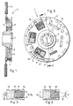
- FIGS. 1 and 2 show the secondary part 1 of a clutch according to the invention, consisting essentially of a drive plate 2, which has on its outer circumference friction linings 3, on which the coupling flanges of a two-part primary part, not shown, are capable of engaging in pliers-like fashion on both sides.
- the drive plate 2 is firmly connected to a flange 5 by means of rivets or screws. Between this flange 5 and the drive plate 2, a drag plate 6 is fastened on an output shaft 7, for this purpose relatively rotatable.
- the recesses 13 in the driving plate 2 and in the flange 5 extend in the circumferential direction over a wider angular range than the recesses 8 in the drag plate 6.
- spring bodies 9 can be designed in a known manner as spring elements in the form of torsion compression springs 12, which are inserted in the cage-like recess 8 of the drag plate 6 and protrude into the recesses 13 of the driving plate 2.
- All or part of the spring bodies 9 can, however, also be designed as tensioning bodies 14 according to the invention, as shown in FIGS. 3 and 4 in a relieved or loaded state.
- Each clamping body 14 consists of a cylinder 15 and a piston 16.
- the cylinder space 17 is provided with a body 18 which is cylindrical in the rest state and made of an elastoplastic material, e.g. Rubber, filled.
- the bore of the cylinder 15 is tapered towards its bottom and has a diameter d2 there that is equal to that d of the cylindrical body 18.
- the piston 16 has a conical depression 19 with an opening angle ⁇ of approximately 20 °, the basic diameter d 1 of which is equal to that d of the cylindrical body 18.
- the piston 16 is advantageously made of a material whose modulus of elasticity is smaller than that of the cylinder 15, e.g. made of plastic.
- the lip of the piston 16 formed by the depression 19 is pressed firmly against the inner wall of the cylinder 15 and serves as a seal there.
- the cylindrical body 15 acts like a hydraulic fluid and, as shown in FIG. 4, deforms in a barrel shape. In this way, very large forces can be transferred.
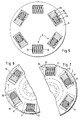
- FIG. 5 shows a drag disc 6 of a clutch with spring bodies 9 which are designed alternately as a torsion spring 12 and tensioning body 14.
- a modified characteristic curve can thereby be achieved.
- the characteristic curve also depends on the diameters d and D of the cylindrical body 18 and the cylinder 15 of the clamping body 14.
- FIGS. 6 and 7 show a coupling according to the invention in each case under tensile and shear loads.
- the rear edge 10 of each recess 13 of the drive plate 2 engages at the rear end of the piston 16 or the torsion spring 12 and compresses the cylindrical body 18 until it ends the relative movement of the piston 16 and cylinder 15.
- the coupling according to the invention is particularly suitable for torsional vibration dampers, damped friction disks in couplings and couplings for connecting two shafts in the case of an elastic coupling.
Landscapes
- Engineering & Computer Science (AREA)
- General Engineering & Computer Science (AREA)
- Mechanical Engineering (AREA)
- Health & Medical Sciences (AREA)
- Child & Adolescent Psychology (AREA)
- Physics & Mathematics (AREA)
- Acoustics & Sound (AREA)
- Aviation & Aerospace Engineering (AREA)
- Mechanical Operated Clutches (AREA)
- Hydraulic Clutches, Magnetic Clutches, Fluid Clutches, And Fluid Joints (AREA)
Applications Claiming Priority (2)
| Application Number | Priority Date | Filing Date | Title |
|---|---|---|---|
| DE4445257A DE4445257C2 (de) | 1994-12-19 | 1994-12-19 | Kupplung |
| DE4445257 | 1994-12-19 |
Publications (2)
| Publication Number | Publication Date |
|---|---|
| EP0718518A1 true EP0718518A1 (fr) | 1996-06-26 |
| EP0718518B1 EP0718518B1 (fr) | 1998-02-04 |
Family
ID=6536245
Family Applications (1)
| Application Number | Title | Priority Date | Filing Date |
|---|---|---|---|
| EP95119109A Expired - Lifetime EP0718518B1 (fr) | 1994-12-19 | 1995-12-05 | Accouplement |
Country Status (5)
| Country | Link |
|---|---|
| US (1) | US5687827A (fr) |
| EP (1) | EP0718518B1 (fr) |
| JP (1) | JPH08219172A (fr) |
| DE (1) | DE4445257C2 (fr) |
| ES (1) | ES2115310T3 (fr) |
Cited By (1)
| Publication number | Priority date | Publication date | Assignee | Title |
|---|---|---|---|---|
| EP0922878A2 (fr) | 1997-10-29 | 1999-06-16 | Rohs-Voigt Patentverwertungsgesellschaft mbH | Amortisseur de vibrations torsionelles |
Families Citing this family (1)
| Publication number | Priority date | Publication date | Assignee | Title |
|---|---|---|---|---|
| US20070230838A1 (en) * | 2006-03-28 | 2007-10-04 | Steven Fulton | Compliant rail linear guide |
Citations (4)
| Publication number | Priority date | Publication date | Assignee | Title |
|---|---|---|---|---|
| GB303656A (en) * | 1928-01-14 | 1929-01-10 | Thomas Carlyle Ellison Rowland | Improvements in or relating to universal joints for the transmission of power |
| US2964930A (en) | 1957-10-28 | 1960-12-20 | Aira | Clutch cushion device |
| US4156481A (en) | 1976-06-03 | 1979-05-29 | Aisin Seiki Kabushiki Kaisha | Friction clutch for automotive vehicles |
| CH645959A5 (en) * | 1980-04-03 | 1984-10-31 | Schweizerische Lokomotiv | Spring element for vehicle drives |
Family Cites Families (8)
| Publication number | Priority date | Publication date | Assignee | Title |
|---|---|---|---|---|
| US2513379A (en) * | 1944-09-28 | 1950-07-04 | Dana Corp | Friction clutch plate |
| GB715512A (en) * | 1952-05-12 | 1954-09-15 | Laycock Eng Ltd | Improvements in or relating to torque dampers |
| US3386265A (en) * | 1966-09-27 | 1968-06-04 | Lord Corp | Torsionally resilient drive |
| US3504901A (en) * | 1969-02-10 | 1970-04-07 | Goodyear Tire & Rubber | Shock absorber |
| JPS5042935Y2 (fr) * | 1971-06-29 | 1975-12-08 | ||
| FR2521244B1 (fr) * | 1982-02-09 | 1986-08-29 | Valeo | |
| FR2541403B1 (fr) * | 1983-02-21 | 1986-06-20 | Valeo | Dispositif amortisseur de torsion, en particulier friction d'embrayage, notamment pour vehicule automobile |
| JPH03114632U (fr) * | 1990-03-07 | 1991-11-26 |
-
1994
- 1994-12-19 DE DE4445257A patent/DE4445257C2/de not_active Expired - Fee Related
-
1995
- 1995-12-05 ES ES95119109T patent/ES2115310T3/es not_active Expired - Lifetime
- 1995-12-05 EP EP95119109A patent/EP0718518B1/fr not_active Expired - Lifetime
- 1995-12-07 US US08/568,943 patent/US5687827A/en not_active Expired - Fee Related
- 1995-12-15 JP JP7327544A patent/JPH08219172A/ja active Pending
Patent Citations (4)
| Publication number | Priority date | Publication date | Assignee | Title |
|---|---|---|---|---|
| GB303656A (en) * | 1928-01-14 | 1929-01-10 | Thomas Carlyle Ellison Rowland | Improvements in or relating to universal joints for the transmission of power |
| US2964930A (en) | 1957-10-28 | 1960-12-20 | Aira | Clutch cushion device |
| US4156481A (en) | 1976-06-03 | 1979-05-29 | Aisin Seiki Kabushiki Kaisha | Friction clutch for automotive vehicles |
| CH645959A5 (en) * | 1980-04-03 | 1984-10-31 | Schweizerische Lokomotiv | Spring element for vehicle drives |
Cited By (3)
| Publication number | Priority date | Publication date | Assignee | Title |
|---|---|---|---|---|
| EP0922878A2 (fr) | 1997-10-29 | 1999-06-16 | Rohs-Voigt Patentverwertungsgesellschaft mbH | Amortisseur de vibrations torsionelles |
| EP0922878A3 (fr) * | 1997-10-29 | 2001-08-08 | Rohs-Voigt Patentverwertungsgesellschaft mbH | Amortisseur de vibrations torsionelles |
| US6416416B1 (en) | 1997-10-29 | 2002-07-09 | Rohs-Voigt Patentverwertungsgesellschaft Mbh | Torsional vibration damper with drag element |
Also Published As
| Publication number | Publication date |
|---|---|
| US5687827A (en) | 1997-11-18 |
| DE4445257C2 (de) | 1999-06-02 |
| JPH08219172A (ja) | 1996-08-27 |
| DE4445257A1 (de) | 1996-06-27 |
| EP0718518B1 (fr) | 1998-02-04 |
| ES2115310T3 (es) | 1998-06-16 |
Similar Documents
| Publication | Publication Date | Title |
|---|---|---|
| AT391528B (de) | Einrichtung zum kompensieren von drehstoessen | |
| EP0777059B1 (fr) | Embrayage avec amortisseur de torsion | |
| DE19737069B4 (de) | Torsionsschwingungsdämpfer mit Wälzkörpern als Koppelelemente | |
| DE1475346B1 (de) | Kupplungsscheibe mit mehreren hintereinandergeschalteten Schwingungsdaempfern | |
| EP1988306B1 (fr) | Disque de couplage | |
| EP1956264A1 (fr) | Amortisseur de vibrations de torsion | |
| DE3411239A1 (de) | Einrichtung zum kompensieren von drehstoessen | |
| EP2012044B1 (fr) | Amortisseur mécanique de vibrations de torsion | |
| DE102010005255A1 (de) | Elastische Kupplung | |
| EP0325724B1 (fr) | Volant d'inertie en plusieurs parties | |
| EP2212587A2 (fr) | Dispositif d'accouplement hydrodynamique | |
| EP2097657A1 (fr) | Amortisseur des vibrations torsionnelles présentant un élément primaire multicomposant | |
| DE3616301A1 (de) | Torsionsschwingungsdaempfer | |
| DE102009039997A1 (de) | Drehschwingungsdämpfer | |
| DE102008010994A1 (de) | Drehschwingungsdämpfer | |
| EP0090075B1 (fr) | Accouplement élastique à rotation | |
| DE3616163A1 (de) | Torsionsschwingungsdaempfer | |
| EP0922878A2 (fr) | Amortisseur de vibrations torsionelles | |
| EP0718518B1 (fr) | Accouplement | |
| DE3928065C3 (de) | Torsionsschwingungsdämpfer | |
| DE19817906A1 (de) | Torsionsschwingungsdämpfer | |
| DE102018111615A1 (de) | Drehschwingungsdämpfer | |
| EP1584839B1 (fr) | Amortisseur de vibrations de torsion | |
| DE69508230T2 (de) | Drehschwingungsdämpfer | |
| DE19626687A1 (de) | Torsionsschwingungsdämpfer |
Legal Events
| Date | Code | Title | Description |
|---|---|---|---|
| PUAI | Public reference made under article 153(3) epc to a published international application that has entered the european phase |
Free format text: ORIGINAL CODE: 0009012 |
|
| AK | Designated contracting states |
Kind code of ref document: A1 Designated state(s): ES FR GB IT SE |
|
| 17P | Request for examination filed |
Effective date: 19960525 |
|
| 19W | Proceedings resumed before grant after interruption of proceedings |
Effective date: 19970221 |
|
| RIN1 | Information on inventor provided before grant (corrected) |
Inventor name: ROHS, ULRICH, DR. ING. |
|
| RAP1 | Party data changed (applicant data changed or rights of an application transferred) |
Owner name: PATENTVERWERTUNGSGESELLSCHAFT ROHS VOIGT MBH |
|
| GRAG | Despatch of communication of intention to grant |
Free format text: ORIGINAL CODE: EPIDOS AGRA |
|
| GRAG | Despatch of communication of intention to grant |
Free format text: ORIGINAL CODE: EPIDOS AGRA |
|
| GRAH | Despatch of communication of intention to grant a patent |
Free format text: ORIGINAL CODE: EPIDOS IGRA |
|
| 17Q | First examination report despatched |
Effective date: 19970707 |
|
| GRAH | Despatch of communication of intention to grant a patent |
Free format text: ORIGINAL CODE: EPIDOS IGRA |
|
| GRAA | (expected) grant |
Free format text: ORIGINAL CODE: 0009210 |
|
| AK | Designated contracting states |
Kind code of ref document: B1 Designated state(s): ES FR GB IT SE |
|
| ITF | It: translation for a ep patent filed | ||
| ET | Fr: translation filed | ||
| GBT | Gb: translation of ep patent filed (gb section 77(6)(a)/1977) |
Effective date: 19980206 |
|
| REG | Reference to a national code |
Ref country code: ES Ref legal event code: FG2A Ref document number: 2115310 Country of ref document: ES Kind code of ref document: T3 |
|
| RAP2 | Party data changed (patent owner data changed or rights of a patent transferred) |
Owner name: ROHS - VOIGT PATENTVERWERTUNGSGESELLSCHAFT MBH |
|
| REG | Reference to a national code |
Ref country code: FR Ref legal event code: RM |
|
| PLBE | No opposition filed within time limit |
Free format text: ORIGINAL CODE: 0009261 |
|
| STAA | Information on the status of an ep patent application or granted ep patent |
Free format text: STATUS: NO OPPOSITION FILED WITHIN TIME LIMIT |
|
| 26N | No opposition filed | ||
| PGFP | Annual fee paid to national office [announced via postgrant information from national office to epo] |
Ref country code: GB Payment date: 20011127 Year of fee payment: 7 |
|
| PGFP | Annual fee paid to national office [announced via postgrant information from national office to epo] |
Ref country code: ES Payment date: 20011212 Year of fee payment: 7 |
|
| PGFP | Annual fee paid to national office [announced via postgrant information from national office to epo] |
Ref country code: FR Payment date: 20011220 Year of fee payment: 7 |
|
| PGFP | Annual fee paid to national office [announced via postgrant information from national office to epo] |
Ref country code: SE Payment date: 20011221 Year of fee payment: 7 |
|
| REG | Reference to a national code |
Ref country code: GB Ref legal event code: IF02 |
|
| PG25 | Lapsed in a contracting state [announced via postgrant information from national office to epo] |
Ref country code: GB Free format text: LAPSE BECAUSE OF NON-PAYMENT OF DUE FEES Effective date: 20021205 |
|
| PG25 | Lapsed in a contracting state [announced via postgrant information from national office to epo] |
Ref country code: SE Free format text: LAPSE BECAUSE OF NON-PAYMENT OF DUE FEES Effective date: 20021206 |
|
| PG25 | Lapsed in a contracting state [announced via postgrant information from national office to epo] |
Ref country code: ES Free format text: LAPSE BECAUSE OF NON-PAYMENT OF DUE FEES Effective date: 20021207 |
|
| GBPC | Gb: european patent ceased through non-payment of renewal fee | ||
| EUG | Se: european patent has lapsed | ||
| PG25 | Lapsed in a contracting state [announced via postgrant information from national office to epo] |
Ref country code: FR Free format text: LAPSE BECAUSE OF NON-PAYMENT OF DUE FEES Effective date: 20030901 |
|
| REG | Reference to a national code |
Ref country code: FR Ref legal event code: ST |
|
| REG | Reference to a national code |
Ref country code: ES Ref legal event code: FD2A Effective date: 20021207 |
|
| PG25 | Lapsed in a contracting state [announced via postgrant information from national office to epo] |
Ref country code: IT Free format text: LAPSE BECAUSE OF NON-PAYMENT OF DUE FEES Effective date: 20051205 |