EP0718558A2 - Brûleur - Google Patents
Brûleur Download PDFInfo
- Publication number
- EP0718558A2 EP0718558A2 EP95810761A EP95810761A EP0718558A2 EP 0718558 A2 EP0718558 A2 EP 0718558A2 EP 95810761 A EP95810761 A EP 95810761A EP 95810761 A EP95810761 A EP 95810761A EP 0718558 A2 EP0718558 A2 EP 0718558A2
- Authority
- EP
- European Patent Office
- Prior art keywords
- combustion chamber
- fuel
- vortex
- inflow channel
- side surfaces
- Prior art date
- Legal status (The legal status is an assumption and is not a legal conclusion. Google has not performed a legal analysis and makes no representation as to the accuracy of the status listed.)
- Granted
Links
Images

Classifications
-
- F—MECHANICAL ENGINEERING; LIGHTING; HEATING; WEAPONS; BLASTING
- F23—COMBUSTION APPARATUS; COMBUSTION PROCESSES
- F23D—BURNERS
- F23D23/00—Assemblies of two or more burners
-
- F—MECHANICAL ENGINEERING; LIGHTING; HEATING; WEAPONS; BLASTING
- F23—COMBUSTION APPARATUS; COMBUSTION PROCESSES
- F23M—CASINGS, LININGS, WALLS OR DOORS SPECIALLY ADAPTED FOR COMBUSTION CHAMBERS, e.g. FIREBRIDGES; DEVICES FOR DEFLECTING AIR, FLAMES OR COMBUSTION PRODUCTS IN COMBUSTION CHAMBERS; SAFETY ARRANGEMENTS SPECIALLY ADAPTED FOR COMBUSTION APPARATUS; DETAILS OF COMBUSTION CHAMBERS, NOT OTHERWISE PROVIDED FOR
- F23M9/00—Baffles or deflectors for air or combustion products; Flame shields
- F23M9/02—Baffles or deflectors for air or combustion products; Flame shields in air inlets
-
- F—MECHANICAL ENGINEERING; LIGHTING; HEATING; WEAPONS; BLASTING
- F23—COMBUSTION APPARATUS; COMBUSTION PROCESSES
- F23R—GENERATING COMBUSTION PRODUCTS OF HIGH PRESSURE OR HIGH VELOCITY, e.g. GAS-TURBINE COMBUSTION CHAMBERS
- F23R3/00—Continuous combustion chambers using liquid or gaseous fuel
- F23R3/02—Continuous combustion chambers using liquid or gaseous fuel characterised by the air-flow or gas-flow configuration
-
- F—MECHANICAL ENGINEERING; LIGHTING; HEATING; WEAPONS; BLASTING
- F23—COMBUSTION APPARATUS; COMBUSTION PROCESSES
- F23R—GENERATING COMBUSTION PRODUCTS OF HIGH PRESSURE OR HIGH VELOCITY, e.g. GAS-TURBINE COMBUSTION CHAMBERS
- F23R3/00—Continuous combustion chambers using liquid or gaseous fuel
- F23R3/02—Continuous combustion chambers using liquid or gaseous fuel characterised by the air-flow or gas-flow configuration
- F23R3/04—Air inlet arrangements
- F23R3/10—Air inlet arrangements for primary air
- F23R3/12—Air inlet arrangements for primary air inducing a vortex
-
- F—MECHANICAL ENGINEERING; LIGHTING; HEATING; WEAPONS; BLASTING
- F23—COMBUSTION APPARATUS; COMBUSTION PROCESSES
- F23R—GENERATING COMBUSTION PRODUCTS OF HIGH PRESSURE OR HIGH VELOCITY, e.g. GAS-TURBINE COMBUSTION CHAMBERS
- F23R2900/00—Special features of, or arrangements for continuous combustion chambers; Combustion processes therefor
- F23R2900/03341—Sequential combustion chambers or burners
Definitions
- the present invention relates to a combustion chamber according to the preamble of claim 1. It also relates to a method for operating such a combustion chamber.
- the blades of the turbine are acted upon integrally with gases of the same temperature, whereby it should be noted that in the case of an annular combustion chamber operated according to an auto-ignition method, the blades of the turbine are exposed to an even greater caloric load, since they take place upstream of the turbine reliable auto-ignition temperatures are sought, which have a certain safety margin against extinguishing the flame, whereby the blades themselves are exposed to a higher temperature than is the case with conventional combustion chambers.
- the invention seeks to remedy this.
- the invention as characterized in the claims, is based on the task of accomplishing a temperature gradation within the hot gas flow in a combustion chamber of the type mentioned at the outset.
- a temperature gradation within the hot gas flow can preferably be achieved in an annular combustion chamber into which the fuel is injected via a number of fuel lances acting in the circumferential direction of the annular combustion chamber.
- Each of these fuel lances has several, differently directed nozzles, through which the fuel is introduced into the flow cross-section of the annular combustion chamber, with which initially a sectoral enrichment of the fuel mixture is achieved.
- Such a configuration is ideally suited, a different enrichment of the fuel mixture in different sectors to accomplish, wherein the injected fuel is mainly distributed within the sector assigned to it, which makes it possible to influence the temperature distribution via the fuel mixture. This achieves a temperature gradation in the radial direction, which represents the profile flow for the blades to be loaded.
- vortex generators which are placed upstream of the fuel lances.
- a major advantage of this provision is that the vortex generators are arranged sectorally, according to the fuel injection, and can also produce an individual effect there.
- the temperature gradation can be specifically adjusted in the radial direction.
- the introduction of the fuel is preferably handled in such a way that the blade roots are relieved of the hot gases at a given average temperature.
- the temperature of the hot gases in the area of the blade roots is lower than the average temperature, this loss can easily be compensated for by producing a slightly higher temperature of the hot gases along the much larger area of the remaining blade profile. If the caloric load generally drops in the area of the weak points, the cooling of the blading can be reduced accordingly, which ultimately results in an improvement in efficiency.
- a further advantage of the invention is that a better transient behavior of the rotor can be achieved by a targeted temperature grading, in particular in the transient load ranges, which leads to smaller clearances between the stator and the rotating parts.
- a different enrichment also leads to the fact that the richer area has a flame-stabilizing effect, so that this area can easily function as a pilot stage, which means that a combination of pilot burners and main burners can be dispensed with.
- a further surprising advantage of the invention has resulted from tests: a temperature gradation achieved in this way has the effect of sound insulation.
- annular combustion chamber 1 which essentially takes the form of a coherent annular or quasi-annular cylinder.
- a combustion chamber can also consist of only a single cylinder.
- a combustion chamber which consists of a number of individual cylinders running axially, quasi-axially or helically, which are arranged in the circumferential direction with respect to the downstream turbine.
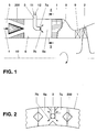
- Fig. 1 shows only the significant part of the annular combustion chamber 1, namely the vortex formation, the fuel lance leading to a temperature gradation and the turbine located downstream and to be acted upon.
- the main flow 4 is always a combustion air flow, the temperature and composition of which can be very different.
- the main flow 4 consists of compressed air which forms the combustion air; however, if the present ring combustion chamber 1 is connected to an upstream first combustion chamber and a first turbine, this main flow consists of still relatively hot exhaust gases, the temperature of which leads to self-ignition of the fuel injected there.
- the combustion air 4 thus flows into an inflow zone 5, which already on the inside and in the circumferential direction of the channel wall 6 with a number of vortex-generating elements 200 as vortex generators were named, which will be discussed in more detail below.
- the combustion air 4 is swirled by the vortex generators 200 such that no recirculation areas occur in the subsequent premixing and combustion zone 5a after the vortex generators 200 mentioned.
- a plurality of fuel lances 3 are arranged in the circumferential direction of this premixing and combustion zone 5a, which take over the supply of fuel 11 and supporting air 12.
- the supply of these media 11, 12 to the individual fuel lances 3 can be accomplished, for example, by a ring line, not shown.
- the swirl flow triggered individually by the vortex generators 200 is operatively connected to the sectorally injected fuel 7a, 7b, such that, by appropriately regulating the amount of fuel across the individual sectors, the individual vortex generators 200 have different levels of enrichment due to the effect of the vortex generators 200 Partial flows of the combustion air 4 result, which triggers a different temperature profile in the subsequent combustion.
- a temperature gradation 8 over the flow cross-section is shown graphically and qualitatively in the figure.
- this temperature-graded hot gas front acts on the rotor blades of a turbine 2 via corresponding guide vanes 9.
- the blade roots are calorically less stressed, but the remaining blade surface is subjected to a slightly higher temperature, so that for the Efficiency and the performance-determining mean hot gas temperature is maintained.
- FIG. 2 shows, for each fuel lance 3 in the area of the vortex generators 200, a chamber typical of an annular annular combustion chamber 1 is formed, with which side vortex generators 200 can also be attached. If the combustion chamber consists of individual tubes, such a subdivision is not necessary because the tube then also forms the chamber. Seen this way the fuel lance 3 is encased by vortex generators 200 in terms of flow.
- the sectoral fuel injection 7a, 7b is dependent on the position of the vortex generators 200 placed upstream, wherein this injection should preferably be directed between the individual flank surfaces of the vortex generators 200 to ensure a temperature gradation, so that the swirling that occurs there mixes well with the appropriate amount of fuel.
- the fuel injection 7a, 7b can also be accomplished via a larger number of nozzles, depending on the desired temperature grading and depending on the position of the individual vortex generators 200 within the flow cross-section of the annular combustion chamber 1.
- This annular combustion chamber can have a radial expansion consist of several superordinate rows of chambers, one row of chambers being designed as a pilot stage to the remaining concentrically arranged rows of chambers.
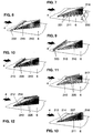
- a vortex generator 200, 201, 202 essentially consists of three freely flowing triangular surfaces. These are a roof surface 210 and two side surfaces 211 and 213. In their longitudinal extent, these surfaces run at certain angles in the direction of flow.
- the side walls of the vortex generators 200, 201, 202, which preferably consist of right-angled triangles, are fixed with their long sides on the channel wall 6 already mentioned, preferably gas-tight. They are oriented so that they form a joint on their narrow sides, including an arrow angle ⁇ .
- the push is designed as a sharp connecting edge 216 and is perpendicular to each channel wall 6 with which the side surfaces are flush.
- the two side surfaces 211, 213 including the arrow angle ⁇ are symmetrical in shape, size and orientation in FIG. 3, they are arranged on both sides of an axis of symmetry 217 which is oriented in the same direction as the channel axis.
- the roof surface 210 lies against the same channel wall 6 as the side surfaces 211, 213 with a very narrow edge 215 running transversely to the flow channel. Its longitudinal edges 212, 214 are flush with the longitudinal edges of the side surfaces 211 protruding into the flow channel , 213.
- the roof surface 210 extends at an angle of inclination ⁇ to the channel wall 6, the longitudinal edges 212, 214 of which, together with the connecting edge 216, form a point 218.
- the vortex generator 200, 201, 202 can also be provided with a bottom surface with which it is attached to the channel wall 6 in a suitable manner. Such a floor area is, however, unrelated to the mode of operation of the element.
- the mode of operation of the vortex generator 200, 201, 202 is as follows: When flowing around the edges 212 and 214, the main flow is converted into a pair of opposing vortices, as is schematically outlined in the figures.
- the vortex axes lie in the axis of the main flow.
- the number of swirls and the location of the vortex breakdown (vortex breakdown), if the latter is aimed for, are determined by appropriate selection of the angle of attack ⁇ and the arrow angle ⁇ .
- the vortex strength or the number of swirls is increased, and the location of the vortex bursting shifts upstream into the region of the vortex generator 200, 201, 202 itself.
- these two angles ⁇ and ⁇ are due to structural conditions and determined by the process itself.
- These vortex generators only have to be adjusted in terms of length and height, as will be explained in more detail below under FIG. 6.
- the connecting edge 216 of the two side surfaces 211, 213 forms the downstream edge of the vortex generator 200.
- the edge 215 of the roof surface 210 running transversely to the flow through the channel is thus the edge which is first acted upon by the channel flow.
- FIG. 4 shows a so-called half "vortex generator” based on a vortex generator according to FIG. 6.
- the vortex generator 201 shown here only one of the two side surfaces is provided with the arrow angle ⁇ / 2.
- the other side surface is straight and oriented in the direction of flow.
- only one vortex is generated on the arrowed side, as is shown in the figure. Accordingly, there is no vortex-neutral field downstream of this vortex generator, but a swirl is forced on the flow.
- FIG. 5 differs from FIG. 3 in that the sharp connecting edge 216 of the vortex generator 202 is the point which is first acted upon by the channel flow. The element is therefore rotated by 180 °. As can be seen from the illustration, the two opposite vortices have changed their sense of rotation.
- FIG. 6 shows the basic geometry of a vortex generator 200 installed in a channel 5.
- the height h of the connecting edge 216 will be coordinated with the channel height H, or the height of the channel part which is assigned to the vortex generator that the vortex generated immediately downstream of the vortex generator 200 already reaches such a size that the full channel height H is filled. This leads to a uniform speed distribution in the cross-section applied.
- a Another criterion that can influence the ratio of the two heights h / H to be selected is the pressure drop that occurs when the vortex generator 200 flows around. It goes without saying that the pressure loss coefficient also increases with a larger ratio h / H.
- the vortex generators 200, 201, 202 are mainly used when it comes to mixing two flows.
- the main flow 4 for example as hot gases, attacks the transverse edge 215 or the connecting edge 216 in the direction of the arrow.
- the secondary flow in the form of a gaseous and / or liquid fuel, which is possibly enriched with a portion of supporting air (see FIG. 1) a significantly smaller mass flow than the main flow. In the present case, this secondary flow is introduced into the main flow downstream of the vortex generator, as can be seen particularly well from FIG. 1.
- the vortex generators 200 are distributed at a distance over the circumference of a chamber of the channel 5.
- the vortex generators can also be strung together in the circumferential direction so that no gaps are left on the channel wall 6.
- the vortices to be generated are ultimately decisive for the choice of the number and the arrangement of the vortex generators.
- FIGS. 7-13 show further possible forms of introducing the fuel into the main flow 4. These variants can be combined in a variety of ways with one another and with a central fuel injection, as can be seen, for example, from FIG. 1.
- the fuel is also injected via wall bores 221 which are located directly next to the side surfaces 211, 213 and in their longitudinal extent in the same channel wall 6 on which the vortex generators are arranged.
- the introduction of the fuel through the wall bores 221 gives the generated vortices an additional impulse, which extends the lifespan of the vortex generator.
- the fuel is injected via a slot 222 or via wall bores 223, both precautions being located directly in front of the edge 215 of the roof surface 210 running transversely to the flow channel and in its longitudinal extent in the same channel wall 6 on which the Vortex generators are arranged.
- the geometry of the wall bores 223 or of the slot 222 is selected such that the fuel is introduced into the main flow 4 at a specific injection angle and largely shields the post-placed vortex generator as a protective film against the hot main flow 4 by flow around it.
- the secondary flow (cf. above) is first introduced into the hollow interior of the vortex generators via guides (not shown) through the channel wall 6. This creates an internal cooling facility for the vortex generators without providing any additional equipment.
- the fuel is injected via wall bores 224, which are located inside the roof surface 210 directly behind and along the edge 215 running transversely to the flow channel.
- the vortex generator is cooled here more externally than internally.
- the emerging secondary flow forms when flowing around the roof surface 210 a protective layer shielding it against the hot main flow 4.
- the fuel is injected via wall bores 225, which are staggered within the roof surface 210 along the line of symmetry 217.
- the channel walls 6 are particularly well protected from the hot main flow 4, since the fuel is first introduced on the outer circumference of the vortex.
- the fuel is injected via wall bores 226, which are located in the longitudinal edges 212, 214 of the roof surface 210.
- This solution ensures good cooling of the vortex generators, since the fuel escapes from its extremities and thus completely flushes the inner walls of the element.
- the secondary flow is fed directly into the resulting vortex, which leads to defined flow conditions.
- the injection takes place via wall bores 227, which are located in the side surfaces 211 and 213, on the one hand in the region of the longitudinal edges 212 and 214 and on the other hand in the region of the connecting edge 216.
- This variant is similar in effect to that from FIG. 7 (bores 221 ) and from Fig. 12 (bores 226).
Landscapes
- Engineering & Computer Science (AREA)
- Chemical & Material Sciences (AREA)
- Combustion & Propulsion (AREA)
- Mechanical Engineering (AREA)
- General Engineering & Computer Science (AREA)
- Combustion Of Fluid Fuel (AREA)
- Pressure-Spray And Ultrasonic-Wave- Spray Burners (AREA)
Applications Claiming Priority (2)
| Application Number | Priority Date | Filing Date | Title |
|---|---|---|---|
| DE4446611A DE4446611A1 (de) | 1994-12-24 | 1994-12-24 | Brennkammer |
| DE4446611 | 1994-12-24 |
Publications (3)
| Publication Number | Publication Date |
|---|---|
| EP0718558A2 true EP0718558A2 (fr) | 1996-06-26 |
| EP0718558A3 EP0718558A3 (fr) | 1997-04-23 |
| EP0718558B1 EP0718558B1 (fr) | 2001-04-18 |
Family
ID=6537131
Family Applications (1)
| Application Number | Title | Priority Date | Filing Date |
|---|---|---|---|
| EP95810761A Expired - Lifetime EP0718558B1 (fr) | 1994-12-24 | 1995-12-05 | Brûleur |
Country Status (5)
| Country | Link |
|---|---|
| US (1) | US5609030A (fr) |
| EP (1) | EP0718558B1 (fr) |
| JP (1) | JP3977454B2 (fr) |
| CN (1) | CN1076786C (fr) |
| DE (2) | DE4446611A1 (fr) |
Cited By (4)
| Publication number | Priority date | Publication date | Assignee | Title |
|---|---|---|---|---|
| EP1400752A1 (fr) * | 2002-09-20 | 2004-03-24 | Siemens Aktiengesellschaft | Brûleur à prémélange avec un écoulement d'air profilé |
| EP2112433A1 (fr) * | 2008-04-23 | 2009-10-28 | Siemens Aktiengesellschaft | Chambre de mélange |
| WO2013139914A1 (fr) * | 2012-03-23 | 2013-09-26 | Alstom Technology Ltd | Dispositif de combustion |
| US10072532B2 (en) | 2013-03-06 | 2018-09-11 | General Electric Technology Gmbh | Method for starting-up and operating a combined-cycle power plant |
Families Citing this family (21)
| Publication number | Priority date | Publication date | Assignee | Title |
|---|---|---|---|---|
| US5918465A (en) * | 1995-02-03 | 1999-07-06 | Bmw Rolls-Royce Gmbh | Flow guiding body for a gas turbine combustion chamber |
| JP2003035417A (ja) * | 2001-07-24 | 2003-02-07 | Mitsubishi Heavy Ind Ltd | ガスタービン燃焼器のパイロットノズル |
| DE10219354A1 (de) * | 2002-04-30 | 2003-11-13 | Rolls Royce Deutschland | Gasturbinenbrennkammer mit gezielter Kraftstoffeinbringung zur Verbesserung der Homogenität des Kraftstoff-Luft-Gemisches |
| US7810336B2 (en) * | 2005-06-03 | 2010-10-12 | Siemens Energy, Inc. | System for introducing fuel to a fluid flow upstream of a combustion area |
| DE102007043626A1 (de) | 2007-09-13 | 2009-03-19 | Rolls-Royce Deutschland Ltd & Co Kg | Gasturbinenmagerbrenner mit Kraftstoffdüse mit kontrollierter Kraftstoffinhomogenität |
| EP2257736B1 (fr) | 2008-03-07 | 2015-11-25 | Alstom Technology Ltd | Procédé de production de gaz chaud |
| EP2252831B1 (fr) | 2008-03-07 | 2013-05-08 | Alstom Technology Ltd | Ensemble brûleur et son utilisation |
| ES2400247T3 (es) * | 2008-12-19 | 2013-04-08 | Alstom Technology Ltd | Quemador de una turbina de gas que tiene una configuración de lanza especial |
| ATE554346T1 (de) | 2009-03-16 | 2012-05-15 | Alstom Technology Ltd | BRENNER FÜR EINE GASTURBINE UND VERFAHREN ZUR LOKALEN KÜHLUNG VON HEIßEN GASSTRÖMEN, DIE EINEN BRENNER DURCHLAUFEN |
| EP2253888B1 (fr) * | 2009-05-14 | 2013-10-16 | Alstom Technology Ltd | Brûleur d'une turbine à gaz ayant un générateur de vortex avec une lance à combustible |
| AU334043S (en) | 2010-07-15 | 2010-12-07 | Sharp Kk | Electronic calculator |
| EP2644997A1 (fr) * | 2012-03-26 | 2013-10-02 | Alstom Technology Ltd | Agencement de mélange pour mélanger un combustible avec un flux de gaz contenant de l'oxygène |
| DE102012213852A1 (de) * | 2012-08-06 | 2014-02-06 | Siemens Aktiengesellschaft | Lokale Verbesserung der Mischung von Luft und Brennstoff in Brennern mit Drallerzeugern |
| EP2789915A1 (fr) * | 2013-04-10 | 2014-10-15 | Alstom Technology Ltd | Procédé de fonctionnement d'une chambre de combustion et chambre de combustion |
| EP2894405B1 (fr) * | 2014-01-10 | 2016-11-23 | General Electric Technology GmbH | Dispositif à combustion séquentielle avec un gaz de dilution |
| EP3186558B1 (fr) | 2014-08-26 | 2020-06-24 | Siemens Energy, Inc. | Agencement de trous de refroidissement de film pour résonateurs acoustiques dans des moteurs à turbine à gaz |
| EP3081862B1 (fr) * | 2015-04-13 | 2020-08-19 | Ansaldo Energia Switzerland AG | Agencement de génération de vortex pour un brûleur à pré-mélange d'une turbine à gaz et turbine à gaz avec un tel agencement de génération de vortex |
| US12050012B2 (en) | 2020-03-31 | 2024-07-30 | Siemens Energy Global GmbH & Co. KG | Burner component of a burner, and burner of a gas turbine having a burner component of this type |
| US11384937B1 (en) * | 2021-05-12 | 2022-07-12 | General Electric Company | Swirler with integrated damper |
| US11454396B1 (en) * | 2021-06-07 | 2022-09-27 | General Electric Company | Fuel injector and pre-mixer system for a burner array |
| KR102667812B1 (ko) * | 2022-02-07 | 2024-05-20 | 두산에너빌리티 주식회사 | 연소기용 노즐 및 이를 포함하는 가스 터빈 |
Family Cites Families (16)
| Publication number | Priority date | Publication date | Assignee | Title |
|---|---|---|---|---|
| US2592748A (en) * | 1944-02-17 | 1952-04-15 | Rateau Soc | Annular combustion chamber with hollow air guide vanes with radial gasiform fuel slots for gas turbines |
| CH270346A (de) * | 1946-11-21 | 1950-08-31 | Power Jets Res & Dev Ltd | Einrichtung für die Verbrennung von Brennstoff in einem rasch strömenden Luftstrom. |
| US2607191A (en) * | 1947-11-28 | 1952-08-19 | United Aircraft Corp | Vortex producing mechanism for mixing combustion chamber fluids |
| US2999359A (en) * | 1956-04-25 | 1961-09-12 | Rolls Royce | Combustion equipment of gas-turbine engines |
| US3078672A (en) * | 1959-03-28 | 1963-02-26 | Maschf Augsburg Nuernberg Ag | Process and apparatus for operating a continuous or intermittent combustion engine |
| US3974646A (en) * | 1974-06-11 | 1976-08-17 | United Technologies Corporation | Turbofan engine with augmented combustion chamber using vorbix principle |
| US4199934A (en) * | 1975-07-24 | 1980-04-29 | Daimler-Benz Aktiengesellschaft | Combustion chamber, especially for gas turbines |
| US4197700A (en) * | 1976-10-13 | 1980-04-15 | Jahnig Charles E | Gas turbine power system with fuel injection and combustion catalyst |
| NL7801395A (nl) * | 1977-02-23 | 1978-08-25 | Foerenade Fabriksverken | Werkwijze en inrichting voor het verbranden van vloeibare, gasvormige of poedervormige brandstoffen. |
| US4821512A (en) * | 1987-05-05 | 1989-04-18 | United Technologies Corporation | Piloting igniter for supersonic combustor |
| US5076053A (en) * | 1989-08-10 | 1991-12-31 | United Technologies Corporation | Mechanism for accelerating heat release of combusting flows |
| JP2878831B2 (ja) * | 1990-11-30 | 1999-04-05 | 株式会社日立製作所 | ガスタービン燃焼器 |
| DE4304989A1 (de) * | 1993-02-18 | 1994-08-25 | Abb Management Ag | Verfahren zur Kühlung einer Gasturbinenanlage |
| CH687269A5 (de) * | 1993-04-08 | 1996-10-31 | Abb Management Ag | Gasturbogruppe. |
| EP0620403B1 (fr) * | 1993-04-08 | 1996-12-04 | ABB Management AG | Dispositif de mélange et de stabilisation de la flamme dans une chambre de combustion avec mélange préalable du combustible. |
| CH687827A5 (de) * | 1993-04-08 | 1997-02-28 | Asea Brown Boveri | Gasturbinenanlage mit einer Druckwellenmaschine. |
-
1994
- 1994-12-24 DE DE4446611A patent/DE4446611A1/de not_active Withdrawn
-
1995
- 1995-11-03 US US08/552,776 patent/US5609030A/en not_active Expired - Lifetime
- 1995-12-05 EP EP95810761A patent/EP0718558B1/fr not_active Expired - Lifetime
- 1995-12-05 DE DE59509206T patent/DE59509206D1/de not_active Expired - Lifetime
- 1995-12-19 CN CN95119890A patent/CN1076786C/zh not_active Expired - Fee Related
- 1995-12-20 JP JP33185195A patent/JP3977454B2/ja not_active Expired - Lifetime
Non-Patent Citations (1)
| Title |
|---|
| None |
Cited By (6)
| Publication number | Priority date | Publication date | Assignee | Title |
|---|---|---|---|---|
| EP1400752A1 (fr) * | 2002-09-20 | 2004-03-24 | Siemens Aktiengesellschaft | Brûleur à prémélange avec un écoulement d'air profilé |
| EP2112433A1 (fr) * | 2008-04-23 | 2009-10-28 | Siemens Aktiengesellschaft | Chambre de mélange |
| US8424310B2 (en) | 2008-04-23 | 2013-04-23 | Siemens Aktiengesellschaft | Mixing chamber |
| WO2013139914A1 (fr) * | 2012-03-23 | 2013-09-26 | Alstom Technology Ltd | Dispositif de combustion |
| US9568198B2 (en) | 2012-03-23 | 2017-02-14 | General Electric Technology Gmbh | Combustion device having a distribution plenum |
| US10072532B2 (en) | 2013-03-06 | 2018-09-11 | General Electric Technology Gmbh | Method for starting-up and operating a combined-cycle power plant |
Also Published As
| Publication number | Publication date |
|---|---|
| DE4446611A1 (de) | 1996-06-27 |
| CN1076786C (zh) | 2001-12-26 |
| EP0718558A3 (fr) | 1997-04-23 |
| JPH08226647A (ja) | 1996-09-03 |
| US5609030A (en) | 1997-03-11 |
| EP0718558B1 (fr) | 2001-04-18 |
| CN1130718A (zh) | 1996-09-11 |
| JP3977454B2 (ja) | 2007-09-19 |
| DE59509206D1 (de) | 2001-05-23 |
Similar Documents
| Publication | Publication Date | Title |
|---|---|---|
| EP0718558B1 (fr) | Brûleur | |
| EP0745809B1 (fr) | Générateur de tourbillons pour chambre de combustion | |
| DE4426351B4 (de) | Brennkammer für eine Gasturbine | |
| EP0687860B1 (fr) | Chambre de combustion à allumage automatique | |
| DE2338673C2 (de) | Nachbrenneranordnung für ein Gasturbinenstrahltriebwerk | |
| EP0619457B1 (fr) | Brûleur à prémélange | |
| EP0623786B1 (fr) | Chambre de combustion | |
| DE102007004864B4 (de) | Brennkammer einer Gasturbine und Verbrennungssteuerverfahren für eine Gasturbine | |
| DE60310170T2 (de) | Brennstoffinjektionsvorrichtung | |
| EP0675322B1 (fr) | Brûleur à prémélange | |
| EP1654496B1 (fr) | Bruleur et procede pour faire fonctionner une turbine a gaz | |
| EP0620403B1 (fr) | Dispositif de mélange et de stabilisation de la flamme dans une chambre de combustion avec mélange préalable du combustible. | |
| EP0718561B1 (fr) | Brûleur | |
| EP0733861A2 (fr) | Chambre de combustion à combustion étagée | |
| EP2006606A1 (fr) | Stabilisation sans tourbillonner de la flamme d'un brûleur à prémélange | |
| DE112019000871T5 (de) | Brennkammer und damit ausgestattete gasturbine | |
| EP1754002B1 (fr) | Brûleur étagé à prémélange comprenant in injecteur de carburant liquide | |
| WO2012016748A2 (fr) | Chambre de combustion de turbine à gaz | |
| EP2171354B1 (fr) | Brûleur | |
| DE19507088B4 (de) | Vormischbrenner | |
| DE4404389A1 (de) | Brennkammer mit Selbstzündung | |
| CH687827A5 (de) | Gasturbinenanlage mit einer Druckwellenmaschine. | |
| DE19527452A1 (de) | Mehrstufige Dampfturbine | |
| EP2199681A1 (fr) | Chambre de combustion de turbine à gaz et turbine à gaz |
Legal Events
| Date | Code | Title | Description |
|---|---|---|---|
| PUAI | Public reference made under article 153(3) epc to a published international application that has entered the european phase |
Free format text: ORIGINAL CODE: 0009012 |
|
| AK | Designated contracting states |
Kind code of ref document: A2 Designated state(s): DE FR GB NL |
|
| RAP1 | Party data changed (applicant data changed or rights of an application transferred) |
Owner name: ASEA BROWN BOVERI AG |
|
| PUAL | Search report despatched |
Free format text: ORIGINAL CODE: 0009013 |
|
| AK | Designated contracting states |
Kind code of ref document: A3 Designated state(s): DE FR GB NL |
|
| 17P | Request for examination filed |
Effective date: 19970913 |
|
| 17Q | First examination report despatched |
Effective date: 19990818 |
|
| GRAG | Despatch of communication of intention to grant |
Free format text: ORIGINAL CODE: EPIDOS AGRA |
|
| GRAG | Despatch of communication of intention to grant |
Free format text: ORIGINAL CODE: EPIDOS AGRA |
|
| GRAG | Despatch of communication of intention to grant |
Free format text: ORIGINAL CODE: EPIDOS AGRA |
|
| GRAH | Despatch of communication of intention to grant a patent |
Free format text: ORIGINAL CODE: EPIDOS IGRA |
|
| RAP1 | Party data changed (applicant data changed or rights of an application transferred) |
Owner name: ABB (SCHWEIZ) AG |
|
| GRAH | Despatch of communication of intention to grant a patent |
Free format text: ORIGINAL CODE: EPIDOS IGRA |
|
| GRAA | (expected) grant |
Free format text: ORIGINAL CODE: 0009210 |
|
| AK | Designated contracting states |
Kind code of ref document: B1 Designated state(s): DE FR GB NL |
|
| REF | Corresponds to: |
Ref document number: 59509206 Country of ref document: DE Date of ref document: 20010523 |
|
| ET | Fr: translation filed | ||
| GBT | Gb: translation of ep patent filed (gb section 77(6)(a)/1977) |
Effective date: 20010709 |
|
| REG | Reference to a national code |
Ref country code: GB Ref legal event code: IF02 |
|
| PLBE | No opposition filed within time limit |
Free format text: ORIGINAL CODE: 0009261 |
|
| STAA | Information on the status of an ep patent application or granted ep patent |
Free format text: STATUS: NO OPPOSITION FILED WITHIN TIME LIMIT |
|
| 26N | No opposition filed | ||
| REG | Reference to a national code |
Ref country code: GB Ref legal event code: 732E |
|
| NLS | Nl: assignments of ep-patents |
Owner name: ALSTOM (SWITZERLAND) LTD |
|
| NLT1 | Nl: modifications of names registered in virtue of documents presented to the patent office pursuant to art. 16 a, paragraph 1 |
Owner name: ABB SCHWEIZ HOLDING AG |
|
| REG | Reference to a national code |
Ref country code: FR Ref legal event code: CD |
|
| PGFP | Annual fee paid to national office [announced via postgrant information from national office to epo] |
Ref country code: NL Payment date: 20091222 Year of fee payment: 15 |
|
| PGFP | Annual fee paid to national office [announced via postgrant information from national office to epo] |
Ref country code: GB Payment date: 20091106 Year of fee payment: 15 Ref country code: FR Payment date: 20091215 Year of fee payment: 15 |
|
| PGFP | Annual fee paid to national office [announced via postgrant information from national office to epo] |
Ref country code: DE Payment date: 20091230 Year of fee payment: 15 |
|
| PG25 | Lapsed in a contracting state [announced via postgrant information from national office to epo] |
Ref country code: DE Free format text: LAPSE BECAUSE OF THE APPLICANT RENOUNCES Effective date: 20101025 |
|
| REG | Reference to a national code |
Ref country code: NL Ref legal event code: V1 Effective date: 20110701 |
|
| GBPC | Gb: european patent ceased through non-payment of renewal fee |
Effective date: 20101205 |
|
| REG | Reference to a national code |
Ref country code: FR Ref legal event code: ST Effective date: 20110831 |
|
| PG25 | Lapsed in a contracting state [announced via postgrant information from national office to epo] |
Ref country code: FR Free format text: LAPSE BECAUSE OF NON-PAYMENT OF DUE FEES Effective date: 20110103 |
|
| PG25 | Lapsed in a contracting state [announced via postgrant information from national office to epo] |
Ref country code: GB Free format text: LAPSE BECAUSE OF NON-PAYMENT OF DUE FEES Effective date: 20101205 |
|
| PG25 | Lapsed in a contracting state [announced via postgrant information from national office to epo] |
Ref country code: NL Free format text: LAPSE BECAUSE OF NON-PAYMENT OF DUE FEES Effective date: 20110701 |