EP0718560B1 - Chambre de combustion à deux têtes fonctionnant du ralenti au plein gaz - Google Patents
Chambre de combustion à deux têtes fonctionnant du ralenti au plein gaz Download PDFInfo
- Publication number
- EP0718560B1 EP0718560B1 EP95402626A EP95402626A EP0718560B1 EP 0718560 B1 EP0718560 B1 EP 0718560B1 EP 95402626 A EP95402626 A EP 95402626A EP 95402626 A EP95402626 A EP 95402626A EP 0718560 B1 EP0718560 B1 EP 0718560B1
- Authority
- EP
- European Patent Office
- Prior art keywords
- injectors
- permeability
- combustion chamber
- head
- take
- Prior art date
- Legal status (The legal status is an assumption and is not a legal conclusion. Google has not performed a legal analysis and makes no representation as to the accuracy of the status listed.)
- Expired - Lifetime
Links
Images


Classifications
-
- F—MECHANICAL ENGINEERING; LIGHTING; HEATING; WEAPONS; BLASTING
- F23—COMBUSTION APPARATUS; COMBUSTION PROCESSES
- F23R—GENERATING COMBUSTION PRODUCTS OF HIGH PRESSURE OR HIGH VELOCITY, e.g. GAS-TURBINE COMBUSTION CHAMBERS
- F23R3/00—Continuous combustion chambers using liquid or gaseous fuel
- F23R3/42—Continuous combustion chambers using liquid or gaseous fuel characterised by the arrangement or form of the flame tubes or combustion chambers
- F23R3/50—Combustion chambers comprising an annular flame tube within an annular casing
-
- F—MECHANICAL ENGINEERING; LIGHTING; HEATING; WEAPONS; BLASTING
- F23—COMBUSTION APPARATUS; COMBUSTION PROCESSES
- F23R—GENERATING COMBUSTION PRODUCTS OF HIGH PRESSURE OR HIGH VELOCITY, e.g. GAS-TURBINE COMBUSTION CHAMBERS
- F23R3/00—Continuous combustion chambers using liquid or gaseous fuel
- F23R3/02—Continuous combustion chambers using liquid or gaseous fuel characterised by the air-flow or gas-flow configuration
- F23R3/04—Air inlet arrangements
- F23R3/10—Air inlet arrangements for primary air
-
- F—MECHANICAL ENGINEERING; LIGHTING; HEATING; WEAPONS; BLASTING
- F23—COMBUSTION APPARATUS; COMBUSTION PROCESSES
- F23R—GENERATING COMBUSTION PRODUCTS OF HIGH PRESSURE OR HIGH VELOCITY, e.g. GAS-TURBINE COMBUSTION CHAMBERS
- F23R3/00—Continuous combustion chambers using liquid or gaseous fuel
- F23R3/28—Continuous combustion chambers using liquid or gaseous fuel characterised by the fuel supply
- F23R3/34—Feeding into different combustion zones
Definitions
- the present invention relates to an annular combustion chamber comprising axial walls joined by a chamber bottom and several fuel injectors arranged in holes passing through the chamber bottom, said injectors being distributed over a pilot head and over a take-off head radially spaced from the pilot head, said combustion chamber having a general direction of gas flow.
- These chambers can either have the pilot head externally and the internal take-off head, or vice versa, the external take-off head and the pilot head near the motor axis.
- the take-off head is used at full throttle and is not not supplied with fuel at idle speed.
- GB 2 269 449 describes a two-head combustion chamber where the injectors of takeoffs and pilot injectors are staggered on both heads. he is not provided in this patent for operating both types simultaneously injectors.
- GB 2 003 554 describes a combustion chamber with two heads An internal head suitable for idling and a much shorter external head suitable for cruising or takeoff regimes. Both heads work separately.
- the aim of the present invention is to optimize the radial profile of the outlet chamber temperatures. Another goal is to improve the chamber operation at idle speed.
- the pilot head being equipped with N idle injectors, permeability P1, adapted to the idling speed;
- This arrangement also allows the use of an ignition system. conventional regardless of the position of the pilot head, even if it is placed internally.
- the P2 permeability take-off injectors are ignited by flame spread from a high compressor speed pressure substantially equal to 70% of the nominal speed at full speed, and operate until full throttle.
- the permeability P1 is understood between 10% and 12% of the air flow W36 which enters the combustion chamber, and the permeability P2 is between 26% and 35% of the same air flow. This range of values for P2 ensures take-off injectors are ignited by flame spread and minimum smoke and NOx emissions at full throttle.
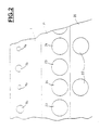
- the gas turbine combustion chamber shown in the drawings is of annular type. It is delimited by an external annular wall 1, a internal annular wall 2, a transverse chamber bottom 3 joining the walls 1 and 2.
- the chamber bottom 3 is pierced with several orifices 4 inside each of which is placed an injection system.
- the reference 5 represents a diffuser arranged at the outlet of a high pressure compressor which diffuses an air flow A in a space annular 6 delimited by an external casing 7 and an internal casing 8.
- the chamber combustion is arranged in the annular space 6 away from the casings 7 and 8.
- a part W36 of the air flow A enters the primary zone P of the combustion chamber by injection systems and by primary orifices 9 and 10 formed in walls 1 and 2.
- the reference 11a represents the general direction of the gas flow in the combustion chamber.
- the bottom of the chamber 3 has three separate portions.
- the inner portion 14 is located opposite the diffuser 5.
- the fuel injectors mounted in the orifices 4 of the inner portion 14 constitute the pilot head 20, while the fuel injectors mounted in the orifices 4 of the portion outside 12 constitute the takeoff head 21.
- the interior portion 14 equipped with the injectors will be called the pilot head. 20 while the outer portion 12 equipped with these injectors will be called take-off head 21.
- the pilot head 20 comprises N injectors 22 of permeability P1, and according to the invention, the take-off head comprises, alternately, N injectors 23 of permeability P1 and N injectors 24 of permeability P2.
- 22 ct 23 injectors, P1 permeability are staggered in the bottom of chamber 3, in other words the injectors 24 of permeability P2 are located in planes passing through the axis of the combustion chamber and through the injectors 22 of the pilot head 20.
- the injectors 22 and 23, of permeability P1 are suitable for the idling, while the injectors 24, of permeability P2 are suitable for full gas operation.
- the combustion chamber is lit and stabilized on the ground with the P1 permeability injection systems.
- the staggered arrangement of these injectors allows the use of a conventional ignition system although the pilot head is placed internally by adding to the axis of the combustion.
- P2 permeability i.e. the air flow rate passing through the injectors 24, is greater than the permeability P1 of the injectors 22 and 23.
- P2 permeation injection systems are switched on by flame spread from a high compressor speed pressure equal to 70% of the nominal speed of this compressor at high speed and run until full throttle.
- the primary orifices 9 formed in the external wall 1 are arranged in planes passing through the axis of the combustion chamber and through the injectors 23 and 24 of the takeoff head 21.
- the orifices 9a arranged opposite the P2 permeability injectors 24 have sections smaller than the section of orifices 9b located opposite the injectors 23 of permeability P1, in order to have in the primary zone P an identical local richness downstream of the orifices 9a and 9b.
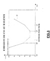
- Figure 3 shows the curve 30 of CO emissions at idle in depending on the richness in the injector. This curve 30 shows that the wealth in the PHI injector must be between 0.9 and 1.3.
- the curves 40, 41 and 42 represent the curves of operation of the P1 permeability injection systems at idle, in as a function of the PHI richness in the injector, and of the distribution of the charges between the pilot head and the take-off head.
- Curve 40 corresponds to a permeability P1 equal to 10% of W36
- curve 41 to a permeability P1 equal at 12.3% of W36
- the curve 42 at a permeability P1 equal to 14.6% of W36.
- the surface 43 located below the horizontal line 44 corresponds to flame extinction conditions, the richness in the primary zone P being too low ( ⁇ 20%).
- Figure 4 shows that the P1 permeability of systems of idling injection must be greater than 12% of W36 to satisfy the criteria 4 and 5 defined above.
- Figures 5 and 6 show the operating curves of the systems injection permeability P1, at start-up, as a function of the richness PHI in the injector, and the fuel flow per injector.
- Curve 50 corresponds at a permeability P1 of 8% of W36
- the curves 51, 52, 53, 54 correspond respectively to P1 permeabilities of 10%, 12%, 14% and 16% from W36.
- the permeability P1 must be greater than 10% of W36.
- FIG. 5 relates to a combustion chamber equipping a turbomachine whose starter provides ventilation greater than 55% of the reduced nominal chamber flow
- FIG. 6 relates to a combustion fitted to a turbomachine whose starter provides ventilation greater than 65% of the reduced nominal chamber flow.
- the hatched surface 60 shows the position of the operating points at startup which allow a good compromise between the five defined criteria above.
- the permeability P1 must be between 10% and 12% of W36, and, preferably, between 11% and 12% of W36.
- P2 permeability injection systems 24 must be dimensioned to ensure ignition by propagation of the flame and to have minimum smoke and NOx emissions at full gas.
- the permeability P2 is preferably between 26% and 35% of W36.
- the room configuration described above provides a profile efficient temperature radial from idle to full throttle and using a system conventional ignition although the pilot head 20 is in the internal position.
Landscapes
- Engineering & Computer Science (AREA)
- Chemical & Material Sciences (AREA)
- Combustion & Propulsion (AREA)
- Mechanical Engineering (AREA)
- General Engineering & Computer Science (AREA)
- Combustion Methods Of Internal-Combustion Engines (AREA)
Description
- la tête de décollage est également équipée de N injecteurs de ralenti, de perméabilité P1, adaptés au régime de ralenti, et, en alternance de N injecteurs de décollage, de perméabilité P2>P1, adaptés au régime de pleine charge, et
- suivant une vue de fond de chambre depuis l'intérieur de la chambre de combustion, parallèlement à ladite direction d'écoulement, les injecteurs de carburant de perméabilité P1, de la tête pilote et de la tête de décollage sont disposés sensiblement en quinconce.
- la figure 1 est une coupe axiale d'une chambre de combustion conforme à l'invention;
- la figure 2 est une vue partielle du fond de chambre, prise de l'intérieur de la chambre, parallèlement à la direction de l'écoulement des gaz ;
- la figure 3 est la courbe représentative de l'émission de l'oxyde de carbone au ralenti en fonction de la richesse de l'injecteur ;
- la figure 4 montre les points de fonctionnement d'une chambre de combustion à deux têtes, au ralenti, en fonction de la richesse des injecteurs de ralenti, de la répartition des charges entre la tête de décollage et la tête de ralenti et de la perméabilité P1 des injecteurs de ralenti ;
- la figure 5 montre les points de fonctionnement d'une chambre de combustion à deux têtes, lors de l'allumage, le rapport d'équivalence de l'injecteur étant de 55 % du débit réduit nominal, en fonction de la richesse des injecteurs à l'allumage, du débit de carburant par injecteur, et de la perméabilité P1 des injecteurs de ralenti ;
- la figure 6 est semblable à la figure 5, le rapport d'équivalence étant de 65 % du débit réduit nominal.
Claims (4)
- Chambre de combustion annulaire comportant des parois axiales (1, 2) réunies par un fond de chambre (3) et plusieurs injecteurs de carburant disposés dans des trous (4) traversant le tond de chambre (3), lesdits injecteurs étant répartis sur une portion intérieure (14) constituant une tête pilote (20) et sur une portion extérieure (12) constituant une tête de décollage (21) radialement espacée de la tète pilote (20). ladite chambre de combustion possédant une direction générale (11) d'écoulement des gaz,
la tête pilote (20) étant équipée de N injecteurs de ralenti (22), de perméabilité P1, adaptés aux régimes de ralenti; caractérisée par le fait que la tête de décollage (21) est équipée. en alternance, de N injecteurs de ralenti (23) de perméabilité P1, adaptés au régime de ralenti, et de N injecteurs de décollage (24), de perméabilité P2>P1, adaptés au régime de pleine charge, et par le fait que, suivant une vue de fond de chambre (3) depuis l'intérieur de la chambre de combustion, parallèlement à ladite direction d'écoulement (11), les injecteurs de carburant (22, 23) de perméabilité P1 de la tête pilote (20) et de la tête de décollage (21) sont disposés sensiblement en quinconce. - Chambre de combustion selon la revendication 1, caractérisée par le fait que la perméabilité P1 est comprise entre 10% et 12% du débit d'air W36 qui entre dans ladite chambre de combustion.
- Chambre de combustion selon l'une des revendications 1 ou 2, caractérisée par le fait que la perméabilité P2 est comprise entre 26% et 35% du débit d'air W36 qui entre dans ladite chambre.
- Chambre de combustion selon l'une des revendications 1 ou 2, caractérisée par le fait que la paroi axiale externe (1) comporte des orifices primaires (9a, 9b) pour l'introduction d'air primaire dans ladite chambre, lesdits orifices étant situés dans des plans passant par l'axe de ladite chambre de combustion et les injecteurs de carburant (23, 24) de la tête de décollage, et par le fait que les orifices (9a) en regard des injecteurs (24) de perméabilité P2 ont des sections inférieures aux sections des orifices (9b) disposes en regard des injecteurs (23) de perméabilité P1, afin d'avoir une richesse locale identique en aval desdits orifices.
Applications Claiming Priority (2)
| Application Number | Priority Date | Filing Date | Title |
|---|---|---|---|
| FR9414014A FR2727193B1 (fr) | 1994-11-23 | 1994-11-23 | Chambre de combustion a deux tetes fonctionnant du ralenti au plein gaz |
| FR9414014 | 1994-11-23 |
Publications (2)
| Publication Number | Publication Date |
|---|---|
| EP0718560A1 EP0718560A1 (fr) | 1996-06-26 |
| EP0718560B1 true EP0718560B1 (fr) | 2000-01-05 |
Family
ID=9469057
Family Applications (1)
| Application Number | Title | Priority Date | Filing Date |
|---|---|---|---|
| EP95402626A Expired - Lifetime EP0718560B1 (fr) | 1994-11-23 | 1995-11-22 | Chambre de combustion à deux têtes fonctionnant du ralenti au plein gaz |
Country Status (4)
| Country | Link |
|---|---|
| US (1) | US5642621A (fr) |
| EP (1) | EP0718560B1 (fr) |
| DE (1) | DE69514321T2 (fr) |
| FR (1) | FR2727193B1 (fr) |
Families Citing this family (8)
| Publication number | Priority date | Publication date | Assignee | Title |
|---|---|---|---|---|
| FR2770283B1 (fr) * | 1997-10-29 | 1999-11-19 | Snecma | Chambre de combustion pour turbomachine |
| DE10020598A1 (de) * | 2000-04-27 | 2002-03-07 | Rolls Royce Deutschland | Gasturbinenbrennkammer mit Zuleitungsöffnungen |
| FR2817017B1 (fr) * | 2000-11-21 | 2003-03-07 | Snecma Moteurs | Refroidissement integral des injecteurs de decollage d'une chambre de combustion a deux tetes |
| FR2829228B1 (fr) * | 2001-08-28 | 2005-07-15 | Snecma Moteurs | Chambre de combustion annulaire a double tete etagee |
| FR2958014B1 (fr) | 2010-03-23 | 2013-12-13 | Snecma | Chambre de combustion a injecteurs decales longitudinalement sur une meme couronne |
| EP2434222B1 (fr) | 2010-09-24 | 2019-02-27 | Ansaldo Energia IP UK Limited | Méthode d'opération d'une chambre de combustion |
| RU2493491C1 (ru) * | 2012-04-26 | 2013-09-20 | Федеральное государственное бюджетное учреждение науки Институт химической физики им. Н.Н. Семенова Российской академии наук (ИХФ РАН) | Способ сжигания топлива в камере сгорания газотурбинной установки и устройство для его реализации |
| US10670267B2 (en) * | 2015-08-14 | 2020-06-02 | Raytheon Technologies Corporation | Combustor hole arrangement for gas turbine engine |
Family Cites Families (10)
| Publication number | Priority date | Publication date | Assignee | Title |
|---|---|---|---|---|
| US4012904A (en) * | 1975-07-17 | 1977-03-22 | Chrysler Corporation | Gas turbine burner |
| FR2402068A1 (fr) * | 1977-09-02 | 1979-03-30 | Snecma | Chambre de combustion anti-pollution |
| US4194358A (en) * | 1977-12-15 | 1980-03-25 | General Electric Company | Double annular combustor configuration |
| GB2030653B (en) * | 1978-10-02 | 1983-05-05 | Gen Electric | Gas turbine engine combustion gas temperature variation |
| US4292801A (en) * | 1979-07-11 | 1981-10-06 | General Electric Company | Dual stage-dual mode low nox combustor |
| US5284019A (en) * | 1990-06-12 | 1994-02-08 | The United States Of America As Represented By The Secretary Of The Air Force | Double dome, single anular combustor with daisy mixer |
| US5406799A (en) * | 1992-06-12 | 1995-04-18 | United Technologies Corporation | Combustion chamber |
| FR2694624B1 (fr) * | 1992-08-05 | 1994-09-23 | Snecma | Chambre de combustion à plusieurs injecteurs de carburant. |
| US5323604A (en) * | 1992-11-16 | 1994-06-28 | General Electric Company | Triple annular combustor for gas turbine engine |
| FR2698157B1 (fr) * | 1992-11-18 | 1994-12-16 | Snecma | Système d'injection aérodynamique de chambre de combustion. |
-
1994
- 1994-11-23 FR FR9414014A patent/FR2727193B1/fr not_active Expired - Fee Related
-
1995
- 1995-11-21 US US08/561,275 patent/US5642621A/en not_active Expired - Lifetime
- 1995-11-22 EP EP95402626A patent/EP0718560B1/fr not_active Expired - Lifetime
- 1995-11-22 DE DE69514321T patent/DE69514321T2/de not_active Expired - Lifetime
Also Published As
| Publication number | Publication date |
|---|---|
| DE69514321D1 (de) | 2000-02-10 |
| EP0718560A1 (fr) | 1996-06-26 |
| DE69514321T2 (de) | 2000-06-08 |
| FR2727193B1 (fr) | 1996-12-20 |
| FR2727193A1 (fr) | 1996-05-24 |
| US5642621A (en) | 1997-07-01 |
Similar Documents
| Publication | Publication Date | Title |
|---|---|---|
| EP2042806B1 (fr) | Chambre de combustion d'une turbomachine | |
| CA2588952C (fr) | Chambre de combustion d'une turbomachine | |
| EP1288579B1 (fr) | Chambre de combustion annulaire à double tête étagée | |
| CA2634615C (fr) | Chambre de combustion de turbomachine a circulation helicoidale de l'air | |
| FR2941287A1 (fr) | Paroi de chambre de combustion de turbomachine a une seule rangee annulaire d'orifices d'entree d'air primaire et de dilution | |
| FR2930591A1 (fr) | Optimisation du positionnement angulaire d'un distributeur de turbine en sortie d'une chambre de combustion de turbomachine | |
| EP0718560B1 (fr) | Chambre de combustion à deux têtes fonctionnant du ralenti au plein gaz | |
| WO2013060985A1 (fr) | Module de chambre de combustion de turbomachine d'aéronef et procédé de conception de celui-ci | |
| EP3286500B1 (fr) | Chambre de combustion de turbomachine comportant un dispositif de guidage de flux d'air de forme spécifique | |
| FR2694799A1 (fr) | Chambre de combustion annulaire conventionnelle à plusieurs injecteurs. | |
| EP4519607B1 (fr) | Procédé d'injection de mélange hydrogene-air pour brûleur de turbomachine | |
| EP0718559B1 (fr) | Système d'injection d'une chambre de combustion à deux têtes | |
| FR2948987A1 (fr) | Chambre de combustion de turbomachine comportant des orifices d'entree d'air ameliores | |
| EP4004443B1 (fr) | Chambre de combustion comportant des systèmes d'injection secondaires et procédé d'alimentation en carburant | |
| WO2018134501A2 (fr) | Chambre de combustion de turbomachine a haute permeabilite | |
| FR2996287A1 (fr) | Dispositif d'injection pour une chambre de combustion de turbomachine | |
| WO2023057722A1 (fr) | Dispositif d'injection de dihydrogène et d'air | |
| EP4327023B1 (fr) | Cône de diffusion pour partie arrière de turboréacteur intégrant un anneau accroche-flamme en bord de fuite | |
| FR3162499A1 (fr) | Dispositif d’injection avec injecteur avec combustion riche-pauvre pour chambre de combustion | |
| WO2025168900A1 (fr) | Système d'injection d'hydrogène et d'air | |
| WO2026022429A1 (fr) | Dispositif d'injection de carburant | |
| WO2025242981A1 (fr) | Injecteur ondulé de dispositif d'injection pour chambre de combustion | |
| FR3105985A1 (fr) | Circuit multipoint d’injecteur amélioré | |
| FR3094777A1 (fr) | Chambre de combustion principale de turboréacteur équipée d’une grille en aval de ses bruleurs | |
| FR3087876A1 (fr) | Ensemble pour chambre de combustion |
Legal Events
| Date | Code | Title | Description |
|---|---|---|---|
| PUAI | Public reference made under article 153(3) epc to a published international application that has entered the european phase |
Free format text: ORIGINAL CODE: 0009012 |
|
| 17P | Request for examination filed |
Effective date: 19951220 |
|
| AK | Designated contracting states |
Kind code of ref document: A1 Designated state(s): DE FR GB |
|
| 17Q | First examination report despatched |
Effective date: 19980722 |
|
| GRAG | Despatch of communication of intention to grant |
Free format text: ORIGINAL CODE: EPIDOS AGRA |
|
| GRAG | Despatch of communication of intention to grant |
Free format text: ORIGINAL CODE: EPIDOS AGRA |
|
| GRAH | Despatch of communication of intention to grant a patent |
Free format text: ORIGINAL CODE: EPIDOS IGRA |
|
| GRAH | Despatch of communication of intention to grant a patent |
Free format text: ORIGINAL CODE: EPIDOS IGRA |
|
| GRAA | (expected) grant |
Free format text: ORIGINAL CODE: 0009210 |
|
| AK | Designated contracting states |
Kind code of ref document: B1 Designated state(s): DE FR GB |
|
| REF | Corresponds to: |
Ref document number: 69514321 Country of ref document: DE Date of ref document: 20000210 |
|
| GBT | Gb: translation of ep patent filed (gb section 77(6)(a)/1977) |
Effective date: 20000131 |
|
| PLBE | No opposition filed within time limit |
Free format text: ORIGINAL CODE: 0009261 |
|
| STAA | Information on the status of an ep patent application or granted ep patent |
Free format text: STATUS: NO OPPOSITION FILED WITHIN TIME LIMIT |
|
| 26N | No opposition filed | ||
| REG | Reference to a national code |
Ref country code: GB Ref legal event code: IF02 |
|
| REG | Reference to a national code |
Ref country code: FR Ref legal event code: TP Ref country code: FR Ref legal event code: CD |
|
| REG | Reference to a national code |
Ref country code: FR Ref legal event code: CD |
|
| REG | Reference to a national code |
Ref country code: GB Ref legal event code: 732E Free format text: REGISTERED BETWEEN 20120517 AND 20120523 |
|
| PGFP | Annual fee paid to national office [announced via postgrant information from national office to epo] |
Ref country code: GB Payment date: 20131025 Year of fee payment: 19 Ref country code: DE Payment date: 20131022 Year of fee payment: 19 |
|
| PGFP | Annual fee paid to national office [announced via postgrant information from national office to epo] |
Ref country code: FR Payment date: 20141120 Year of fee payment: 20 |
|
| REG | Reference to a national code |
Ref country code: DE Ref legal event code: R119 Ref document number: 69514321 Country of ref document: DE |
|
| GBPC | Gb: european patent ceased through non-payment of renewal fee |
Effective date: 20141122 |
|
| PG25 | Lapsed in a contracting state [announced via postgrant information from national office to epo] |
Ref country code: GB Free format text: LAPSE BECAUSE OF NON-PAYMENT OF DUE FEES Effective date: 20141122 Ref country code: DE Free format text: LAPSE BECAUSE OF NON-PAYMENT OF DUE FEES Effective date: 20150602 |