EP0718926A2 - Modular Kreuzschaltungssystem - Google Patents
Modular Kreuzschaltungssystem Download PDFInfo
- Publication number
- EP0718926A2 EP0718926A2 EP95308831A EP95308831A EP0718926A2 EP 0718926 A2 EP0718926 A2 EP 0718926A2 EP 95308831 A EP95308831 A EP 95308831A EP 95308831 A EP95308831 A EP 95308831A EP 0718926 A2 EP0718926 A2 EP 0718926A2
- Authority
- EP
- European Patent Office
- Prior art keywords
- connector
- block
- panel
- connector block
- connectors
- Prior art date
- Legal status (The legal status is an assumption and is not a legal conclusion. Google has not performed a legal analysis and makes no representation as to the accuracy of the status listed.)
- Granted
Links
Images



Classifications
-
- H—ELECTRICITY
- H01—ELECTRIC ELEMENTS
- H01R—ELECTRICALLY-CONDUCTIVE CONNECTIONS; STRUCTURAL ASSOCIATIONS OF A PLURALITY OF MUTUALLY-INSULATED ELECTRICAL CONNECTING ELEMENTS; COUPLING DEVICES; CURRENT COLLECTORS
- H01R13/00—Details of coupling devices of the kinds covered by groups H01R12/70 or H01R24/00 - H01R33/00
- H01R13/73—Means for mounting coupling parts to apparatus or structures, e.g. to a wall
- H01R13/74—Means for mounting coupling parts in openings of a panel
-
- H—ELECTRICITY
- H01—ELECTRIC ELEMENTS
- H01R—ELECTRICALLY-CONDUCTIVE CONNECTIONS; STRUCTURAL ASSOCIATIONS OF A PLURALITY OF MUTUALLY-INSULATED ELECTRICAL CONNECTING ELEMENTS; COUPLING DEVICES; CURRENT COLLECTORS
- H01R13/00—Details of coupling devices of the kinds covered by groups H01R12/70 or H01R24/00 - H01R33/00
- H01R13/46—Bases; Cases
- H01R13/516—Means for holding or embracing insulating body, e.g. casing, hoods
- H01R13/518—Means for holding or embracing insulating body, e.g. casing, hoods for holding or embracing several coupling parts, e.g. frames
-
- G—PHYSICS
- G02—OPTICS
- G02B—OPTICAL ELEMENTS, SYSTEMS OR APPARATUS
- G02B6/00—Light guides; Structural details of arrangements comprising light guides and other optical elements, e.g. couplings
- G02B6/44—Mechanical structures for providing tensile strength and external protection for fibres, e.g. optical transmission cables
- G02B6/4439—Auxiliary devices
- G02B6/444—Systems or boxes with surplus lengths
- G02B6/4452—Distribution frames
- G02B6/44524—Distribution frames with frame parts or auxiliary devices mounted on the frame and collectively not covering a whole width of the frame or rack
-
- H—ELECTRICITY
- H01—ELECTRIC ELEMENTS
- H01R—ELECTRICALLY-CONDUCTIVE CONNECTIONS; STRUCTURAL ASSOCIATIONS OF A PLURALITY OF MUTUALLY-INSULATED ELECTRICAL CONNECTING ELEMENTS; COUPLING DEVICES; CURRENT COLLECTORS
- H01R13/00—Details of coupling devices of the kinds covered by groups H01R12/70 or H01R24/00 - H01R33/00
- H01R13/73—Means for mounting coupling parts to apparatus or structures, e.g. to a wall
- H01R13/74—Means for mounting coupling parts in openings of a panel
- H01R13/741—Means for mounting coupling parts in openings of a panel using snap fastening means
- H01R13/743—Means for mounting coupling parts in openings of a panel using snap fastening means integral with the housing
-
- H—ELECTRICITY
- H04—ELECTRIC COMMUNICATION TECHNIQUE
- H04Q—SELECTING
- H04Q1/00—Details of selecting apparatus or arrangements
- H04Q1/02—Constructional details
- H04Q1/021—Constructional details using pivoting mechanisms for accessing the interior of the apparatus
-
- H—ELECTRICITY
- H04—ELECTRIC COMMUNICATION TECHNIQUE
- H04Q—SELECTING
- H04Q1/00—Details of selecting apparatus or arrangements
- H04Q1/02—Constructional details
- H04Q1/14—Distribution frames
- H04Q1/142—Terminal blocks for distribution frames
-
- H—ELECTRICITY
- H04—ELECTRIC COMMUNICATION TECHNIQUE
- H04Q—SELECTING
- H04Q1/00—Details of selecting apparatus or arrangements
- H04Q1/02—Constructional details
- H04Q1/06—Cable ducts or mountings specially adapted for exchange installations
-
- H—ELECTRICITY
- H04—ELECTRIC COMMUNICATION TECHNIQUE
- H04Q—SELECTING
- H04Q1/00—Details of selecting apparatus or arrangements
- H04Q1/02—Constructional details
- H04Q1/14—Distribution frames
- H04Q1/148—Identification strips for distribution frames
Definitions
- This invention relates to a cross-connect panel and, more particularly, to the combination of a panel and a distribution module for use with the panel.
- a modular cross-connect panel is designed to allow multi-conductor cables carrying a number of line circuits to be plugged into mating connectors.
- the connectors from the lines as well as from the stations are pre-wired to standard telephone jacks thereby allowing the customer to snap one end of a double plug-ended cord into the desired line jack and the other end of the cord into the desired station jack.
- the cross-connect comprises a housing having several hinged rotating section connector panels, each of which accepts multi-pair cables.
- the hinged section is mounted to a forward edge of a support section and the multi-pair cables are suspended between the two sections. Included in each section are a plurality of jacks arranged in groups, vertically spaced from each other. The individual cable pairs within the cable are connected to individual jacks and the double plug-ended path cords are then used to cross-connect individual stations with switching facility lines.
- the jacks are grouped in sets of six mounted on plug boards which are mounted on the panel by means of ramps molded on each of the individual jacks. Thus, the jacks, which are mounted on the board, retain the board within openings in the panel.
- the cables leading to the jacks from, for example, a PBX are each fitted with an end connector which, in turn, is adapted to plug into the rear of each set of six jacks.
- Such an arrangement necessitates a pre-wiring and connector mounting of the cables, which is beyond the normal competence of the customers, and which reduces the flexibility of the arrangement. Any changes that may be desired to be made to the jack connections can necessitate a rewired connector on the cable, which is undesirable from both a time and cost standpoint.
- each plug board must have a full complement of jacks.
- such an arrangement necessitates the use of jacks having ramps molded thereon rather than standard jacks which have no ramp.
- a universal patch panel is shown in U.S. patent 5,238,426 of Arnett and in U.S. patent 5,302,140 of Arnett, wherein a panel has an array of a plurality of openings therein. Each opening is adapted to receive a mounting adapter of plastic material having first and second depressible cantilever beams, which function to hold the adapter within the opening.
- the adapter in turn, has grooves in the interior side walls thereof for holding a connector having resilient tabs therein.
- Each individual connector is wired and then inserted into and locked within the adapter.
- This arrangement allows any of a number of different types of connectors to be individually mounted in the panel, provided each connector has resilient tabs for locking the connector in place within the adapter.
- the wiring of the connectors is preferably performed by a skilled craftperson.
- the cables leading to the jacks from, for example, a PBX must have fitted on the end thereof the connectors which are plugged into the individual connector jacks.
- the craftperson is called upon to wire these end connectors and to mount them, which can be both time consuming and which presents a potential for mistakes.
- the individual connectors must each be wired and then mounted in the panel in the proper position relative to the other connectors. This too can be a time consuming operation and can lead to mistakes in writing or placement of the connector in the panel.
- a commercially available modular jack panel is the AT&T 1100 panel, in which rows of jacks are mounted on the panel, and access to the rear of the jacks is had by hinging the panel to its support surface or rack.
- the panel When it is necessary to wire or otherwise connect the jacks, the panel may be unlatched and swung outward to provide access to the rear of the panel and hence the jacks.
- the entire panel is swung outward when perhaps only one jack needs to be wired.
- the present invention is a modular panel and connector arrangement in which a panel for mounting connector jacks has a plurality of apertures therein for receiving connector blocks, wherein each connector block has a plurality, preferably six, connector jacks formed therein.
- the top front edge of the block terminates in a flange.
- Extending from the rear of the panel on each side of each aperture are U-shaped connector block mounting brackets.
- Each block has pivot pins extending from either side thereof which are adapted to fit within the U-shaped brackets to allow the block to be pivoted with respect thereto.
- the block may be pivoted from its closed position to bring its rear face to the front of the panel in an open position.
- IDC's insulation displacement connectors
- AT&T 110 type connectors into which the individual wires of the cable being connected are inserted and which are electrically connected to the connector jacks.
- the connector block can be wired from the front of the panel.
- the top of the block which is preferably of a plastic material, has a cantilevered latch so that, after the block is wired it can be pivoted back to bring the connectors to the front of the panel and snapped into place and held there by the latch.
- connector blocks being individually pivotable rather than the entire panel
- individual blocks may be worked on, such as for wiring or rewiring, without the necessity of pivoting the entire panel, as in the Baker et al. arrangement, and the need for mounting adapters is obviated.
- both the front and rear faces of the connector blocks are accessible from the front of the panel, the space behind each panel, and hence the entire rack or wall or other surface containing the panels, does not have to be such as to allow access from the rear of the panel or rack.
- the connector block is slotted on each side to receive a sloped portion of the plate or panel at the lower comers of the opening into which the block fits. The sloped portion functions as a stop to limit the pivoting of the block.
- the insulation displacement connector (IDC's) on the rear face of the connector block are oriented transversely of the block. As will be apparent hereinafter, such an orientation makes it possible to wire the connectors without the necessity of having to stack the wires, as would be the case if the IDC's were oriented in the vertical direction.
- first and second retainer clips are mounted by clipping to the panel on either side of the opening and extend outwardly from the front face thereof.
- Each of the retainer clips has a semi-circular support portion into which the pivot pins of the connector block are inserted and retained.
- An angularly oriented web extends downwardly and outwardly from the semi-circular portions, and the lower end of the web is terminated in a flange configured to hold the top edge flange of the block.
- the block may be removed from the retainer clips and inserted into the opening in the panel, with the pivot pins being inserted into the U-shaped brackets on the rear of the panel.
- the clips can be removed from the panel after wiring and insertion of the blocks, but, preferably, they are left in place to act as wire cord or cable organizers.
- the clips In order to function, the clips have a substantially horizontal web portion extending from the flange toward the plate. and the angled web portion has a transverse slot or opening therein through which the cords are passed to rest upon the horizontal web. With this arrangement, the cords are maintained neatly in close proximity to the plate or panel and not in a tangled unintelligible mass of loose hanging cords.
- the block is formed with a radiused and ramped flange on either side of the front face thereof, with the radiused portion of the flange leading from the side slot and the flange tapering down to the front face of the block.
- a flange configuration facilitates the insertion of the block within the panel opening by providing a lead-in therefor.
- the panel may be formed with a transverse flange member extending from the rear surface or face thereof.
- Cable organizing brackets may then be clipped or otherwise mounted to the flange, located between the connector block openings in the panel.
- Each bracket has a roughly D-shaped configuration, with a slot formed therein to allow the cable to pass into the interior of the D-shape. The brackets thus serve to hold the cables coming from the PBX, for example, to maintain an orderly assembly of cables in the rear of the panel and the rack.
- each connector block contains one set of six connectors, for example, and the pivoting capability of the block for wiring greatly simplifies the complete wiring of a panel or panels, does not require any separate mounting hardware, and permits total access to the connector jacks, both front and rear, from the front of the panel, thereby eliminating space requirements in the rear of the rack upon which the panels are mounted.
- the block and panel assembly can be mounted, for instance, in a wall. Additionally, when it becomes necessary to rewire only one or two connectors, with the modular apparatus of the invention these connectors can be easily accessed without disturbing in any way the other connectors mounted on the panel, and without moving the panel itself.
- the principals of the invention are applicable to other types of connectors including coaxial cable connectors and fiber optic connectors as well.
- the connector block can be equipped to mount various types of connectors, whether electrical wire or optical fiber, and because of the modular nature of the structure, the panel may contain a variety of such modified connector blocks in a modular array.
- the present invention is intended to facilitate both the wiring and assembly of connector panels and the cross-connect capability of the connector panels.
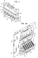
- the basic unit of the system is a modular connector block 11, as illustrated in Fig. 1.
- Block 11 which is preferably molded from a plastic material, such as a polycarbonate, has formed therein a plurality, such as six, eight pin connector jack openings 12,12 with their appropriate wiring and contacts incorporated therein.
- a name plate, identifying numbers as shown in Fig. 5
- the front face 14 of connector block 11 continues above the top of block 11 in the form of a flange 16 which has a central opening 17 therein.
- a cantilevered latch 18 which preferably. although not necessarily, is formed during the block molding or casting process. and, as will be apparent hereinafter, is used to lock connector block 11 in place in its panel, as best seen: for example, in Fig. 2.
- first and second pivot pins 22 and 23 are first and second pivot pins 22 and 23, the function of which will be explained more fully hereinafter.
- Each of the end surfaces 19 and 21 has a square notch or groove 24 and 26, respectively, extending across the end surfaces from the front face 14 of block 11 to the rear face 27 thereof.
- Each of slots 24 and 26 has a sloped portion 25 at the end thereof adjacent the front face of block 11.
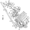
- FIG. 2A there is shown in perspective a portion of a panel 28 have a lower row of connector block receiving apertures 29,29 and an upper row of connector block receiving apertures 31,31.
- a connector block 11 is mounted in one of the apertures 31 and snapped into place by means of cantilevered latch 18.
- panel 28 has, extending from the rear surface 33 thereof, U-shaped connector block mounting brackets 34,34, positioned on each side of each aperture 29,29.
- Panel 28 and brackets 34 are preferably made of a suitable metallic material, such as steel or aluminum, and panel 28 has mounting holes 36,36 for mounting the panel of a rack, not shown.
- Fig. 2A there is shown in perspective a portion of a panel 28 have a lower row of connector block receiving apertures 29,29 and an upper row of connector block receiving apertures 31,31.
- a connector block 11 is mounted in one of the apertures 31 and snapped into place by means of cantilevered latch 18.
- panel 28 has, extending from the rear surface 33 thereof, U-shaped connector block mounting
- the upper connector block 11 is mounted in its operative position and held in place by means of latch 18 and pins 22 and 23 riding in U-shaped mounting brackets 34,34.
- the lower block 11 is shown in its wiring position, latch 18 having been released and block 11 pivoted on pins 22 and 23 in the direction of the arrow to the position shown, where the rear face 27 faces forward to provide access thereto for wiring the connector block 11.
- each connector block 11 Extending from the rear surface 27 of each connector block 11 are six columns 37,37 of slotted insulation displacement connectors (IDC's) 38,38, one column for each of the jack openings 12 and having eight IDC connectors 38,38 therein.
- IDC's insulation displacement connectors
- Each individual wire (not shown) leading from the cable to the connector block is inserted into an IDC 38 to wire each of the connector receptacles or openings 12.
- the slots of the IDC's 38,38 are oriented transversely to the block 11, parallel to the axes defined by the pivot pins, so that the individual wires can be laid flat on or adjacent to the rear surface 27, with each wire being bent to fit into its appropriate IDC.
- the openings 29,29 are provided with sloped lower corners 39,39, only the left ones of which can be seen clearly in Fig. 2A.
- the slopes 39,39 each engages shaped portion 25 of the slots 24 and 26 on block 11 and act as stops to prevent further rotation in the direction opposit to the direction of the arrow in Fig. 2B when the wires are being inserted into the IDC's, and the front face of panel 28 engages the slot 24 and 26 to prevent rotation in the direction of the arrow.
- the block 11 is effectively locked in place in the open position during the ???.
- it is lifted slightly to disengage the slots 24 and 26 from the panel and sloped portion 39, it is rotated back into its operative position and snapped into place by means of latch 18.
- connections or cross-connections can then be made among the various jack connectors in the manner shown, for example, in the Arnett patent in Fig. 1 thereof.
- Figs. 3, 4, and 5 there are shown the steps involved in wiring a connector block in a second preferred embodiment of the invention.
- a portion of the panel 28 is shown, as modified by first and second latch openings 41 and 42 formed in the upstanding webs 43,43 in the panel.
- Retainer clips 44,46 preferably formed of a suitable polycarbonate material, have latching members 47 and 48 formed on a rear surface thereof which are adapted to fit within the openings 42 and 41 respectively to latch the clip in place on the panel.
- the clip 44 is shown mounted in place, while the clip 46 is shown being mounted.
- the clip 46 is mounted by insertion of latch member 47 in opening 42 and rotation of the clip 46 in the direction of the shaded arrow until member 48 snaps into place in opening 41.
- the details of the configuration of retainer clips 44 and 46, which are identical, will be discussed more fully in connection with Figs. 6A, 6B, and 6C.
- the connector block 11 is placed on and supported by the retainer clips 44 and 46, with the flanges 16 resting upon a contoured flange 51 on each of the clips 44 and 46, and with the pivot pins 22 and 23 resting in semi-circular support portions 52 on each of the clips 44 and 46, and the rear face 27 of block 11 facing to the front, as shown in Fig. 4.
- the individual wires in each of the groups 50,50 are then dressed to length and inserted into their respective IDC's 38,38 as shown in Fig. 4.
- the individual wires may be placed alongside the column 37 and rest against or closely adjacent to rear surface 27. Such an arrangement is more orderly than would be the case if the IDC's were oriented parallel to the column 37.
- the block 11 is removed from the retainer clips 44 and 46 and rotated to bring the front surface 14 to the front and, with the pivot pins 22 and 23 riding in their respective mounting brackets 34, the block 11 is snapped into place and held there by means of latch 18, as shown in Fig. 5.
- brackets 34 Introduction of the pins 22 and 23 into brackets 34 is facilitated by notches 53 in the webs 43 which create an opening slightly wider than the transverse distance defined by the ends of the pins 22 and 23 so that they may pass therethrough and then drop down within the brackets 34 to rest thereon and to be prevented from slipping out by means of the un-notched retaining portion 54 of web 43.
- notches 53 in the webs 43 which create an opening slightly wider than the transverse distance defined by the ends of the pins 22 and 23 so that they may pass therethrough and then drop down within the brackets 34 to rest thereon and to be prevented from slipping out by means of the un-notched retaining portion 54 of web 43.
- FIG. 5 As shown in Fig. 5, after block 11 is in place, connections may be made thereto.
- Retainer clips 44 and 46 may be removed after the connector block is installed; however, when left in place, they function to support and maintain the cables 56 neatly adjacent the panel, thereby minimizing confusion, as shown in Fig. 5.
- Figs. 6A, 6B and 6C depict the configuration of the retainer clip 44.
- the clip 44 has the approximate shape of a frustrated triangle and comprises a base web 58, a rear support web 59, a sloping web 61, and a semi-circular pivot pin supporting member or bushing 52 joined to web 61 and to rear web 59 by means of a web 63.
- Web 61 has a slot 64 extending across it to allow cables 56 to pass through and to rest upon web 58, as shown in Fig. 5.
- the clip 44 is preferably molded from a suitable polycarbonate material, and has strengthening ribs 66 and 67 formed during the molding process to strengthen the webs 58, 59, and 63 as well as providing extra support for the semi-circular support bushing member 52.
- First and second semi-resilient latch clips 47 and 48 extend from the rear face of rear web 59, as best seen in Fig. 6B, and the rear face of web 59 also has stand-offs 71,71 formed thereon.
- a contoured flange 51 which is adapted to receive and to hold flange 16 of connector block 11 as shown by the dashed lines in Fig. 6B, while pivot pins 22 and 23 rest in the support bushings 52,52, also as best seen in Fig. 6B.
- clips 44 which is identical to clip 46 and the other clips, which are not shown, is attached by insertion of latch clip 47 into hole 42 in panel 28 and rotation of retainer clip 44 (or 46) to cause latch clip 48 to pass through hole 41 and to snap into place.
- the resiliency of clips 47 and 48, and the presence of stand-offs 71,71 insure that the retainer clip 44 is firmly held in place on panel 28, as best seen in Fig. 6B.
- Fig. 7A there is shown an arrangement for organizing the feeder cables located in the rear of the rack upon which the panels 28,28 are to be mounted.
- Panel 28 is formed with, or has attached thereto, a transverse flange member 72 to which are attached one ore more cable organizing brackets 73,73.
- Each bracket 73 has first and second legs 74 and 76 extending from cross piece 77 to form an approximately D-shaped bracket having a cable opening 78 for passage of a cable into the interior space of the D-shape.
- Extending from cross-piece 77 are first and second mounting flanges 79 and 81, as best seen in Fig.
- flange 72 has a notch 84 for receiving flange 81, which may be formed in flange 72, or which may be formed by means of a second interrupted flange member 86, as shown. It is to be understood that there is shown in Figs. 7A and 7B only one possible, albeit preferred, way of mounting the cable organizers 73,73, to the rear of panel 28. In addition, such organizers may have any of a number of different forms or shapes, that, shown in Figs. 7A and 7B, being by way of example only.
- Figs. 8A and 8B there is shown a modified connector block 11, wherein radiused ramps 87 and 88 extend from the front face 14 of block 11 on either side thereof.
- Ramps 87 and 88 are preferably formed when block 11 is molded or otherwise formed, and function to facilitate insertion of the block 11 into the opening 29 by acting as guides. For simplicity, the remaining details of block 11 have not been shown.
- the present invention constitutes a modular panel and connector arrangement that requires no mounting hardware, that permits access to the rear of the connectors from the front of the panel, that greatly increases both flexibility and diversity in making connections, and that affords both cable and wire management to reduce the level of confusion that obtains with unconfirmed wires and cables.
- the modular connector blocks can individually be wired, repaired, or the connections switched without disturbing the remaining connectors arrayed on the panel, or the panel itself.
Landscapes
- Physics & Mathematics (AREA)
- Engineering & Computer Science (AREA)
- Computer Networks & Wireless Communication (AREA)
- General Physics & Mathematics (AREA)
- Optics & Photonics (AREA)
- Details Of Connecting Devices For Male And Female Coupling (AREA)
- Connector Housings Or Holding Contact Members (AREA)
Applications Claiming Priority (2)
| Application Number | Priority Date | Filing Date | Title |
|---|---|---|---|
| US08/358,872 US5639261A (en) | 1994-12-23 | 1994-12-23 | Modular cross-connect system |
| US358872 | 1994-12-23 |
Publications (3)
| Publication Number | Publication Date |
|---|---|
| EP0718926A2 true EP0718926A2 (de) | 1996-06-26 |
| EP0718926A3 EP0718926A3 (de) | 1999-03-31 |
| EP0718926B1 EP0718926B1 (de) | 2002-09-11 |
Family
ID=23411390
Family Applications (1)
| Application Number | Title | Priority Date | Filing Date |
|---|---|---|---|
| EP95308831A Expired - Lifetime EP0718926B1 (de) | 1994-12-23 | 1995-12-06 | Modulares Kreuzschaltungssystem |
Country Status (10)
| Country | Link |
|---|---|
| US (1) | US5639261A (de) |
| EP (1) | EP0718926B1 (de) |
| JP (1) | JP3356604B2 (de) |
| KR (1) | KR100233970B1 (de) |
| CN (1) | CN1131830A (de) |
| AU (1) | AU699808B2 (de) |
| CA (1) | CA2162414C (de) |
| DE (1) | DE69528142T2 (de) |
| SG (1) | SG54983A1 (de) |
| TW (1) | TW346691B (de) |
Cited By (7)
| Publication number | Priority date | Publication date | Assignee | Title |
|---|---|---|---|---|
| WO1998005101A1 (en) * | 1996-07-29 | 1998-02-05 | The Whitaker Corporation | Communications outlet having termination aid platform |
| GB2316552A (en) * | 1996-08-21 | 1998-02-25 | Whitaker Corp | Fuse box and wiring harness assembly |
| EP0887893A3 (de) * | 1997-05-30 | 1999-11-17 | Lucent Technologies Inc. | Mehrstellungssteckdosenhalterung |
| EP1127286A1 (de) * | 1998-11-07 | 2001-08-29 | Tyco Electronics Raychem NV | Platte zum halten einer vielzahl von faseroptischen steckern |
| WO2003044902A1 (en) * | 2001-11-16 | 2003-05-30 | Adc Telecommunications, Inc. | Angled rj to rj patch panel |
| WO2008106127A1 (en) * | 2007-02-28 | 2008-09-04 | Corning Cable Systems Llc | Fiber optic drop terminals for multiple dwelling units |
| WO2014189721A1 (en) * | 2013-05-21 | 2014-11-27 | Corning Optical Communications LLC | Tiltable gang fiber adaptor assembly |
Families Citing this family (74)
| Publication number | Priority date | Publication date | Assignee | Title |
|---|---|---|---|---|
| JPH09115590A (ja) * | 1995-10-13 | 1997-05-02 | Yazaki Corp | コネクタ装置 |
| US5879197A (en) * | 1997-11-17 | 1999-03-09 | Adc Telecommunications, Inc. | Jack module |
| US6537106B1 (en) | 1998-06-05 | 2003-03-25 | Adc Telecommunications, Inc. | Telecommunications patch panel with angled connector modules |
| US6053764A (en) * | 1998-06-30 | 2000-04-25 | Lucent Technologies Inc. | Patch panel and interlocking module |
| US6146167A (en) * | 1998-09-16 | 2000-11-14 | Telect, Inc. | Telecommunication module having edge mounted jack and switch therefor |
| US6587354B1 (en) | 1998-09-18 | 2003-07-01 | Duane B. Kutsch | Telecommunication assembly |
| US6229691B1 (en) * | 1998-11-13 | 2001-05-08 | Hewlett-Packard Company | Apparatus and method for mounting a power distribution unit within an equipment enclosure |
| US6242698B1 (en) | 1998-12-08 | 2001-06-05 | Avaya Technology Corporation | Interchangeable adapter face plates |
| US6111195A (en) * | 1999-01-13 | 2000-08-29 | Steelcase Inc. | Communications cabinet and mounting system |
| US6334792B1 (en) | 1999-01-15 | 2002-01-01 | Adc Telecommunications, Inc. | Connector including reduced crosstalk spring insert |
| IL144210A0 (en) * | 1999-01-15 | 2002-05-23 | Adc Telecommunications Inc | Telecommunication jack assembly |
| US6118075A (en) * | 1999-02-17 | 2000-09-12 | Lucent Technologies Inc. | Stackable universal pitch cable trough system |
| US6168474B1 (en) | 1999-06-04 | 2001-01-02 | Lucent Technologies Inc. | Communications connector having crosstalk compensation |
| US6457984B1 (en) | 1999-09-21 | 2002-10-01 | La Mont, Llc | Electrical jackbox apparatus and method |
| US6460951B1 (en) * | 1999-12-20 | 2002-10-08 | Hubbell Incorporated | Telecommunications enclosure box employing mounting brackets for supporting components providing communicative connection of remote multimedia equipment |
| US6872006B2 (en) * | 2000-03-03 | 2005-03-29 | Virginia Panel Corporation | Fiber optic cable assembly |
| US6786647B1 (en) * | 2001-03-16 | 2004-09-07 | Nortel Networks Limited | Mechanically constrained connection |
| US6435904B1 (en) | 2001-06-01 | 2002-08-20 | Fellowes, Inc. | Multiple peripheral connection device for connecting multiple peripheral devices to a host device |
| US6600106B2 (en) * | 2001-07-11 | 2003-07-29 | Adc Telecommunications, Inc. | Cable management bar and patch panel |
| US6504726B1 (en) * | 2001-11-16 | 2003-01-07 | Adc Telecommunications, Inc. | Telecommunications patch panel |
| US6695649B1 (en) | 2002-08-05 | 2004-02-24 | Panduit Corp | Vertical PCB jack with shield |
| US20050026506A1 (en) * | 2002-11-18 | 2005-02-03 | Trompeter Electronics, Inc. | Modular cross-connect with hot-swappable modules |
| US6752665B2 (en) * | 2002-11-18 | 2004-06-22 | Trompeter Electronics, Inc. | Modular cross-connect with removable switch assembly |
| US6814624B2 (en) * | 2002-11-22 | 2004-11-09 | Adc Telecommunications, Inc. | Telecommunications jack assembly |
| US20040209515A1 (en) * | 2003-04-03 | 2004-10-21 | Caveney Jack E. | High density patch panel |
| US7094091B2 (en) * | 2003-10-27 | 2006-08-22 | Molex Incorporated | Swivel adapter |
| US20050151023A1 (en) * | 2003-12-16 | 2005-07-14 | Ribbe David J. | Control system for model aircraft |
| AU158235S (en) | 2004-06-16 | 2005-08-03 | Krone Australia Holdings Pty Ltd | Patch panel |
| US7526171B2 (en) * | 2004-07-22 | 2009-04-28 | Panduit Corp. | Front access punch down patch panel |
| US20060067068A1 (en) * | 2004-09-27 | 2006-03-30 | Petersen Cyle D | Digital cross-connect system and rack arrangement |
| US7091418B1 (en) | 2005-04-01 | 2006-08-15 | Adc Telecommunications, Inc. | Cable management bar and patch panel |
| EP1808878B1 (de) * | 2006-01-11 | 2008-08-20 | Siemens Aktiengesellschaft | Elektrische Einrichtung mit Ausschaltung des Laststromkreises in explosionsgefährdeter Umgebung |
| US7393249B2 (en) * | 2006-04-21 | 2008-07-01 | Trompeter Electronics, Inc. | Interconnection and monitoring module |
| US20070257160A1 (en) * | 2006-05-08 | 2007-11-08 | M/A-Com, Inc. | Cable attaching clamp |
| US7357667B2 (en) * | 2006-06-22 | 2008-04-15 | Adc Telecommunications, Inc. | Telecommunications patch |
| US7343078B2 (en) | 2006-06-29 | 2008-03-11 | Commscope Solutions Properties, Llc | Patch panels with communications connectors that are rotatable about a vertical axis |
| US7715208B2 (en) * | 2006-09-08 | 2010-05-11 | Intel Corporation | Configurable multi-faceted input/output panel |
| US7722402B2 (en) * | 2006-10-16 | 2010-05-25 | Tyco Electronics Corporation | Panel interface module which provides electrical connectivity between panel and shielded jacks |
| US7488205B2 (en) * | 2006-12-13 | 2009-02-10 | Commscope, Inc. Of North Carolina | Fixed angled patch panel |
| EP2137794B1 (de) * | 2007-03-29 | 2018-03-07 | The Siemon Company | Modularer verbinder mit verringerter abschlussvariabilität und verbesserter leistungsfähigkeit |
| WO2009018668A1 (en) * | 2007-08-09 | 2009-02-12 | Belden Cdt Canada Inc. | Telescoping connector assembly |
| SG150428A1 (en) | 2007-09-06 | 2009-03-30 | Adc Gmbh | Telecommunications patch panel |
| US20090163043A1 (en) * | 2007-12-21 | 2009-06-25 | Yannick Demers | Patch panel with angled module |
| US8130502B2 (en) * | 2008-02-15 | 2012-03-06 | Panduit Corp. | Modular stackable angled patch panel for enclosure |
| US20090257174A1 (en) * | 2008-04-15 | 2009-10-15 | Mahesh Jaywant Rane | Self-disengaging contacts for secondary circuits of draw-out type circuit breakers |
| DE102009010940B4 (de) | 2008-08-16 | 2018-05-17 | Drägerwerk AG & Co. KGaA | Vorrichtung zur Versorgung von medizinischen Geräten mit Gas oder elektrischer Energie |
| US8290330B2 (en) * | 2008-09-05 | 2012-10-16 | Adc Gmbh | Patch panel assembly |
| US7909622B2 (en) | 2009-02-27 | 2011-03-22 | Tyco Electronics Corporation | Shielded cassette for a cable interconnect system |
| US20100221955A1 (en) * | 2009-02-27 | 2010-09-02 | Tyco Electronics Corporation | Cassette having interchangable rear mating connectors |
| US7909643B2 (en) * | 2009-02-27 | 2011-03-22 | Tyco Electronics Corporation | Cassette for a cable interconnect system |
| US7909619B2 (en) * | 2009-02-27 | 2011-03-22 | Tyco Electronics Corporation | Cassette with locking feature |
| US7878824B2 (en) * | 2009-02-27 | 2011-02-01 | Tyco Electronics Corporation | Shielded cassette for a cable interconnect system |
| US7874869B2 (en) * | 2009-03-26 | 2011-01-25 | Cisco Technology, Inc. | Reconfigurable patch panel |
| US7922522B2 (en) * | 2009-04-02 | 2011-04-12 | Fluke Corporation | Instrument having oblique mounted terminal posts |
| US8744228B2 (en) * | 2009-05-22 | 2014-06-03 | Commscope, Inc. Of North Carolina | Telecommunications patching system with cable management system and related cable management equipment |
| US8760875B2 (en) * | 2009-11-24 | 2014-06-24 | Telect, Inc. | High density digital signal cross-connect system |
| US8096833B2 (en) * | 2010-01-15 | 2012-01-17 | Tyco Electronics Corporation | Plug assembly |
| US8062049B2 (en) | 2010-01-15 | 2011-11-22 | Tyco Electronics Corporation | Latch assembly for a connector assembly |
| US9042699B2 (en) * | 2010-06-02 | 2015-05-26 | Tyco Electronics Corporation | Switch rack system |
| US8337238B2 (en) | 2010-07-19 | 2012-12-25 | Tyco Electronics Corporation | Cable clip for a connector assembly |
| DE102010041874B4 (de) * | 2010-10-01 | 2020-06-18 | Te Connectivity Germany Gmbh | Optischer Substrat-Schwenkverbinder, optischer Substrat-Gegenverbinder, optische Substrat-Verbindungseinrichtung, konfektioniertes Lichtwellenleiter-Kabel sowie elektrisches Gerät |
| EP2456017B1 (de) * | 2010-11-18 | 2014-06-04 | Siemens Aktiengesellschaft | Steckervorrichtung für elektronische Baugruppen in Automatisierungssystemen |
| KR101186628B1 (ko) * | 2011-05-04 | 2012-09-27 | 주식회사 경신 | 차량용 배터리모듈의 전압센싱모듈 |
| WO2013183011A2 (en) * | 2012-06-07 | 2013-12-12 | Intal Tech Ltd. | Electronic equipment building blocks for rack mounting |
| KR20130143339A (ko) * | 2012-06-21 | 2013-12-31 | 삼성전자주식회사 | 각도조절 이어잭 모듈 |
| CN104283083B (zh) * | 2013-07-05 | 2016-04-06 | 好庆科技企业股份有限公司 | 连接器旋转框、连接器及连接器基板装置 |
| US9885845B2 (en) * | 2015-01-15 | 2018-02-06 | Commscope, Inc. Of North Carolina | Module and assembly for fiber optic interconnections |
| CN104617456B (zh) * | 2015-02-13 | 2017-03-22 | 南车株洲电力机车有限公司 | 一种车端连接器悬挂支架 |
| US9832904B1 (en) * | 2016-03-28 | 2017-11-28 | Amazon Technologies, Inc. | Patch panel assembly |
| DE102017113124A1 (de) * | 2017-06-14 | 2018-12-20 | Abb Schweiz Ag | Verbindungsvorrichtung für Verlegekabel und Netzwerkkabel |
| US10222562B1 (en) * | 2017-09-07 | 2019-03-05 | Quanta Computer Inc. | Flexible connector interface |
| DE102018115588B4 (de) * | 2018-06-28 | 2021-02-11 | Phoenix Contact Gmbh & Co. Kg | Haltevorrichtung für eine Rangierwabe und Rangierwabe |
| US12272898B2 (en) * | 2019-08-14 | 2025-04-08 | Commscope Technologies Llc | Telecommunications patch panel with angled connector modules |
| KR102348788B1 (ko) * | 2021-02-18 | 2022-01-07 | (주)도원엔지니어링건축사사무소 | 공동주택 통신실에 설치되는 초고속 정보통신 광분배함 |
Citations (3)
| Publication number | Priority date | Publication date | Assignee | Title |
|---|---|---|---|---|
| US4536052A (en) | 1984-02-09 | 1985-08-20 | At&T Information Systems | Modular cross-connect panel |
| US5238426A (en) | 1992-06-11 | 1993-08-24 | At&T Bell Laboratories | Universal patch panel for communications use in buildings |
| US5302140A (en) | 1993-04-02 | 1994-04-12 | At&T Bell Laboratories | Connector with mounting collar for use in universal patch panel systems |
Family Cites Families (10)
| Publication number | Priority date | Publication date | Assignee | Title |
|---|---|---|---|---|
| US3904936A (en) * | 1974-03-14 | 1975-09-09 | Cook Electric Co | Rotating terminal block assembly |
| US3992070A (en) * | 1975-05-15 | 1976-11-16 | International Harvester Company | Lockable flip-up instrument panel |
| US4099823A (en) * | 1977-03-18 | 1978-07-11 | Bell Telephone Laboratories, Incorporated | High density multipair cable connecting block |
| US4712232A (en) * | 1986-03-14 | 1987-12-08 | Armor Metals, Inc. | Multiple telephone jack slide assembly |
| FR2635922B1 (fr) * | 1988-08-24 | 1990-10-12 | Alsthom Cgee | Auxiliaire de raccordement pour prise fixe de connexion electrique |
| CH677425A5 (en) * | 1989-04-06 | 1991-05-15 | Reichle & De Massari Fa | Modular wall plug socket for low current appts. components - has multi-pin plug element fitted into variable window in pivoted front cover |
| US5122069A (en) * | 1989-07-28 | 1992-06-16 | Amp Incorporated | Access flooring module |
| US5090645A (en) * | 1990-08-31 | 1992-02-25 | Minnesota Mining And Manufacturing Company | Cable stacking member |
| DE4108446C1 (de) * | 1991-03-15 | 1992-04-30 | Abb Patent Gmbh, 6800 Mannheim, De | |
| DE9113002U1 (de) * | 1991-10-18 | 1992-05-27 | Moll, Hans, 7996 Meckenbeuren | Rahmen für Steckverbindungen von Datenleitungen |
-
1994
- 1994-12-23 US US08/358,872 patent/US5639261A/en not_active Expired - Lifetime
-
1995
- 1995-01-19 TW TW084100461A patent/TW346691B/zh not_active IP Right Cessation
- 1995-11-08 CA CA002162414A patent/CA2162414C/en not_active Expired - Lifetime
- 1995-12-06 EP EP95308831A patent/EP0718926B1/de not_active Expired - Lifetime
- 1995-12-06 DE DE69528142T patent/DE69528142T2/de not_active Expired - Lifetime
- 1995-12-20 CN CN95120892A patent/CN1131830A/zh active Pending
- 1995-12-20 AU AU40567/95A patent/AU699808B2/en not_active Expired
- 1995-12-22 JP JP33454795A patent/JP3356604B2/ja not_active Expired - Fee Related
- 1995-12-22 KR KR1019950054929A patent/KR100233970B1/ko not_active Expired - Fee Related
- 1995-12-22 SG SG1995002307A patent/SG54983A1/en unknown
Patent Citations (3)
| Publication number | Priority date | Publication date | Assignee | Title |
|---|---|---|---|---|
| US4536052A (en) | 1984-02-09 | 1985-08-20 | At&T Information Systems | Modular cross-connect panel |
| US5238426A (en) | 1992-06-11 | 1993-08-24 | At&T Bell Laboratories | Universal patch panel for communications use in buildings |
| US5302140A (en) | 1993-04-02 | 1994-04-12 | At&T Bell Laboratories | Connector with mounting collar for use in universal patch panel systems |
Cited By (16)
| Publication number | Priority date | Publication date | Assignee | Title |
|---|---|---|---|---|
| WO1998005101A1 (en) * | 1996-07-29 | 1998-02-05 | The Whitaker Corporation | Communications outlet having termination aid platform |
| US5741158A (en) * | 1996-07-29 | 1998-04-21 | The Whitaker Corporation | Communications outlet having termination aid platform |
| GB2316552A (en) * | 1996-08-21 | 1998-02-25 | Whitaker Corp | Fuse box and wiring harness assembly |
| EP0887893A3 (de) * | 1997-05-30 | 1999-11-17 | Lucent Technologies Inc. | Mehrstellungssteckdosenhalterung |
| EP1127286A1 (de) * | 1998-11-07 | 2001-08-29 | Tyco Electronics Raychem NV | Platte zum halten einer vielzahl von faseroptischen steckern |
| GB2397703A (en) * | 2001-11-16 | 2004-07-28 | Adc Telecommunications Inc | Angled rj to rj patch panel |
| US6736670B2 (en) | 2001-11-16 | 2004-05-18 | Adc Telecommunications, Inc. | Angled RJ to RJ patch panel |
| US6761585B2 (en) | 2001-11-16 | 2004-07-13 | Adc Telecommunications, Inc. | Angled RJ to RJ patch panel |
| WO2003044902A1 (en) * | 2001-11-16 | 2003-05-30 | Adc Telecommunications, Inc. | Angled rj to rj patch panel |
| GB2397703B (en) * | 2001-11-16 | 2006-05-31 | Adc Telecommunications Inc | Patch panel |
| US7066771B2 (en) | 2001-11-16 | 2006-06-27 | Adc Telecommunications, Inc. | Angled RJ to RJ patch panel |
| US7241182B2 (en) | 2001-11-16 | 2007-07-10 | Adc Telecommunications, Inc. | Angled RJ to RJ patch panel |
| US7686658B2 (en) | 2001-11-16 | 2010-03-30 | Adc Telecommunications, Inc. | Angled RJ to RJ patch panel |
| WO2008106127A1 (en) * | 2007-02-28 | 2008-09-04 | Corning Cable Systems Llc | Fiber optic drop terminals for multiple dwelling units |
| US7499622B2 (en) | 2007-02-28 | 2009-03-03 | Corning Cable Systems Llc | Fiber optic drop terminals for multiple dwelling units |
| WO2014189721A1 (en) * | 2013-05-21 | 2014-11-27 | Corning Optical Communications LLC | Tiltable gang fiber adaptor assembly |
Also Published As
| Publication number | Publication date |
|---|---|
| KR100233970B1 (ko) | 1999-12-15 |
| EP0718926A3 (de) | 1999-03-31 |
| KR960027073A (ko) | 1996-07-22 |
| CA2162414A1 (en) | 1996-06-24 |
| JP3356604B2 (ja) | 2002-12-16 |
| DE69528142T2 (de) | 2003-07-31 |
| CN1131830A (zh) | 1996-09-25 |
| CA2162414C (en) | 1999-08-31 |
| DE69528142D1 (de) | 2002-10-17 |
| US5639261A (en) | 1997-06-17 |
| EP0718926B1 (de) | 2002-09-11 |
| AU699808B2 (en) | 1998-12-17 |
| JPH08236191A (ja) | 1996-09-13 |
| TW346691B (en) | 1998-12-01 |
| AU4056795A (en) | 1996-07-04 |
| SG54983A1 (en) | 1998-12-21 |
Similar Documents
| Publication | Publication Date | Title |
|---|---|---|
| CA2162414C (en) | Modular cross-connect system | |
| US6053764A (en) | Patch panel and interlocking module | |
| EP2078426B1 (de) | Aufrüstbares patchpanel | |
| US7979985B2 (en) | Multi-port mounting bracket and method | |
| US9705250B2 (en) | Patch cord plug organizer | |
| US6614978B1 (en) | Slack cable management system | |
| US5396405A (en) | Wiring cabinet having vertically aligned patch panels | |
| US4536052A (en) | Modular cross-connect panel | |
| US5741158A (en) | Communications outlet having termination aid platform | |
| US5148353A (en) | Mounting system for installation of communication boxes having a convex bottom post and a rigid top post | |
| CN111345046B (zh) | 具有接地线的电信板 | |
| CN101480062A (zh) | 具有可绕垂直轴线转动的通信接头的转插板 | |
| KR100530429B1 (ko) | 전기통신네트워크에서사용하는개선된인터페이스카드 | |
| NZ543702A (en) | Modular wiring system for data connection using male and female compound connectors with at least two jacks on each connector | |
| US6676430B1 (en) | Board mounted jack module | |
| US6358080B1 (en) | Snap-in module system | |
| US6332795B1 (en) | Hinged connection system | |
| HK1003760A (en) | Modular cross-connect system | |
| GB2351854A (en) | Ditribution cable module | |
| CN111615283A (zh) | 用于电信设备的缆线管理环和面板 |
Legal Events
| Date | Code | Title | Description |
|---|---|---|---|
| PUAI | Public reference made under article 153(3) epc to a published international application that has entered the european phase |
Free format text: ORIGINAL CODE: 0009012 |
|
| AK | Designated contracting states |
Kind code of ref document: A2 Designated state(s): DE GB SE |
|
| PUAL | Search report despatched |
Free format text: ORIGINAL CODE: 0009013 |
|
| AK | Designated contracting states |
Kind code of ref document: A3 Designated state(s): DE GB SE |
|
| 17P | Request for examination filed |
Effective date: 19990916 |
|
| 17Q | First examination report despatched |
Effective date: 20000314 |
|
| GRAG | Despatch of communication of intention to grant |
Free format text: ORIGINAL CODE: EPIDOS AGRA |
|
| GRAG | Despatch of communication of intention to grant |
Free format text: ORIGINAL CODE: EPIDOS AGRA |
|
| GRAH | Despatch of communication of intention to grant a patent |
Free format text: ORIGINAL CODE: EPIDOS IGRA |
|
| GRAH | Despatch of communication of intention to grant a patent |
Free format text: ORIGINAL CODE: EPIDOS IGRA |
|
| GRAA | (expected) grant |
Free format text: ORIGINAL CODE: 0009210 |
|
| AK | Designated contracting states |
Kind code of ref document: B1 Designated state(s): DE GB SE |
|
| REG | Reference to a national code |
Ref country code: GB Ref legal event code: FG4D |
|
| REF | Corresponds to: |
Ref document number: 69528142 Country of ref document: DE Date of ref document: 20021017 |
|
| PLBE | No opposition filed within time limit |
Free format text: ORIGINAL CODE: 0009261 |
|
| STAA | Information on the status of an ep patent application or granted ep patent |
Free format text: STATUS: NO OPPOSITION FILED WITHIN TIME LIMIT |
|
| 26N | No opposition filed |
Effective date: 20030612 |
|
| REG | Reference to a national code |
Ref country code: HK Ref legal event code: WD Ref document number: 1003760 Country of ref document: HK |
|
| PGFP | Annual fee paid to national office [announced via postgrant information from national office to epo] |
Ref country code: DE Payment date: 20091230 Year of fee payment: 15 |
|
| PGFP | Annual fee paid to national office [announced via postgrant information from national office to epo] |
Ref country code: SE Payment date: 20091230 Year of fee payment: 15 |
|
| REG | Reference to a national code |
Ref country code: SE Ref legal event code: EUG |
|
| PG25 | Lapsed in a contracting state [announced via postgrant information from national office to epo] |
Ref country code: SE Free format text: LAPSE BECAUSE OF NON-PAYMENT OF DUE FEES Effective date: 20101207 |
|
| REG | Reference to a national code |
Ref country code: DE Ref legal event code: R119 Ref document number: 69528142 Country of ref document: DE Effective date: 20110701 |
|
| PG25 | Lapsed in a contracting state [announced via postgrant information from national office to epo] |
Ref country code: DE Free format text: LAPSE BECAUSE OF NON-PAYMENT OF DUE FEES Effective date: 20110701 |
|
| PGFP | Annual fee paid to national office [announced via postgrant information from national office to epo] |
Ref country code: GB Payment date: 20141229 Year of fee payment: 20 |
|
| REG | Reference to a national code |
Ref country code: GB Ref legal event code: PE20 Expiry date: 20151205 |
|
| PG25 | Lapsed in a contracting state [announced via postgrant information from national office to epo] |
Ref country code: GB Free format text: LAPSE BECAUSE OF EXPIRATION OF PROTECTION Effective date: 20151205 |