EP0718933B1 - Lampenfassung - Google Patents
Lampenfassung Download PDFInfo
- Publication number
- EP0718933B1 EP0718933B1 EP95308266A EP95308266A EP0718933B1 EP 0718933 B1 EP0718933 B1 EP 0718933B1 EP 95308266 A EP95308266 A EP 95308266A EP 95308266 A EP95308266 A EP 95308266A EP 0718933 B1 EP0718933 B1 EP 0718933B1
- Authority
- EP
- European Patent Office
- Prior art keywords
- bulb
- contact piece
- base
- side contact
- receiving portion
- Prior art date
- Legal status (The legal status is an assumption and is not a legal conclusion. Google has not performed a legal analysis and makes no representation as to the accuracy of the status listed.)
- Expired - Lifetime
Links
Images




Classifications
-
- H—ELECTRICITY
- H01—ELECTRIC ELEMENTS
- H01R—ELECTRICALLY-CONDUCTIVE CONNECTIONS; STRUCTURAL ASSOCIATIONS OF A PLURALITY OF MUTUALLY-INSULATED ELECTRICAL CONNECTING ELEMENTS; COUPLING DEVICES; CURRENT COLLECTORS
- H01R33/00—Coupling devices specially adapted for supporting apparatus and having one part acting as a holder providing support and electrical connection via a counterpart which is structurally associated with the apparatus, e.g. lamp holders; Separate parts thereof
- H01R33/90—Coupling devices specially adapted for supporting apparatus and having one part acting as a holder providing support and electrical connection via a counterpart which is structurally associated with the apparatus, e.g. lamp holders; Separate parts thereof adapted for co-operation with two or more dissimilar counterparts
-
- H—ELECTRICITY
- H01—ELECTRIC ELEMENTS
- H01R—ELECTRICALLY-CONDUCTIVE CONNECTIONS; STRUCTURAL ASSOCIATIONS OF A PLURALITY OF MUTUALLY-INSULATED ELECTRICAL CONNECTING ELEMENTS; COUPLING DEVICES; CURRENT COLLECTORS
- H01R33/00—Coupling devices specially adapted for supporting apparatus and having one part acting as a holder providing support and electrical connection via a counterpart which is structurally associated with the apparatus, e.g. lamp holders; Separate parts thereof
- H01R33/05—Two-pole devices
- H01R33/06—Two-pole devices with two current-carrying pins, blades or analogous contacts, having their axes parallel to each other
- H01R33/09—Two-pole devices with two current-carrying pins, blades or analogous contacts, having their axes parallel to each other for baseless lamp bulb
-
- H—ELECTRICITY
- H01—ELECTRIC ELEMENTS
- H01R—ELECTRICALLY-CONDUCTIVE CONNECTIONS; STRUCTURAL ASSOCIATIONS OF A PLURALITY OF MUTUALLY-INSULATED ELECTRICAL CONNECTING ELEMENTS; COUPLING DEVICES; CURRENT COLLECTORS
- H01R33/00—Coupling devices specially adapted for supporting apparatus and having one part acting as a holder providing support and electrical connection via a counterpart which is structurally associated with the apparatus, e.g. lamp holders; Separate parts thereof
- H01R33/05—Two-pole devices
- H01R33/46—Two-pole devices for bayonet type base
Definitions
- This invention relates to a bulb socket assembly which can receive both a round base bulb and a wedge base bulb.
- the round base bulb includes a glass bulb body which accommodates a filament, a round base attached to a lower end of the bulb body, and positive and negative contacts provided on an end face and a peripheral face of the base.
- the wedge base bulb includes a glass bulb body which accommodates a filament, a flat base attached to a lower end of the bulb body, a pair of lead wires which are connected to the opposite ends of the filament and drawn out of a lower end of the base, and positive and negative contacts which are formed by turning an end of each lead wire onto a side face of the base so that the respective ends are disposed on opposite sides. These bulbs are inserted into the respective bulb receiving holes so that the respective contacts of the bulbs contact with the respective contact pieces mounted in the respective holes.
- the round base bulb is different from the wedge base bulb with respect to a configuration of a base to be inserted into the bulb, a configuration and an arrangement of contacts on the base and a configuration of contact pieces to be contacted with the contacts, configurations of the bulb sockets to receive the bulbs and contact pieces are naturally different from each other.
- a bulb socket for round base bulbs is known from EP-A- 518 671 and a bulb socket for wedge base bulbs is known from US-A-4 902 251.
- An object of the present invention is to provide a bulb socket which can receive both a round base bulb and a wedge base bulb.
- the present invention provides a bulb socket assembly comprising a socket body, a first pair of positive and negative contact pieces for a round base bulb, and a second pair of positive and negative contact pieces for a wedge base bulb, said socket body being provided in an end thereof with:
- a positive side contact piece out of a pair of positive side and negative side contact pieces for the round base bulb includes an L-shaped body in plan view, an S-shaped contact part which is provided on an upper face of one leg of the body and adapted to resiliently contact with a positive side contact on the base of the round base bulb, and a tab which extends downwardly from the other leg of the body.
- the contact piece is formed from a sheet of metal together with each part by press working.
- the body is provided on one leg thereof with an engaging piece formed by cutting and bending and one the other leg thereof with a short fitting part which extends perpendicularly to the other leg.
- the negative side contact piece includes an L-shaped body in plan view and a tab which is provided on one leg to extend downwardly.
- the contact piece is formed of a sheet of metal together with each part by a press work.
- the body is provided on an upper face of the other leg thereof with a tall fitting part which extends perpendicularly to the other leg.
- the fitting part is provided on an upper side with a tongue-like connection part which is cut and bent up inwardly to resiliently contact with a peripheral face of a negative side contact on the base of the round base bulb.
- the body is also provided with an engaging piece.
- a pair of positive side and negative side contact pieces for the wedge base bulb are of the same configuration in both positive and negative sides.
- Each contact piece includes an L-shaped body in plan view, a tab which is provided on one leg of the body to project downwardly, and a tall fitting part which is provided on an upper face of the other leg of the body perpendicularly.
- the body is provided on an upper face of a bent portion of the body with a tall stopper and a short connection piece which are juxtaposed on the upper face.
- the contact piece is formed of a sheet of metal together with each part.
- a positive side contact piece holder out of the pair of positive side and negative side contact piece holders is formed into a positive side contact piece insertion groove adapted to receive the positive side contact piece which is provided in a thicker wall with an introducing passage which extends axially from the open edge of the bulb receiving portion to the bottom face to receive the fitting part of the contact piece and is provided with a narrow channel which is opened in an interior of the bulb receiving portion to pass a proximal end of the body through a lateral center part of the introducing passage.
- the bulb receiving portion is provided in the bottom face with an introducing slot which is communicated with the channel to receive the body and is also provided in the bottom face with a through-hole which is adapted to pass the tab.
- the negative side contact piece holder is formed into the negative side contact piece insertion groove adapted to receive the negative side contact piece which is provided in the thicker wall with an introducing passage which extends axially from the open edge of the bulb receiving portion to the bottom face to receive the fitting part of the contact piece and is provided with a wide channel which is opened in an interior of the bulb receiving portion from the lateral center part of the passage.
- the channel permits a proximal end of the body to pass therethrough and a tongue-like connection part to project inwardly therethrough.
- the bulb receiving portion is provided in the bottom face with an introducing slot which is communicated with the channel and is also provided with a through-hole which is adapted to pass the tab.
- a pair of positive and negative contact pieces for the round base bulb and a pair of positive and negative contact pieces are received in the common contact piece holder in the bulb receiving hole.
- the common bulb socket for the round base bulb and the wedge base bulb is provided in accordance with the present invention, the number of parts is reduced and the cost is greatly lowered.
- the contact piece holders are made common, the structure of the bulb socket is simplified and the production cost is lowered.
- FIGS. 1 through 21 An embodiment of a bulb socket in accordance with the present invention will be described below by referring now to FIGS. 1 through 21.
- a round base bulb 1 as shown in FIG. 3, includes a bulb body 2 accommodating a filament, a round base 3 mounted on a lower end of the bulb body 2, a positive side contact 4 mounted on an end face of the base 3, and a negative side contact formed on an outer peripheral face of the base 5.
- the base 3 is provided on its outer peripheral end face with a pair of projections 6 which are spaced circumferentially at an angle of 180° to be engaged with a bulb socket 21.
- a wedge base bulb 11 is shown in FIGS. 12 and 13.
- the wedge base bulb 11 includes a bulb body 12 accommodating a filament 14 and a flat base 13 united with a lower end of the bulb body 12.
- a width of the base 13 is the same distance as that between the projections 6 on the base 3 of the round base bulb 1.
- the opposite ends of the base 13 are adapted to enter into guide parts 27 in bulb insertion grooves 26 in the bulb socket 21 described hereinafter.
- the base 13 is provided on its opposite side faces with first projections 15 which serve to prevent the bulb 11 from coming out of the socket 21.
- Each projection 15 is disposed on a central portion of each side face of the base 13 symmetrically with respect to the center of the base 13 (see FIG. 19).
- Second projections 16 and third projections 17 are disposed adjacent to the opposite ends of the base 13 on each side face of the base 13 symmetrically with respect to the center of the base 13.
- the second projection 16 is disposed in the substantially same position as that of the first projection 15 at a height from the lower end of the base 13.
- the third projection 17 is disposed in a lower position than the first projection 15 at the height.
- a pair of lead wires which are connected to the opposite ends of the filament 14 are drawn from the lower end of the base 13 in a form of a loop and are turned up on the respective side faces of the base 13 so that a distal end of each lead wire is disposed between the first projection 15 and the second projection 16.
- the turned-up lead wires serve as positive and negative contacts 18, 18, respectively.
- the third projections 17, as shown in FIG. 19, together with the second projection 16 contact closely with the interior in a bulb receiving portion 23 to eliminate any plays between the base 13 and the socket 21 in a width direction of the base.
- the bulb socket 21 includes a socket body 22 made of a synthetic resin material. As shown in FIGS. 1 to 3, the bulb socket 21 is provided on its one end with the cylindrical bulb receiving portion 23 and on its other end with a rectangular male connector portion 24 adapted to couple to a female connector not shown.
- the bulb receiving portion 23 is provided in its interior with a pair of bulb insertion grooves 26, 26 which are spaced circumferentially at an angle of 180°.
- the bulb insertion groove 26, which is a so-called J-slot, serves to receive and engage with the round base bulb 1 in itself.
- the bulb insertion grooves 26 in this embodiment can receive the wedge base bulb 11. More particularly, as shown in FIG. 4, the bulb insertion groove 26 is provided with a guide part 27 which extends axially from an open end edge to a middle part.
- An engaging part 28 extends circumferentially to a clockwise direction in FIG. 1 from a lower end of the groove 26.
- the engaging part 28 is provided on its inner part with a recess 29 formed toward the open end edge of the bulb receiving portion 23.
- the opposite ends of the base 13 of the wedge base bulb 11 are firmly fitted in the guide parts 27 in the bulb insertion grooves 26.
- the round base bulb 1 is secured to the bulb receiving portion 23. Then, the projections 6 are fitted in the recesses 29 by an elastic force exerted in connection part 33 of a positive side contact piece 31 for the round base bulb 1, thereby preventing the projections 6 from turning back to the guide parts 27.
- the wedge base bulb 11 can be secured to the bulb receiving portion 23 when the opposite ends of the base 11 are inserted into the guide parts 27.
- the bulb socket 21 is provided symmetrically in its interior with a pair of contact piece insertion grooves 30a and 30b which are shifted circumferentially from the bulb insertion grooves 26, 26.
- the contact piece insertion groove 30a receives positive side contact piece 31 for the round base bulb 1 while the groove 30b receives a negative side contact piece 41 for the bulb 1.
- the respective contact piece insertion grooves 30a and 30b can receive contact pieces 61 for the wedge base bulb 11 (see FIGS. 12 and 14).
- the bulb socket 21 is formed into a thicker wall, which is bulged outwardly, at the portion in which the grooves 30a and 30b are provided.
- the positive side contact piece 31 for the round base bulb 1 is shown in FIGS. 6 to 8.
- the contact piece 31 includes an L-shaped body 32 in plan view, an S-shaped contact part 33 which is provided on an upper face of one leg of the body 32 and adapted to resiliently contact with a positive side contact 4 on the base of the round base bulb 1, and a tab 34 which extends downwardly from the other leg of the body 32.
- the contact piece is formed from a sheet of metal together with each part by press working.
- the body 32 is provided on one leg thereof with an engaging piece 35 formed by cutting and bending and on the other leg thereof with a short fitting part 36 which extends perpendicularly to the other leg.
- the positive side contact piece insertion groove 30a adapted to receive the positive side contact piece 31, as shown in FIG. 1, is provided in a thicker wall 39 with an introducing passage 50a which extends axially from the open edge of the bulb receiving portion 23 to the bottom face to receive the fitting part 36 of the contact piece 31 and is provided with a narrow channel 51a which is opened in an interior of the bulb receiving portion 23 to pass a proximal end of the body 32 through a lateral center part of the introducing passage 50a.
- the bulb receiving portion 23 is provided in the bottom face with an introducing slot 52a which is communicated with the channel 51a to receive the body 32 and is also provided in the bottom face with a through-hole 53a which is adapted to pass the tab 34.
- the fitting part 36 of the positive side contact piece 31 When the fitting part 36 of the positive side contact piece 31 is fitted in the introducing passage 50a in the contact piece insertion groove 30a and is pushed down to the lower end of the passage 50a, the body 32 enters into the introducing slot 52a in the lower end face of the bulb receiving portion 23 through the channel 51a.
- the engaging piece 35 fits in an engaging hole 54a in the slot 52a, the contact piece 31 is secured to the groove 30a.
- the S-shaped contact part 33 is disposed near the lower end of the bulb receiving portion 23, as shown in FIG. 3, and the tab 34 extends through the through-hole 53a along a side face of a partition 24a in a male connector portion 24.
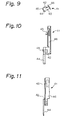
- a negative side contact piece 41 is shown in FIGS. 9 to 11.
- the negative side contact piece 41 includes an L-shaped body 42 in plan view and a tab 44 which is provided on one leg to extend downwardly.
- the contact piece 41 is formed from a sheet of metal together with each part by press working.
- the body 42 is provided on an upper face of the other leg thereof with a tall fitting part 46 which extends perpendicularly to the other leg.
- the fitting part 46 is provided on an upper side with a tongue-like connection part 43 which is cut and bent up inwardly to resiliently contact with a peripheral face of a negative side contact 5 on the base 3 of the round base bulb 1.
- the body 42 is also provided with an engaging piece 45.
- the negative side contact piece insertion groove 30b adapted to receive the negative side contact piece 41 as shown in FIG. 1, is provided in the thicker wall with an introducing passage 50b which extends axially from the open edge of the bulb receiving portion 23 to the bottom face to receive the fitting part 46 of the contact piece 41 and is provided with a wide channel 51b which is opened in an interior of the bulb receiving portion 23 from the lateral center part of the passage 50b.
- the channel 51b permits a proximal end of the body 42 to pass therethrough and a tongue-like connection part 43 to project inwardly therethrough.
- the bulb receiving portion 23 is provided in the bottom face with an introducing slot 52b which is communicated with the channel 51b and is also provided with a through-hole 53b which is adapted to pass the tab 44.
- the body 42 When the fitting part 46 of the negative side contact piece 41 is fitted in and pushed down in the introducing passage 50b in the contact piece insertion groove 30b, the body 42 enters into the introducing slot 52b in the lower end face of the bulb receiving portion 23 through the channel 51b.
- the engaging piece 45 fits in the engaging hole 54b in the slot 52b, the contact piece 41 is fixed in the slot 30b. Then, as shown in FIG. 3, the tongue-like connection part 43 extends through the channel 51b to the interior of the bulb receiving portion 23 and the tab 44 extends through the through-hole 53b along the other side face of the partition 24a in the male connector portion 24.
- the contact piece insertion grooves 30a and 30b described above can receive the contact piece 61 for the wedge base bulb 11.
- the contact pieces 61 for the wedge base bulb 11 are of the same configuration in both positive and negative sides, as shown in FIGS. 15 to 17.
- the contact piece 61 includes an L-shaped body 62 in plan view, a tab 63 which is provided on one leg of the body 62 to project downwardly, and a tall fitting part 64 which is provided on an upper face of the other leg of the body 62 perpendicularly.
- the body 62 is provided on an upper face of a bent portion of the body 62 with a tall stopper 65 and a short connection piece 66 which are juxtaposed on the upper face.
- the contact piece is formed of a sheet of metal together with each part.
- the resilient stopper 65 engages with the first projection 15 on the side face of the base 13 of the wedge base bulb 11 to prevent the bulb 11 from coming out of the socket 21.
- the stopper 65 is provided on its upper end with a bent part 67 adapted to engage with an upper face of the first projection 15.
- the connection piece 66 is adapted to resiliently contact with the contact 18 of the wedge base bulb 11.
- the connection piece 66 is bent down inwardly at the upper end and bent perpendicularly and outwardly at the distal end to elastically push the contact 18 of the bulb 11.
- the body 62 is provided with an engaging piece 68.
- the body 62 When the fitting part 64 of the contact piece 61 is fitted in and pushed down in the introducing passage 50a or 50b in the contact piece insertion groove 30a or 30b, the body 62 enters through the channel 51a or 51b into the introducing slot 52a or 52b in the lower end face of the bulb receiving portion 23.
- the engaging piece 68 fits in the engaging hole 54a or 54b in the introducing slot 52a or 52b, the contact piece 61 is fixed in the contact piece insertion groove 30a or 30b. Then, the tab 63 extends through the through-hole 53a or 53b to the interior in the male connector part 24.
- the stopper 65 and connection piece 66 of the contact pieces 61 and 61 are disposed cross a space defined between the guide parts 27, 27 in the bulb insertion grooves 26, 26, which serves as an insertion space for the base 13 of the wedge base bulb 11.
- the stopper 65 and connection piece 66 are disposed on an inner peripheral side and an outer peripheral side, respectively. Since a part of the connection piece 66 on the outer peripheral side interferes with the inner peripheral face of the bulb receiving portion 23, the bulb insertion groove 26 is provided in its side face with a longitudinal escape slot 70 which permits the connection piece 66 to enter thereinto, as shown in FIGS. 1 and 4.
- the bulb receiving portion 23 is provided on its outside with a double cylinder 71.
- the cylinder 71 is provided on its outer periphery with four engaging projections 72 which are spaced circumferentially at an angle of 90° and is also provided on the outer periphery with a flange 73 which is spaced axially by a given distance in a lower position from the engaging projections 72.
- a panel for a lighting fixture (not shown) on which the bulb socket 21 is mounted is provided with an attaching hole in which the cylinder 71 is fixed.
- the attaching hole is provided in its periphery with four escape recesses which fit the perspective projections 72.
- the male connector portion 24 is provided on its outer periphery with an engaging portion 75 which is adapted to engage with a mating female connector, as shown in FIG. 3.
- the positive and negative side contact pieces 31 and 41 for the round base bulb 1 are inserted into the bulb receiving portion 23 through the corresponding contact piece insertion grooves 30a and 30b. Then, as shown in FIGS. 3 and 5, the S-shaped connection part 33 of the positive side contact piece 31 is disposed on the lower end face of the bulb receiving portion 23 while the tongue-like connection part 43 of the negative side contact piece 41 extends to the interior in the bulb receiving portion 23.
- the respective tabs 34 and 44 extend to the interior in the male connector portion 24.
- the projections 6 on the base 3 are fitted in the inlet of the guide parts 27 in the bulb insertion grooves 26 by turning the bulb 1 in both directions and are pushed down into the guide parts 27, the base 3 is inserted into the bulb receiving portion 23 while elastically deforming the connection part 31 of the positive side contact piece 31.
- the bulb 1 is turned to a clockwise direction after the opposite projections 6 contact with the lower end of the guide part 27, as shown in FIG. 18, the projections 6 enter into the engaging part 28.
- the bulb 1 When a pushing force to the bulb 1 is removed, the bulb 1 is lifted up slightly by an elastic recovery force exerted in the connection part 33 of the positive side contact piece 31, so that the projections 6 enter into the recesses 29, thereby securing the bulb 1 to the bulb receiving portion 23. Then, the positive side contact 4 on the base 3 of the bulb 1 is resiliently pressed onto the connection part 33 of the positive contact piece 31 while the negative side contact 5 is resiliently pressed onto the connection part 43 of the negative side contact piece 41, thereby making an electrical connection between the bulb 1 and the bulb socket 21.
- the bulb 11 is inserted into the bulb receiving portion 23.
- the stopper 65 and connection piece 66 of the respective contact pieces 61, 61 as shown in FIGS. 12 and 14, are disposed cross an insertion space for the base 13 of the wedge base bulb 11.
- the respective tabs 63, 63 extend into the interior in the male connector portion 24.
- the opposite ends of the base 13 of the wedge base bulb 11 are inserted into the guide parts 27 in the bulb insertion grooves 26, 26.
- the wedge base bulb 11 is turned at an angle of 45° to the direction shown by an arrow from the position shown in FIG. 12 and inserted into the bulb socket 21. Since the base 13 is set to be firmly fitted in the guide parts 27, 27, as shown in FIG. 19, the wedge base bulb 11 are positioned unrotatably in the bulb socket 21. Since the second projections 16 and third projections 17 on the opposite sides of the base 13 are firmly fitted in the inner periphery of the bulb receiving portion 23, the base 13 does not shake in the widthwise direction.
- the first projections 15, 15 on the opposite sides of the base 13 contact with the bent parts 67 of the stopper 65 and move down while pushing the bent parts 67 outwardly against their elastic resistances, as shown in FIG. 20.
- both stoppers 65 return inwardly to the original position by means of their elastic forces, as shown in FIG. 21 and the bent parts 67 engage with the upper faces of the first projections 15, thereby securing the wedge base bulb 11 to the bulb socket 21.
- the respective contact pieces 66 slide on the corresponding contacts 18 while being elastically deformed and the pieces 66 are resiliently pressed onto the contacts 18 when the bulb 11 is secured to the socket 21, thereby making an electrical connection therebetween.
- the bulb 11 In the case of detaching the wedge base bulb 11 from the bulb socket 21, the bulb 11 is merely withdrawn while the stoppers 65 of both contact pieces 61 are bent outwardly against their elastic resistances.
- the round base bulb 1 and wedge base bulb 11 can be received through the respective contact pieces 31, 41, and 61 in the common bulb socket 21, it is possible to reduce the number of elements and the producing cost.
Landscapes
- Connecting Device With Holders (AREA)
Claims (3)
- Eine Lampenfassung-Baugruppe, umfassend einen Fassungskörper, ein erstes Paar von positiven und negativen Kontaktteilen (31, 41) für eine Rundsockellampe (1), und ein zweites Paar von positiven und negativen Kontaktteilen (61, 61) für eine Keilsockellampe (11) wobei der Fassungskörper in seinem einen Ende versehen ist mit:einem Lampenaufnahmeabschnitt (23), der dazu ausgelegt ist, wahlweise einen Sockel (3) einer Rundsockellampe (1) oder einen Sockel (13) einer Keilsockellampe (11) zu halten;einem Paar von Lampeneinfügungsnuten (16, 26), die einen Abschnitt besitzen, der sich von einem offenen Rand des Lampenaufnahmeloches (23) axial zu einem inneren Teil in einem Inneren des Lampenaufnahmeabschnitts (23) erstreckt; die Lampeneinfügungsnuten umfassend einen Führungsabschnitt (27), der sich axial in jeder der Nuten (26, 26) erstreckt, die dazu ausgelegt sind, gegenüberliegende Enden des Sockels (13) der Keilsockellampe (11) zu halten, und ein Eingriffsteil (28), das mit einer Aussparung (29) versehen ist, die dazu ausgelegt ist, ein Paar von Vorsprüngen auf dem Sockel einer Rundsockellampe aufzunehmen, und in der der Lampenaufnahmeabschnitt (23) versehen ist mit einem Paar von Kontaktteilhaltern, die so konstruiert und angeordnet sind, um Befestigungen zu definieren, die dazu ausgelegt sind, in Verwendung entweder das erste Paar von positiven und negativen Kontaktteilen (31, 41) für die Rundsockellampe oder das zweite Paar von positiven und negativen Kontaktteilen (61, 61) für die Keilsockellampe aufzunehmen, entsprechend dem Typ von Lampe (1, 11), welcher der Fassung angeboten wird, und in der ein Positive-Seite-Kontaktteilhalter aus dem Paar von Positive-Seite- und Negative-Seite-Kontaktteilhaltern als eine Positive-Seite-Kontaktteileinfügenut (30a) ausgebildet ist, die zur Aufnahme des Positive-Seite-Kontaktteils (31, 61) ausgelegt ist, welches in einer dickeren Wand (39) der Lampenfassung mit einer Einführpassage (50a) versehen ist, welche sich axial von dem offenen Rand des Lampenaufnahmeabschnitts zu der Bodenfläche erstreckt, um ein Befestigungsteil des Kontaktteils aufzunehmen, und welche mit einem engen Kanal (51a) versehen ist, welcher sich in ein Inneres des Lampenaufnahmeabschnitts (23) öffnet, um ein proximales Ende eines L-förmigen Körpers (32, 62) des Positive-Seite-Kontaktteils (31, 61) durch ein seitliches Mittelteil der Einführpassage (50a) zu führen, worin der Lampenaufnahmeabschnitt in der Bodenfläche mit einem Einführschlitz (52a) versehen ist, welcher mit dem engen Kanal in Verbindung steht, um den L-förmigen Körper (32, 62) aufzunehmen, und worin der Lampenaufnahmeabschnitt in der Bodenfläche auch mit einem Durchgangsloch (53a) versehen ist, welches dazu ausgelegt ist, eine Lasche (34, 63) des Positive-Seite-Kontaktteils (31, 61) hindurchzuführen, worin der Negative-Seite-Kontaktteilhalter als die Negative-Seite-Kontaktteileinfügenut (30b) ausgebildet und dazu ausgelegt ist, das Negative-Seite-Kontaktteil (41, 61) aufzunehmen, welches in der verdickten Wand mit einer Einführpassage (50b) versehen ist, welche sich axial von dem offenen Rand des Lampenaufnahmeabschnitts (23) zu der Bodenfläche erstreckt, um ein Befestigungsteil (46, 64) des Negative-Seite-Kontaktteils (41, 61) aufzunehmen, und welche mit einem weiten Kanal (51b) versehen ist, welcher sich von dem seitlichen Mittelteil der Passage (50b) in ein Inneres des Lampenaufnahmeabschnitts (23) öffnet, worin der Kanal (51b) es einem proximalen Ende des Negative-Seite-Kontaktteils gestattet, hindurchzutreten und es einem zungenartigen Verbindungsteil (45, 68) gestattet, durch den Kanal nach innen zu ragen, und worin der Lampenaufnahmeabschnitt (23) in der Bodenfläche mit einem Einführschlitz (52b) versehen ist, der mit dem Kanal (51b) in Verbindung steht, und auch mit einem Durchgangsloch (53b) versehen ist, welches dazu ausgelegt ist, die Lasche (44, 63) hindurchzuführen.
- Eine Lampenfassung-Baugruppe nach Anspruch 1, in der das Positive-Seite-Kontaktteil (31) für die Rundsockellampe beinhaltet:einen L-förmigen Körper (32) in Draufsicht, ein S-förmiges Kontaktteil (33), welches auf einer oberen Fläche von einem Schenkel des Körpers (32) vorgesehen und dazu ausgelegt ist, einen Positive-Seite-Kontakt (4) auf dem Sockel (3) der Rundsockellampe (1) federnd zu kontaktieren, und eine Lasche (34), welche sich von dem anderen Schenkel des Körpers (32) nach unten erstreckt, worin das Kontaktteil (31) aus einer Metallplatte zusammen mit jedem Teil durch Pressformen/Stanzen geformt ist, worin der Körper (32) an seinem einen Schenkel mit einem Eingriffsteil (35), das durch Schneiden und Biegen geformt ist, und auf seinem anderen Schenkel mit einem kurzen Befestigungsteil (36) versehen ist, welches sich rechtwinklig zu dem anderen Schenkel erstreckt, und worin das Negative-Seite-Kontaktteil (41) für die Rundsockellampe beinhaltet: einen L-förmigen Körper (42) in Draufsicht und eine Lasche (44), welche auf dem einen Schenkel vorgesehen ist, um sich nach unten zu erstrecken, worin das Kontaktteil aus einer Metallplatte zusammen mit jedem Teil durch Pressformen/Stanzen geformt ist, worin der Körper (42) auf einer oberen Fläche des anderen Schenkels mit einem großen Befestigungsteil (46) versehen ist, welches sich rechtwinklig zu dem anderen Schenkel erstreckt, worin das Befestigungsteil (46) auf einer oberen Seite mit einem zungenartigen Verbindungsteil (43) versehen ist, welches geschnitten und nach innen gebogen ist, um eine Umfangsfläche eines Negative-Seite-Kontakts (5) auf dem Sockel (3) der Rundsockellampe (1) federnd zu kontaktieren, und worin der Körper (42) auch mit einem Eingriffsteil (45) versehen ist.
- Eine Lampenfassung-Baugruppe, in welcher die Positive-Seite- und Negative-Seite-Kontaktteile (61, 61) für die Rundsockellampe von der gleichen Konfiguration sind, worin jedes Kontaktteil (61) beinhaltet: einen L-förmigen Körper (62) in Draufsicht, eine Lasche (63), welche auf einem Schenkel des Körpers (62) vorgesehen ist, um nach unten zu ragen, und ein großes Befestigungsteil (64), welches rechtwinklig auf einer oberen Fläche des anderen Schenkels des Körpers vorgesehen ist, worin der Körper (62) auf einer oberen Fläche eines gebogenen Abschnitts des Körpers (62) mit einem großen Stopper (65) und einem kurzen Verbindungsteil (66) versehen ist, welcher großer Stopper und welches kurzes Verbindungsteil auf der oberen Fläche nebeneinander liegen, und worin das Kontaktteil (61) aus einer Metallplatte zusammen mit jedem Teil geformt ist.
Applications Claiming Priority (3)
| Application Number | Priority Date | Filing Date | Title |
|---|---|---|---|
| JP6336190A JPH08180947A (ja) | 1994-12-22 | 1994-12-22 | バルブソケット |
| JP33619094 | 1994-12-22 | ||
| JP336190/94 | 1994-12-22 |
Publications (2)
| Publication Number | Publication Date |
|---|---|
| EP0718933A1 EP0718933A1 (de) | 1996-06-26 |
| EP0718933B1 true EP0718933B1 (de) | 2002-01-30 |
Family
ID=18296582
Family Applications (1)
| Application Number | Title | Priority Date | Filing Date |
|---|---|---|---|
| EP95308266A Expired - Lifetime EP0718933B1 (de) | 1994-12-22 | 1995-11-17 | Lampenfassung |
Country Status (4)
| Country | Link |
|---|---|
| US (1) | US5895283A (de) |
| EP (1) | EP0718933B1 (de) |
| JP (1) | JPH08180947A (de) |
| DE (1) | DE69525230D1 (de) |
Cited By (1)
| Publication number | Priority date | Publication date | Assignee | Title |
|---|---|---|---|---|
| WO2007119923A1 (en) * | 2006-04-14 | 2007-10-25 | Shin Kwang Hi Tech Co., Ltd. | Socket for bulb |
Families Citing this family (15)
| Publication number | Priority date | Publication date | Assignee | Title |
|---|---|---|---|---|
| GB9625050D0 (en) * | 1996-12-02 | 1997-01-22 | Starpoint Electrics Ltd | Fastening assemblies |
| JP3227099B2 (ja) * | 1997-02-27 | 2001-11-12 | 日本精機株式会社 | ランプソケット装置 |
| GB2343064B (en) * | 1997-08-06 | 2002-03-06 | Starpoint Electrics Ltd | Electrical assemblies |
| DE19807954A1 (de) * | 1998-02-25 | 1999-08-26 | Trw Automotive Electron & Comp | Elektrisches Kontaktelement |
| DE19807952A1 (de) * | 1998-02-25 | 1999-08-26 | Trw Automotive Electron & Comp | Lampenfassung |
| US5971814A (en) * | 1998-09-08 | 1999-10-26 | Osram Sylvania Inc. | Lamp socket |
| CN2411602Y (zh) * | 2000-02-29 | 2000-12-20 | 樊志毅 | 能防止灯泡转动和电线松脱的灯座组件 |
| US6974354B2 (en) * | 2004-04-28 | 2005-12-13 | Hsin-Wei Wu | Bulb assembly |
| US7278871B2 (en) * | 2006-03-10 | 2007-10-09 | Peterson Manufacturing Co. | Axial thrust bulb socket with bayonet removal |
| KR100791533B1 (ko) * | 2006-04-14 | 2008-01-04 | 주식회사 신광하이테크 | 전구 소켓 |
| KR101614543B1 (ko) * | 2009-09-07 | 2016-04-22 | 타이코에이엠피 주식회사 | 웨지벌브용 소켓 |
| US8651899B2 (en) * | 2011-09-29 | 2014-02-18 | Tyco Electronics Brasil Ltda | Lamp socket assembly and method |
| USD717247S1 (en) * | 2012-06-21 | 2014-11-11 | Yazaki Corporation | Bulb socket |
| USD716733S1 (en) * | 2012-06-21 | 2014-11-04 | Yazaki Corporation | Bulb socket |
| USD718240S1 (en) * | 2012-06-21 | 2014-11-25 | Yazaki Corporation | Bulb socket |
Citations (1)
| Publication number | Priority date | Publication date | Assignee | Title |
|---|---|---|---|---|
| EP0518671A2 (de) * | 1991-06-11 | 1992-12-16 | Sumitomo Wiring Systems, Ltd. | Lampenfassung und daran montierte Anschlussklemme |
Family Cites Families (9)
| Publication number | Priority date | Publication date | Assignee | Title |
|---|---|---|---|---|
| US4758181A (en) * | 1987-07-27 | 1988-07-19 | General Motors Corporation | Locking arrangement for a lamp socket assembly |
| GB8729335D0 (en) * | 1987-12-16 | 1988-01-27 | Tranilamp Ltd | Lamp holders |
| US4804343A (en) * | 1988-04-11 | 1989-02-14 | General Motors Corporation | Lamp socket assembly |
| US4902251A (en) * | 1988-12-27 | 1990-02-20 | General Motors Corporation | Lamp socket terminal |
| US5087213A (en) * | 1991-07-24 | 1992-02-11 | General Motors Corporation | Lamp socket |
| JP2562199Y2 (ja) * | 1992-10-23 | 1998-02-10 | 住友電装株式会社 | バルブソケット用端子 |
| JP2570238Y2 (ja) * | 1992-11-13 | 1998-05-06 | 住友電装株式会社 | バルブソケット |
| FR2702601B1 (fr) * | 1993-03-10 | 1995-06-09 | Valeo Vision | Douille pour lampe de feu de signalisation de véhicule automobile. |
| US5538443A (en) * | 1993-11-04 | 1996-07-23 | Sumitomo Wiring Systems, Ltd. | Bulb socket having edges that bite into leads of a bulb |
-
1994
- 1994-12-22 JP JP6336190A patent/JPH08180947A/ja active Pending
-
1995
- 1995-11-15 US US08/559,725 patent/US5895283A/en not_active Expired - Fee Related
- 1995-11-17 EP EP95308266A patent/EP0718933B1/de not_active Expired - Lifetime
- 1995-11-17 DE DE69525230T patent/DE69525230D1/de not_active Expired - Lifetime
Patent Citations (1)
| Publication number | Priority date | Publication date | Assignee | Title |
|---|---|---|---|---|
| EP0518671A2 (de) * | 1991-06-11 | 1992-12-16 | Sumitomo Wiring Systems, Ltd. | Lampenfassung und daran montierte Anschlussklemme |
Cited By (1)
| Publication number | Priority date | Publication date | Assignee | Title |
|---|---|---|---|---|
| WO2007119923A1 (en) * | 2006-04-14 | 2007-10-25 | Shin Kwang Hi Tech Co., Ltd. | Socket for bulb |
Also Published As
| Publication number | Publication date |
|---|---|
| DE69525230D1 (de) | 2002-03-14 |
| US5895283A (en) | 1999-04-20 |
| EP0718933A1 (de) | 1996-06-26 |
| JPH08180947A (ja) | 1996-07-12 |
Similar Documents
| Publication | Publication Date | Title |
|---|---|---|
| US5895283A (en) | Bulb socket | |
| US4198109A (en) | Bi-pin fluorescent lampholder and contact | |
| EP0837529B1 (de) | Abdeckung eines Steckerelementes | |
| US5295846A (en) | Plug-in connector assembly | |
| EP0784356B1 (de) | Elektrische Anschlussbuchse | |
| US5593313A (en) | Socket with a plug locking mechanism | |
| US5634823A (en) | Electrical element socket | |
| US4842541A (en) | Electrical connector | |
| EP0660454A2 (de) | Elektronische Bauteile enthaltender Verbinder | |
| EP0768734B1 (de) | Elektrischer Steckverbinder | |
| US4632483A (en) | Electrical terminal | |
| GB2183937A (en) | Female electrical contact member | |
| US5769670A (en) | Connector with rear holder | |
| JP3620014B2 (ja) | 雌端子及びその製造方法 | |
| US5588864A (en) | Connection device of a computer connector | |
| EP0713269B1 (de) | Lampenfassung und Anwendungsverfahren | |
| US4618205A (en) | Light fixture | |
| EP0518671B1 (de) | Lampenfassung und daran montierte Anschlussklemme | |
| US6083023A (en) | Cam actuated low insertion force electrical connector | |
| US6352443B1 (en) | Lamp socket | |
| EP0060016B1 (de) | Lampenaufbau | |
| US6217387B1 (en) | Terminal fitting for a wedge-base bulb and a bulb socket comprising such a terminal fitting | |
| JPH1167353A (ja) | コネクタ | |
| JPH0637591Y2 (ja) | ウエッジベース電球のソケット | |
| JPH0222954Y2 (de) |
Legal Events
| Date | Code | Title | Description |
|---|---|---|---|
| PUAI | Public reference made under article 153(3) epc to a published international application that has entered the european phase |
Free format text: ORIGINAL CODE: 0009012 |
|
| 17P | Request for examination filed |
Effective date: 19951209 |
|
| AK | Designated contracting states |
Kind code of ref document: A1 Designated state(s): DE GB |
|
| 17Q | First examination report despatched |
Effective date: 19970120 |
|
| GRAG | Despatch of communication of intention to grant |
Free format text: ORIGINAL CODE: EPIDOS AGRA |
|
| GRAG | Despatch of communication of intention to grant |
Free format text: ORIGINAL CODE: EPIDOS AGRA |
|
| GRAH | Despatch of communication of intention to grant a patent |
Free format text: ORIGINAL CODE: EPIDOS IGRA |
|
| RAP1 | Party data changed (applicant data changed or rights of an application transferred) |
Owner name: SUMITOMO WIRING SYSTEMS, LTD. |
|
| GRAH | Despatch of communication of intention to grant a patent |
Free format text: ORIGINAL CODE: EPIDOS IGRA |
|
| GRAA | (expected) grant |
Free format text: ORIGINAL CODE: 0009210 |
|
| REG | Reference to a national code |
Ref country code: GB Ref legal event code: IF02 |
|
| AK | Designated contracting states |
Kind code of ref document: B1 Designated state(s): DE GB |
|
| REF | Corresponds to: |
Ref document number: 69525230 Country of ref document: DE Date of ref document: 20020314 |
|
| PG25 | Lapsed in a contracting state [announced via postgrant information from national office to epo] |
Ref country code: DE Free format text: LAPSE BECAUSE OF FAILURE TO SUBMIT A TRANSLATION OF THE DESCRIPTION OR TO PAY THE FEE WITHIN THE PRESCRIBED TIME-LIMIT Effective date: 20020501 |
|
| PG25 | Lapsed in a contracting state [announced via postgrant information from national office to epo] |
Ref country code: GB Free format text: LAPSE BECAUSE OF NON-PAYMENT OF DUE FEES Effective date: 20021117 |
|
| PLBE | No opposition filed within time limit |
Free format text: ORIGINAL CODE: 0009261 |
|
| STAA | Information on the status of an ep patent application or granted ep patent |
Free format text: STATUS: NO OPPOSITION FILED WITHIN TIME LIMIT |
|
| 26N | No opposition filed | ||
| GBPC | Gb: european patent ceased through non-payment of renewal fee |