EP0719030A2 - Gerät zur faksimilekodierten Übertragung von Datensignalen - Google Patents
Gerät zur faksimilekodierten Übertragung von Datensignalen Download PDFInfo
- Publication number
- EP0719030A2 EP0719030A2 EP95307725A EP95307725A EP0719030A2 EP 0719030 A2 EP0719030 A2 EP 0719030A2 EP 95307725 A EP95307725 A EP 95307725A EP 95307725 A EP95307725 A EP 95307725A EP 0719030 A2 EP0719030 A2 EP 0719030A2
- Authority
- EP
- European Patent Office
- Prior art keywords
- facsimile
- remote
- base
- unit
- control signal
- Prior art date
- Legal status (The legal status is an assumption and is not a legal conclusion. Google has not performed a legal analysis and makes no representation as to the accuracy of the status listed.)
- Withdrawn
Links
- 238000012546 transfer Methods 0.000 title description 17
- 230000002093 peripheral effect Effects 0.000 claims abstract description 53
- 238000004891 communication Methods 0.000 claims abstract description 23
- 238000012545 processing Methods 0.000 description 15
- 230000006870 function Effects 0.000 description 6
- 239000000872 buffer Substances 0.000 description 5
- 230000005540 biological transmission Effects 0.000 description 3
- 238000010586 diagram Methods 0.000 description 2
- 238000000034 method Methods 0.000 description 2
- 238000006243 chemical reaction Methods 0.000 description 1
- 230000008878 coupling Effects 0.000 description 1
- 238000010168 coupling process Methods 0.000 description 1
- 238000005859 coupling reaction Methods 0.000 description 1
- 238000001514 detection method Methods 0.000 description 1
- 239000003292 glue Substances 0.000 description 1
- 239000004973 liquid crystal related substance Substances 0.000 description 1
- 238000012544 monitoring process Methods 0.000 description 1
- 230000003936 working memory Effects 0.000 description 1
Images















































Classifications
-
- H—ELECTRICITY
- H04—ELECTRIC COMMUNICATION TECHNIQUE
- H04N—PICTORIAL COMMUNICATION, e.g. TELEVISION
- H04N1/00—Scanning, transmission or reproduction of documents or the like, e.g. facsimile transmission; Details thereof
- H04N1/32—Circuits or arrangements for control or supervision between transmitter and receiver or between image input and image output device, e.g. between a still-image camera and its memory or between a still-image camera and a printer device
- H04N1/333—Mode signalling or mode changing; Handshaking therefor
- H04N1/33307—Mode signalling or mode changing; Handshaking therefor prior to start of transmission, input or output of the picture signal only
-
- H—ELECTRICITY
- H04—ELECTRIC COMMUNICATION TECHNIQUE
- H04N—PICTORIAL COMMUNICATION, e.g. TELEVISION
- H04N1/00—Scanning, transmission or reproduction of documents or the like, e.g. facsimile transmission; Details thereof
- H04N1/32—Circuits or arrangements for control or supervision between transmitter and receiver or between image input and image output device, e.g. between a still-image camera and its memory or between a still-image camera and a printer device
- H04N1/32101—Display, printing, storage or transmission of additional information, e.g. ID code, date and time or title
- H04N1/32128—Display, printing, storage or transmission of additional information, e.g. ID code, date and time or title attached to the image data, e.g. file header, transmitted message header, information on the same page or in the same computer file as the image
-
- H—ELECTRICITY
- H04—ELECTRIC COMMUNICATION TECHNIQUE
- H04N—PICTORIAL COMMUNICATION, e.g. TELEVISION
- H04N2201/00—Indexing scheme relating to scanning, transmission or reproduction of documents or the like, and to details thereof
- H04N2201/32—Circuits or arrangements for control or supervision between transmitter and receiver or between image input and image output device, e.g. between a still-image camera and its memory or between a still-image camera and a printer device
- H04N2201/3201—Display, printing, storage or transmission of additional information, e.g. ID code, date and time or title
- H04N2201/3204—Display, printing, storage or transmission of additional information, e.g. ID code, date and time or title of data relating to a user, sender, addressee, machine or electronic recording medium
-
- H—ELECTRICITY
- H04—ELECTRIC COMMUNICATION TECHNIQUE
- H04N—PICTORIAL COMMUNICATION, e.g. TELEVISION
- H04N2201/00—Indexing scheme relating to scanning, transmission or reproduction of documents or the like, and to details thereof
- H04N2201/32—Circuits or arrangements for control or supervision between transmitter and receiver or between image input and image output device, e.g. between a still-image camera and its memory or between a still-image camera and a printer device
- H04N2201/3201—Display, printing, storage or transmission of additional information, e.g. ID code, date and time or title
- H04N2201/3278—Transmission
Definitions
- the present invention relates to an apparatus for transferring data signals to a peripheral device attached to a remote unit using a facsimile protocol, and in particular, to such an apparatus which can perform the data signal transfer intelligently and without human intervention.
- the data signals may be transferred either by facsimile or by using a data modem with a compatible data signal transfer protocol at both the sending and receiving end.
- the limitation of the conventional facsimile apparatus is that document quality significantly deteriorates due to conversion of the original document into a bitmap format. For example, most facsimile transmissions occur at resolutions of 200 dots per inch (dpi) while many printers can readily print at resolutions of 600 dpi.
- dpi dots per inch
- printers can readily print at resolutions of 600 dpi.
- the ability to choose a printout paper size or to print in color, such as would be available on a color printer or plotter is severely limited.
- the modem-based data signal transfer method has limitations which are mostly operational.
- the sending (base) and receiving (remote) stations must be closely coordinated by human operators, in real time and, after the data signals are received at the remote station, someone at the remote station must proactively print the data signals on the proper printer.
- the application which was used to create the data signals on the base station must be available on the remote station.
- compatibility of the data signals with the available printer must be verified manually, by printing the data signals and examining the output.
- a communication system in accordance with the present invention can transmit data signals from a base unit at a first location to a peripheral device connected to a remote unit at a second location.
- the peripheral device can be one of many devices connected to the remote unit.
- the base unit has a base unit control signal generating means which generates a base-to-remote facsimile-encoded control signal.
- a receiving means of the base unit receives the data signals and modulates the data signals to produce a facsimile-encoded data signal.
- the base unit transmits the facsimile-encoded data signal and the base-to-remote facsimile-encoded control signal in the same session via a public carrier network.
- a receiving means of the remote unit receives the base-to-remote facsimile-encoded control signal and the facsimile-encoded data signal from the public carrier network.
- a connecting means connects at least one peripheral device to the remote unit.
- a directing means of the remote unit directs the facsimile-encoded data signal to a particular peripheral device indicated by the base-to-remote facsimile-encoded control signal via the connecting means.
- Fig. 1 is a block diagram of a communication system in accordance with the present invention.
- FIGs. 2-11 are flowcharts which illustrate the details of the processing within a particular embodiment of the invention, in which:
- Fig. 12 shows an embodiment of the invention in which a base unit and remote unit are combined into a single unit 41 at a first location, for communication to a similarly constructed remote unit and base unit at a second location.
- Fig. 13 shows a top level schematic of the ASIC 46 of Fig. 12.
- Fig. 14 shows the signals of the various interfaces of the single unit 41 of Fig. 12.
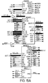
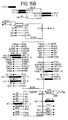
- Fig. 15 shows the primary ASIC 46 components.
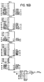
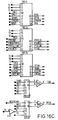
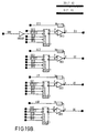
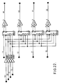
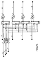
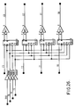
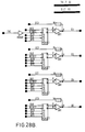
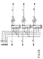
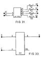
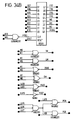
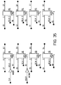
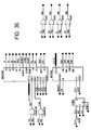
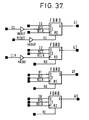
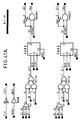
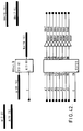
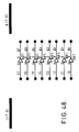
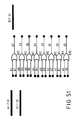
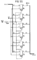
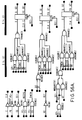
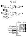
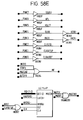
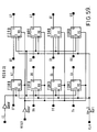
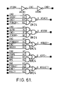
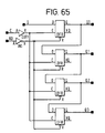
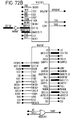
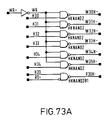
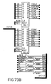
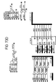
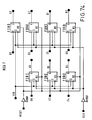
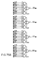
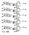
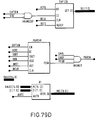
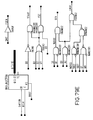
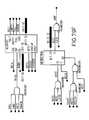
- Figs. 16-84 show the ASIC 46 circuitry at varying levels of further detail.
- Fig. 1 is a block diagram of a system 10 in accordance with the present invention.
- the system 10 transmits data signals from a base unit 12 at a first location to a peripheral device 14 (e.g., a printer) connected to a remote unit 16 at a second location.
- the base unit 12 has a terminal 18 for receiving the data signals to be transmitted.
- the base unit 12 modulates the data signals received at the terminal 18 to produce a facsimile-encoded data signal.
- the data signals are modulated according to a facsimile error correcting protocol, such as CCITT T.4 and T.434.
- the base unit 12 also generates a base-to-remote facsimile-encoded control signal.
- the base unit 12 provides the base-to-remote facsimile-encoded control signal and the facsimile-encoded data signal to an output terminal 20, to be transmitted to the remote unit 16, in the same session, via a public carrier network.
- the public carrier network may be, for example, a Public Switched Telephone Network ("PSTN", provided by a public carrier such as AT&T or Pacific Bell) or an Integrated Services Digital Network ("ISDN").
- PSTN Public Switched Telephone Network
- ISDN Integrated Services Digital Network
- the remote unit 16 receives, at an input terminal 22, the base to remote facsimile encoded control signal and the facsimile encoded data signal from the public carrier network.
- the remote unit 16 has one or more connectors for connecting one or more peripheral devices 14 to the remote unit 16.
- a printer 14 is shown as the peripheral device 14 connected to the remote unit 16.
- the peripheral device may also be, for example, a computer, to which the data signals can be uploaded, or a plotter.
- FIG. 1 Also shown in Fig. 1 is an apparatus 24 that creates the data signals to be transferred from the base unit 12 to the remote unit 16.
- the apparatus 24 may be an x86-based personal computer executing the Microsoft Windows operating system.
- an application program 26 e.g., Microsoft Word
- the data signal file would be formatted by a print driver program 30 (well known in the art) for a particular type of printer (e.g., an HP LaserJet III).
- a print spooler 33 e.g., Windows Print Manger
- the application program 26, the printer driver 30, and the print spooler 33 are conventional.
- a remote print driver program 34 captures, from the print spooler 33, the data signals which could otherwise be locally printed to an attached printer (not shown, but which would be connected to the apparatus 24 much like the base unit 12).
- the data signals captured by the printer driver 34 may be a binary file which is destined to a computer which is a peripheral connected to the remote unit 16.
- the binary file may be, for example, specified by a user responsive to prompts from the remote printer driver.
- the remote printer driver 34 provides a telephone number and scheduling information (e.g. time to send) to the base unit 12 via the input terminal 18.
- the base unit 12 then initiates a call via the public carrier network to establish a communication link between the base unit 12 and the remote unit 16.
- the remote unit 16 and the base unit 12 initiate a "handshake" routine in accordance with well-known facsimile protocols.
- the remote unit 16 Before the base unit 12 and remote unit 16 establish the parameters of the session (e.g. the baud rate), the remote unit 16 generates, and transmits to the base unit 12, a remote-to-base facsimile-encoded control signal that indicates the peripheral device or devices connected to the remote unit. For example, if the peripheral device 14 is an HP LaserJet III printer, the remote-to-base facsimile-encoded control signal will so indicate.
- the remote-to-base facsimile encoded control signal generated by the remote unit 16 identifies that the remote unit 16 is a compatible remote device (i.e. one which can direct a facsimile encoded data signal to a particular peripheral device represented by a base to remote facsimile encoded control signal). If the base unit 12 does not receive such an indication, then the remote transfer session is terminated.
- the base unit 12 determines, from the received remote-to-base facsimile-encoded control signal, whether a particular desired peripheral device is connected to the remote unit 16. If not, the remote transfer session is terminated. For example, if the application program 26 formatted a data signal file for printing to a HP LaserJet III, or for binary transfer to a computer, and the remote-to-base control signal indicates that only an Epson FX Printer is connected to the remote unit, the base unit 12 will terminate the remote transfer session.
- the base unit 12 may allow the remote transfer session to continue if the peripheral device 14 indicated in the remote-to-base control signal is indicated as being one which is a superset of the optimally-desired format.
- a data signal file formatted for printing on an HP LaserJet III printer may also be printed on an HP LaserJet+ printer, even though the HP LaserJet+ printer may not recognize all of the printer commands embedded in the data signal file.
- the remote print driver 34 records, in a location associated with the remote unit 16 phone number, the existence or non-existence of the particular desired type of peripheral device.
- the user can be informed, even before a call is placed, that on previous attempts this type of peripheral device 14 was not found at the remote unit 16 with this phone number. Since it is possible that the peripheral device 14 may now be found, the user is given an opportunity to have the call placed anyway.
- the remote unit 16 prints the received facsimile encoded data signal to the peripheral printer 14 in a bitmap format at 200 dpi. That is, the remote unit 16 can function as a conventional facsimile machine.
- Figs. 2-11 are flowcharts which illustrate the details of the processing within a particular embodiment of the invention.
- the following abbreviations are used throughout the flowcharts: BFT Binary File Transfer CCITT International Telephone and Brass Consultive Committee (now ITU) DB Database DCN Disconnect ECM Error Correcting Mode ISDN Intergrated Services Digital Network NSF Non-Standard Facilities NSS Non-Standard Setup PSTN Public Switched Telephone Network RP Remote Print RX Receive TX Transmit UI User Interface
- step 1 of the flowchart of Fig. 2 the remote print manager begins to execute.
- the remote print manager supervises the operations of the remote print driver 34.
- step 2 the remote print driver 34 sets up an interface to the print spooler 33.
- step 3 the remote print driver 34 sets up an interface to the base unit 12.
- step 4 a data signal file is created by the application 26 and formatted for a particular printer by the printer driver 30, and spooled by the print spooler 33.
- the remote print driver 34 captures the print-formatted data signals from the print spooler 33.
- step 5 the print-formatted data signals are transferred by the remote print driver 34 to the base unit 12.
- both the facsimile-encoded control signal and the base-to-remote facsimile-encoded data signal are transferred to the remote unit 16 via a public carrier network in a single session.
- the remote unit 16 provides to the base unit 12 the remote-to-base facsimile-encoded control signal and receives from the base unit 12 the base-to-remote facsimile-encoded control signal and the facsimile-encoded data signals.
- the remote print driver 34 removes the interface to the base unit 12 which was installed in step 3.
- the remote print driver 34 removes the interface to the print spooler 33 which was set up in step 2.
- the print manager 33 ceases to execute.
- Figs. 3-7 are flowcharts which show the details of the Fig. 2 step 4 processing within the remote print driver 34 for capturing data signals from the print spooler 33, including beginning a print job (Fig. 3), printing buffers (Fig. 4), ending a print job (Fig. 5), and deleting a print job (Fig. 6).
- Fig. 7 shows the processing within the remote print driver 34 for scheduling a transfer of data signals to the base unit 12.
- Fig. 8 is a flowchart which shows the details of the user interface (Ul) to the remote print driver 34. As can be seen from Fig. 8, the remote print driver has extensive error detection capabilities.
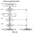
- Fig. 9 is a flowchart which shows the processing within the base unit 12 and the remote print driver for verifying from the remote-to-base control signal that the desired peripheral is connected to the remote unit 16.
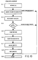
- Fig. 10 is a flowchart which shows the processing within remote unit 16.
- the remote unit 16 answers the call from the base unit 12 and transmits the remote-to-base control signal to the base unit 12 to inform the base unit 12 that the remote unit 16 is one which can generally direct a facsimile-encoded data signal to a particular peripheral device represented by a base-to-remote facsimile-encoded data signal and to inform the base unit of the particular peripheral or peripherals connected to the remote unit 16.
- the remote unit 16 receives the facsimile-encoded data signal from the base unit 12.
- the remote unit 16 decodes the data signals (i.e. strips the facsimile headers) and directs the data signals to the peripheral device represented by the base-to-remote facsimile-encoded control signal.
- Fig. 11 shows the details of the processing within the remote unit 16 in step 6.2 of Fig. 10.
- a base unit 12 and a remote unit 16 are combined into a single unit 41 at a first location for communication of data signals and control signals with a similarly combined unit 41 comprising a remote unit 16 and a base unit 12, respectively, at a second location.
- executable software is stored in an EPROM 40 for execution by a CPU 42, both of which are attached to an ADDRESS bus and a DATA bus.
- the CPU is a 80188 microprocessor, available from Intel or AMD.
- a RAM 44 also attached to the ADDRESS bus and the DATA bus, provides working memory.
- An Application Specific Integrated Circuit provides circuitry for the CPU to interface to a first buffer 48 of a parallel port 49 (to which a computer, as a peripheral 14, may be attached); to a second buffer 50 of a second parallel port 51 (to which a printer, as a peripheral 14, may be attached); to an EIA transceiver 52 which controls a serial port 54; to a first driver 56 of a light source 58; to a second driver 60 of a stepper motor 62 of a paper feeder; and to a keyboard 64 which interfaces to an LCD 66.
- a real time clock (“RTC”) 68 and a scanner 70, attached to a charge coupling device 72, are also attached to the ADDRESS bus and the DATA bus.
- a modem 74 attached to the ADDRESS bus and the DATA bus is connected to a Digital Analog Access (“DAA”) interface 76 to a phone line.
- DAA Digital Analog Access
- the signal from the apparatus 24 is received by the parallel port 49.
- Software in the EPROM 40 executed by the CPU 42, generates a header signal which contains a control signal, depending upon the printer desired.
- the control signal when facsimile encoded, becomes the facsimile encoded control signal.
- the software in the EPROM 40 executed by the CPU 42, directs the control signal and the data signal through the ASIC 46 to the modem 74.
- the modem 74 modulates the control signal and the data signal supplied thereto in accordance with the facsimile protocol and supplies the modulated signals to the DAA 76, to the public carrier network.
- the signal from the public carrier network is received by the DAA 76 and the modem 74.
- the signal is then demodulated and processed by the software in the EPROM 40 executed by the CPU 42. If there is no control signal in the header, the demodulated data signal is decompressed and is supplied to the second parallel port 51 as a "conventional" facsimile image. If there is a control signal, then the control signal is used by the CPU 42 to direct the data signal, uninterpreted, to the buffer 50 to the second parallel port 51.
- FIG. 13 shows the top-level ASIC printouts, including buffers and inverter circuitry.
- Fig. 14 shows the signals of the DAA interface 76, RAM 44 control, stepper motor 62 control, scanner 70 control, RTC 68 control, and parallel port 49 and 51 control.
- Fig. 15 shows the details of the main ASIC components, including NFAXBLK for controlling the modem 74, a speaker, the DAA 76, an answering machine line, and related connectors.
- NPPORT controls the parallel interfaces 49 and 51.
- KBDCTRL controls the keyboard 64, including the LCD 66.
- GAUART controls the serial communications of the EIA transceiver 52.
- the remaining blocks are address latches, decoders, multiplexers, and related glue logic.
- Figs. 16-84 show the ASIC circuitry at varying levels of further detail.
- Appendices A-F contain software code, in the "C" programming language.
- a portion of the software code resides in the EPROM 40 and executes on the CPU 42 for performing some of the steps of the flowcharts of Figs. 2-11.
- Another portion of the software code resides and executes in the apparatus 24 for performing others of the steps of the flowcharts of Figs. 2-11.
- references in the software code to software functions that are not included in the appendices. These non-included software functions are either conventional or are not relevant to the present invention.
- "HDB Get Record" in file BFTTX.C is a conventional function to retrieve a record from a data base.
- PARSE_FHS displays a message on a liquid crystal display.
- Appendix A contains a "header” file, BFT.H, which provides common data and structure definitions for the software modules in Appendices B-D, including definition of a "non-standard frame" in which facsimile-encoded control signals are communicated between the base unit 12 and the remote unit 16. This software is shared between the EPROM 40 and the apparatus 24.
- Appendix B contains a software module "RP.C”.
- the individual files contain software for the remote print driver 34 to set up and remove the interface to the print spooler 33 (steps 2 and 8 of the flowchart in Fig. 2) and for beginning a print job (steps 4.1.1 to 4.1.5 of the flowchart in Fig. 3). This software is used only by the apparatus 24.
- Appendix C contains a software module "RPPORTS.C".
- the individual files contain software for the remote print driver 34 to set up and remove an interface to the base unit 12 (steps 3 and 7 of the flowchart in Fig. 2).
- RPPORTS.C also has software for the user interface to the remote print driver 34 (steps 4.5.2 to 4.5.5 of the flowchart in Fig. 7).
- User specified data is stored in a database, "DB_PBK”. This software is used only by the apparatus 24.
- Appendix D contains a software module "BFTTX.C".
- the individual files contain software for initializing the base unit 12 and remote unit 16 (step 5.1 in the flowchart of Fig. 8); for verifying the remote capabilities (step 5.4 in the flowchart of Fig. 8, including steps 5.4.1 to 5.4.7 in the flowchart of Fig. 9); for composing and sending control signals (step 5.5. in the flowchart of Fig. 8); for handling the details of the processing within the remote unit 16 (steps 6.2 to 6.4 and 6.7 in the flowchart of Fig. 10, including steps 6.2.3 to 6.2.5 in the flowchart of Fig. 11).
- This software is shared between the EPROM 40 and the apparatus 24.
- Appendix E contains a software module "BFT.C".
- the software within this module handles remote unit 16 processing, including answering a call and exchanging facsimile capabilities (step 6.2 in the flowchart of Fig. 10) and facsimile receive (step 6.3 in the flowchart of Fig. 10).
- the software within this module also performs file handling and call progress during a data signal transfer (steps 5.2 and 5.5 to 5.7 in the flowchart of Fig. 8) and upload to a computer (step 6.2.6 in the flowchart of Fig. 11). This software is used only in the EPROM 40.
- Appendix F contains a software module "MCTFAX.C" which contains software to directly manages an ongoing data signal transfer, including dialing, parameter negotiation, session monitoring, and transfer of the transferred data signals from the remote unit 16 to a connected peripheral 14 (steps 5.3 and 5.7 to 5.9 in the flowchart of Fig. 8; step 6.1 and 6.5 to 6.8 in the flowchart of Fig. 10; and steps 6.2.2 and 6.2.7 to 6.2.9 in the flowchart of Fig. 11).
- This software is used only in the EPROM 40.
- the remote unit 16 can receive a standard facsimile transmission, and print that transmitted document, in facsimile image on the associated remote printer 14.
- the remote unit 16 can also receive facsimile encoded signal from the base unit 12, and print them on the associated printer 14, in the same print quality as if the printer 14 were locally connected to the apparatus 24.
- the base unit 12 can even direct the printing of the signals to one of a plurality of possibly connected remote printers 14 (if a plurality were so connected).
Landscapes
- Engineering & Computer Science (AREA)
- Multimedia (AREA)
- Signal Processing (AREA)
- General Engineering & Computer Science (AREA)
- Facsimiles In General (AREA)
Applications Claiming Priority (2)
| Application Number | Priority Date | Filing Date | Title |
|---|---|---|---|
| US33234894A | 1994-10-31 | 1994-10-31 | |
| US332348 | 1994-10-31 |
Publications (2)
| Publication Number | Publication Date |
|---|---|
| EP0719030A2 true EP0719030A2 (de) | 1996-06-26 |
| EP0719030A3 EP0719030A3 (de) | 1996-08-14 |
Family
ID=23297835
Family Applications (1)
| Application Number | Title | Priority Date | Filing Date |
|---|---|---|---|
| EP95307725A Withdrawn EP0719030A3 (de) | 1994-10-31 | 1995-10-30 | Gerät zur faksimilekodierten Übertragung von Datensignalen |
Country Status (2)
| Country | Link |
|---|---|
| EP (1) | EP0719030A3 (de) |
| TW (1) | TW288243B (de) |
Family Cites Families (2)
| Publication number | Priority date | Publication date | Assignee | Title |
|---|---|---|---|---|
| US4900902A (en) * | 1985-12-19 | 1990-02-13 | Canon Kabushiki Kaisha | Data communication apparatus |
| EP0484145B1 (de) * | 1990-10-31 | 1997-04-02 | Hewlett-Packard Company | Ferndrucker mit Fax |
-
1995
- 1995-04-01 TW TW84103278A patent/TW288243B/zh active
- 1995-10-30 EP EP95307725A patent/EP0719030A3/de not_active Withdrawn
Non-Patent Citations (1)
| Title |
|---|
| None |
Also Published As
| Publication number | Publication date |
|---|---|
| EP0719030A3 (de) | 1996-08-14 |
| TW288243B (de) | 1996-10-11 |
Similar Documents
| Publication | Publication Date | Title |
|---|---|---|
| WO1993025041A1 (en) | A facsimile device | |
| US5140439A (en) | Facsimile communication method and facsimile machine | |
| US6809836B1 (en) | Image communication apparatus and its control method | |
| KR100193793B1 (ko) | 팩시밀리의 메세지 처리방법 | |
| US6982806B2 (en) | Facsimile apparatus, control method for facsimile apparatus, and computer-readable storage medium storing control program for facsimile apparatus | |
| US7019855B1 (en) | Method for informing a transmitting module of error occurrence in a receiving part of a facsimile | |
| GB2303020A (en) | Fax document re-transmission method | |
| EP0719030A2 (de) | Gerät zur faksimilekodierten Übertragung von Datensignalen | |
| US6762850B2 (en) | Facsimile apparatus | |
| EP0917346A2 (de) | Koordination der Auflösungen von Faksimilegeräten | |
| US7227654B1 (en) | Method and apparatus for group 3 facsimile capable of properly performing a communications operation using optional frames | |
| KR0130874B1 (ko) | 팩시밀리의 프로토콜 송수신방법 | |
| KR100264324B1 (ko) | 팩스 데이터의 전송상태를 확인하는 장치 및 방법 | |
| JPH0897945A (ja) | データ通信装置 | |
| JP6828699B2 (ja) | ファクシミリ装置及びファクシミリ通信システム | |
| JP3633553B2 (ja) | リモートコピー機能を備えた通信端末装置 | |
| JP2792920B2 (ja) | ファクシミリ通信方式 | |
| JP2629636B2 (ja) | ファクシミリ装置 | |
| JP2001320590A (ja) | カラーファクシミリ装置 | |
| KR100247071B1 (ko) | 팩시밀리장치에서 수신결과를 송신국으로 통보하는 방법 | |
| KR0165204B1 (ko) | 팩시밀리 가입자의 영문자 정보교환방법 | |
| KR100223001B1 (ko) | 교신시간 단축방법 | |
| KR100245024B1 (ko) | 팩시밀리의 메모리 송/수신방법 | |
| KR100325817B1 (ko) | 메모리 잔량에 따른 해상도 변환방법 | |
| KR19980074587A (ko) | 팩시밀리의 송신페이지 전송방법 |
Legal Events
| Date | Code | Title | Description |
|---|---|---|---|
| PUAI | Public reference made under article 153(3) epc to a published international application that has entered the european phase |
Free format text: ORIGINAL CODE: 0009012 |
|
| AK | Designated contracting states |
Kind code of ref document: A2 Designated state(s): DE FR GB IT |
|
| PUAL | Search report despatched |
Free format text: ORIGINAL CODE: 0009013 |
|
| AK | Designated contracting states |
Kind code of ref document: A3 Designated state(s): DE FR GB IT |
|
| 17P | Request for examination filed |
Effective date: 19970213 |
|
| STAA | Information on the status of an ep patent application or granted ep patent |
Free format text: STATUS: THE APPLICATION IS DEEMED TO BE WITHDRAWN |
|
| 18D | Application deemed to be withdrawn |
Effective date: 19980501 |