EP0719083B1 - Appareil de manutention du fourrage - Google Patents
Appareil de manutention du fourrage Download PDFInfo
- Publication number
- EP0719083B1 EP0719083B1 EP94927030A EP94927030A EP0719083B1 EP 0719083 B1 EP0719083 B1 EP 0719083B1 EP 94927030 A EP94927030 A EP 94927030A EP 94927030 A EP94927030 A EP 94927030A EP 0719083 B1 EP0719083 B1 EP 0719083B1
- Authority
- EP
- European Patent Office
- Prior art keywords
- limbs
- limb
- silage
- pivot
- towards
- Prior art date
- Legal status (The legal status is an assumption and is not a legal conclusion. Google has not performed a legal analysis and makes no representation as to the accuracy of the status listed.)
- Expired - Lifetime
Links
Images

Classifications
-
- A—HUMAN NECESSITIES
- A01—AGRICULTURE; FORESTRY; ANIMAL HUSBANDRY; HUNTING; TRAPPING; FISHING
- A01K—ANIMAL HUSBANDRY; AVICULTURE; APICULTURE; PISCICULTURE; FISHING; REARING OR BREEDING ANIMALS, NOT OTHERWISE PROVIDED FOR; NEW BREEDS OF ANIMALS
- A01K1/00—Housing animals; Equipment therefor
- A01K1/10—Feed racks
- A01K1/105—Movable feed barriers
Definitions
- the present invention relates to an apparatus for moving silage and in particular for pushing silage blocks.
- a type of apparatus for moving silage in a cow shed consists of two silage pushing members linked together to a main frame, whereby the linkage to the main frame is by means of a parallelogram which keeps the pushing members perpendicular to it.
- a tractor unit which carries the frame penetrates the silage mass by reversing along the feeding passage, and by opening the feeding members push the silage towards the barrier. Since this frame is not propelled manually as with apparatus 1 and apparatus 1', it therefore needs a wide passageway to manoeuvre and move silage appropriately, therefore the width of the apparatus alone defeats what it is endeavouring to achieve.
- the minimum width of the passage is equal to the width of the tractor plus twice the width of the blocks or round bales it is endeavouring to push.
- the tractor and its appending apparatus would slew around in an arc about the centre of the tractors rear axle. Therefore the apparatus cannot push the silage forwardly toward the barrier.
- Yet another type of apparatus is the actual feeding barrier which moves forwardly towards the silage when the animals push it. It therefore follows that the animals control what they eat which would not be very satisfactory and would lead to a lot of wastage. It also means that one such structure must be fitted for every pen in the shed.
- the present invention seeks to alleviate the disadvantages associated with the above.
- the present invention accordingly provides an apparatus for pushing silage blocks comprising a silage block engaging portion, a pushing limb and a stabilising limb pivotally attached to said pushing limb and means for moving the pushing limb relative to the stabilising limb.
- the means for moving the pushing limb relative to the stabilising limb comprises only one hydraulic ram.
- the apparatus may conveniently include anchoring members.
- the apparatus includes two swivel castors mounted on the pushing limb and two swivel castors mounted on the stabilising limb.
- the apparatus is indicated generally by the reference numeral 1.
- This apparatus 1 is suitable for use in single slatted houses or cattle sheds, for example.
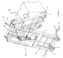
- the apparatus 1 is an inverted "V" type frame including a forward pushing limb 3 attached about a pivot 10 to a rear stabilising limb 2.
- a forward pushing limb 3 attached about a pivot 10 to a rear stabilising limb 2.
- the forward limb 3 and the rear stabilising limb 2 are in the vertical and free standing on the swivel castors 6. This is one of the primary and most important features of the apparatus 1, since it narrows or reduces in width, so that it can negotiate the narrow space or path between the wall and feed in order to push the silage towards the barrier.
- Apparatus 1 and 1' is wheeled manually, is not attached in any way to a tractor, is totally independent, is extremely manoeuvrable on its four independent swivel castors 6 which allow it to move in any desired direction, and its minimum width when members 2 and 3 are in the vertical is 0.5 metres thereby allowing it into very narrow confines.
- valve 23 When it is desired to feed the cattle, valve 23 is activated by the operator to retract limbs 2 and 3 in order to bring apparatus 1 to its minimum width so that it can be manually pushed towards and between the first block or bale 100 and the wall in the side feeding passage.
- the operator When in position, the operator activates the hand control valve 23.
- the hydraulic ram 12 pushes members 2 and 3 apart about pivot 10.
- Limb 3 contacts the silage block via the silage block engaging portion 5.
- limb 2 will experience a resultant backward force until anchoring members 4 which are attached to limb 2 contact the wall of the single slatted seed.
- the hydraulic ram extends the silage block 100 will be pushed towards the barrier. In this way the operator can control the amount of feed given to the animals.
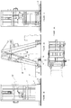
- FIG. 1 This apparatus is indicated generally by the reference numeral 1' and operates in a similar manner to the apparatus 1 already described above except that apparatus 1' is also suitable for use in a double slatted shed.
- the feeding passage is situated along the full length and in the centre of the shed.
- the feeding barriers are both to the left and right of the passage way.
- Apparatus 1' is again an inverted "V" type frame including a forward pushing limb 3 attached about a pivot 10 to a rear stabilizing limb 2, swivel castors 6, a block or bale engaging portion 5, rectangular cross members 57 located at the bases of limbs 2 and 3 but free to rotate around hidden axles, and struts 50 which are pivotally attached to said rectangular cross members 57.
- the struts are pivotally attached in an opposing fashion at the top of said limbs 2 and 3. This gives a parallelogram effect which ensures that irrespective of how much limbs 2 and 3 move apart or together at their bases, the rectangular crossmembers 57 will always remain in the horizontal.
- Engaging portion 5 is pivotally and vertically attached to crossmember 57 on limb 3. Engaging portion 5 is therefore at right angles to the silage passage floor for all movements of limb 3 whether towards or away from limb 2.
- Apparatus 1' includes a hydraulic Powerpack, ram and hand control valve combination 12 and 58, hooks 52 which rotate about a hidden axle and hook onto the heavy duty tube 51.
- Tube 51 lies on the floor of the feeding passage in the centre of the passage. Tube 51 runs along the full length of the passage parallel to the feeding barriers and is rawbolted or pinned to the centre passage floor.
- the control valve 23 is activated to retract limbs 2 and 3 into the vertical. Apparatus 1' will then be at its minimum width. The apparatus 1' is then manually pushed towards and between opposing block rows but with the forward pushing member 3 on one side of the tube 51 and the stabilizing member 2 on the other side of said tube. Hooks 52 on the base of stabilizing member 2 are rotated and engaged around the tube 51 by the operator, using his foot, thereby holding limb 2 in a fixed position. The operator activates the control valve 23 and limb 3 moves outwardly under the action of the hydraulic ram 12 from the fixed limb 2. As limb 3 moves outwardly the engaging portion 5 thereof contacts the silage block or bale 100 and pushes it towards the feed barrier.
- Apparatus 1 and apparatus 1' may not be confined to cattle sheds in order to do work. Apparatus 1 and Apparatus 1' could be used in many situations in order to move many materials - materials on pallets, materials in warehouses etc.
Landscapes
- Life Sciences & Earth Sciences (AREA)
- Environmental Sciences (AREA)
- Zoology (AREA)
- Animal Husbandry (AREA)
- Biodiversity & Conservation Biology (AREA)
- Fertilizing (AREA)
- Feeding And Watering For Cattle Raising And Animal Husbandry (AREA)
- Pipe Accessories (AREA)
Claims (9)
- Appareil (1) de déplacement du fourrage ensilé et autres matériaux qui est tiré ou poussé manuellement sur toute la longueur du couloir d'avancée, comprenant des branches stabilisatrices (2, 3) attachées de manière à pivoter en leur partie supérieure et formant un "V" inversé autour du pivot (10), un élément d'ancrage (4), une partie d'engagement de la botte de fourrage (5), des roues pivotantes (6), un piston hydraulique (12) actionné par un moteur électrique, une pompe hydraulique (21) et une vanne de contrôle (23) pour écarter les branches (2) et (3).
- Appareil (1) tel que revendiqué dans la revendication (1), pour lequel lorsque la branche (2) est placée contre un objet fixe tel qu'un mur et qu'un mouvement angulaire intervient entre les branches (2) et (3) autour du pivot (10), la branche (3) s'éloigne de la branche (2) pour engager et pousser l'avance vers la barrière.
- Appareil pour déplacer le fourrage ensilé (1) tel que revendiqué dans les revendications (1) et (2), pour lequel le bras (56), lorsqu'il est tourné pour passer a l'horizontale, vient s'appuyer contre un objet fixe tel qu'un mur, augmentant ainsi la largeur de l'appareil (1) afin de réduire le mouvement angulaire entre les branches (2) et (3), accélérant ainsi la procédure d'alimentation.
- Appareil (1) tel que revendiqué dans les revendications (1), (2) et (3), pour lequel lorsque la branche (2) est accrochée autour des crochets (52) à la tuyauterie ou au tube (51) qui repose lui-même sur le sol du passage de l'avance auquel il est boulonné et qu'un mouvement angulaire intervient entre les branches (2) et (3) autour du pivot (10), la branche (3) s'écarte de la branche (2) pour engager et pousser le fourrage ensilé vers le bétail.
- Appareil (1) tel que revendiqué dans les revendications (1), (2), (3) et (4), pour lequel lorsque la botte de fourrage est poussée vers la barrière, les branches (2) et (3) s'escamotent autour du pivot (10) de sorte que l'appareil (1) peut alors être poussé manuellement vers et derrière la botte ou la balle suivante pour répéter la procédure d'alimentation.
- Appareil (1) tel que revendiqué dans les revendications (1), (2), (3), (4) et (5), pour lequel les branches (2) et (3) se déplacent vers l'extérieur et vers l'intérieur autour du pivot (10) au moyen d'une combinaison formée d'un bloc d'alimentation hydraulique (21), d'un piston et d'une vanne de contrôle manuel.
- Appareil (1) tel que revendiqué dans la revendication (6), pour lequel lorsque les branches (2) et (3) se déplacent vers l'intérieur autour du pivot (10) jusqu'à leur position intérieure maximale, les branches (2) et (3) sont alors à la verticale, laissant donc l'appareil (1) en position de largeur minimale pour permettre un accès facile aux espaces étroits existant entre le mur et l'avance ou entre les rangées d'avance.
- Appareil (1) tel que revendiqué dans la revendication (1), pour lequel l'appareil (1) est porté et se déplace sur des roues pivotantes (6) qui sont fixées à des traverses (57).
- Appareil (1) tel que revendiqué dans les revendications (1) et (9), pour lequel les traverses (57) font une rotation ou pivotent sur les extrémités inférieures des branches (2) et (3) grâce à des essieux cachés mais sont attachées au moyen de tiges ou d'étais (50) qui sont eux-mêmes fixés de manière à pivoter et sont parallèles aux branches (2) et (3) respectivement en haut, garantissant ainsi que les traverses (57) restent toujours à l'horizontale pour garder les roues pivotantes (6) et l'élément de poussage du fourrage ensilé (5) à la verticale.
Applications Claiming Priority (3)
| Application Number | Priority Date | Filing Date | Title |
|---|---|---|---|
| IES930713 IES65646B2 (en) | 1993-09-23 | 1993-09-23 | Apparatus for moving silage |
| IE930713 | 1993-09-23 | ||
| PCT/IE1994/000046 WO1995008264A1 (fr) | 1993-09-23 | 1994-09-20 | Appareil de manutention du fourrage |
Publications (2)
| Publication Number | Publication Date |
|---|---|
| EP0719083A1 EP0719083A1 (fr) | 1996-07-03 |
| EP0719083B1 true EP0719083B1 (fr) | 1998-05-27 |
Family
ID=11040100
Family Applications (1)
| Application Number | Title | Priority Date | Filing Date |
|---|---|---|---|
| EP94927030A Expired - Lifetime EP0719083B1 (fr) | 1993-09-23 | 1994-09-20 | Appareil de manutention du fourrage |
Country Status (5)
| Country | Link |
|---|---|
| EP (1) | EP0719083B1 (fr) |
| DE (1) | DE69410620T2 (fr) |
| DK (1) | DK0719083T3 (fr) |
| IE (1) | IES65646B2 (fr) |
| WO (1) | WO1995008264A1 (fr) |
Families Citing this family (2)
| Publication number | Priority date | Publication date | Assignee | Title |
|---|---|---|---|---|
| DE29600192U1 (de) * | 1996-01-08 | 1996-03-07 | Hofacker, Hubert, 78199 Bräunlingen | Futterschiebevorrichtung zum Zuschieben von Viehfutter, insbesondere von Futterblöcken, zu einem Freßgitter |
| AT405476B (de) * | 1997-12-23 | 1999-08-25 | Wasserbauer Ludwig Franz | Fütterungsvorrichtung für einen stall |
Family Cites Families (4)
| Publication number | Priority date | Publication date | Assignee | Title |
|---|---|---|---|---|
| EP0043098A1 (fr) * | 1980-06-26 | 1982-01-06 | B. Strautmann & Söhne GmbH & Co. | Dispositif pour déplacer du fourrage ensilé en blocs |
| GB8803518D0 (en) * | 1988-02-16 | 1988-03-16 | Shepherd D H | Materials moving apparatus |
| US4951608A (en) * | 1989-05-15 | 1990-08-28 | Reisgies Rolf W | Brisket bar apparatus for controlling the positioning and movement of cows in a milking parlor |
| GB2259437B (en) * | 1991-08-28 | 1995-12-20 | Southern Pharmaceutical Compan | A feeding barrier |
-
1993
- 1993-09-23 IE IES930713 patent/IES65646B2/en not_active IP Right Cessation
-
1994
- 1994-09-20 EP EP94927030A patent/EP0719083B1/fr not_active Expired - Lifetime
- 1994-09-20 DE DE69410620T patent/DE69410620T2/de not_active Expired - Fee Related
- 1994-09-20 WO PCT/IE1994/000046 patent/WO1995008264A1/fr not_active Ceased
- 1994-09-20 DK DK94927030T patent/DK0719083T3/da active
Also Published As
| Publication number | Publication date |
|---|---|
| WO1995008264A1 (fr) | 1995-03-30 |
| DE69410620T2 (de) | 1999-02-04 |
| DE69410620D1 (de) | 1998-07-02 |
| EP0719083A1 (fr) | 1996-07-03 |
| DK0719083T3 (da) | 1999-03-22 |
| IES930713A2 (en) | 1995-11-15 |
| IES65646B2 (en) | 1995-11-15 |
Similar Documents
| Publication | Publication Date | Title |
|---|---|---|
| US5333981A (en) | Bale loading, transporting and unloading trailer | |
| US5289798A (en) | Livestock handling/feeding apparatus and method | |
| CA1331880C (fr) | Appareil utilisant la force animale | |
| US5425221A (en) | Apparatus for loading flexible tubing with bales | |
| US6070400A (en) | Forage wrapping device and method | |
| EP0061817B1 (fr) | Râtelier mangeoire | |
| US5062757A (en) | Large round bale handling apparatus | |
| US4909694A (en) | Round bale trailer | |
| US4552501A (en) | Big bale handling system | |
| WO2000047443A1 (fr) | Distributeur de foin mecanique | |
| US3351151A (en) | Harvesting vehicle for supporting workers | |
| US3913529A (en) | Feeding pen for haystacks | |
| EP0719083B1 (fr) | Appareil de manutention du fourrage | |
| US5074733A (en) | Universal bale shuttle | |
| US5584637A (en) | Bale loader for truck with fold around arms | |
| US3985246A (en) | Bale retrieving and transporting apparatus | |
| US6394732B1 (en) | Bale handling device | |
| CA1091193A (fr) | Chariot a ballots | |
| US4521149A (en) | Bale handling machine | |
| US4162135A (en) | Quarter bale turning apparatus | |
| US7717660B1 (en) | Device and method for lifting and transporting conventional hay bale feeders with a round hay bale | |
| US6109856A (en) | Hay bale carrier | |
| KR101160099B1 (ko) | 볏짚 자동 급이기 | |
| US9232695B1 (en) | Round bale mover | |
| DE3533819C2 (fr) |
Legal Events
| Date | Code | Title | Description |
|---|---|---|---|
| PUAI | Public reference made under article 153(3) epc to a published international application that has entered the european phase |
Free format text: ORIGINAL CODE: 0009012 |
|
| 17P | Request for examination filed |
Effective date: 19960422 |
|
| AK | Designated contracting states |
Kind code of ref document: A1 Designated state(s): DE DK FR GB IE NL SE |
|
| GRAG | Despatch of communication of intention to grant |
Free format text: ORIGINAL CODE: EPIDOS AGRA |
|
| 17Q | First examination report despatched |
Effective date: 19970318 |
|
| GRAG | Despatch of communication of intention to grant |
Free format text: ORIGINAL CODE: EPIDOS AGRA |
|
| GRAG | Despatch of communication of intention to grant |
Free format text: ORIGINAL CODE: EPIDOS AGRA |
|
| GRAH | Despatch of communication of intention to grant a patent |
Free format text: ORIGINAL CODE: EPIDOS IGRA |
|
| GRAH | Despatch of communication of intention to grant a patent |
Free format text: ORIGINAL CODE: EPIDOS IGRA |
|
| GRAA | (expected) grant |
Free format text: ORIGINAL CODE: 0009210 |
|
| AK | Designated contracting states |
Kind code of ref document: B1 Designated state(s): DE DK FR GB IE NL SE |
|
| REF | Corresponds to: |
Ref document number: 69410620 Country of ref document: DE Date of ref document: 19980702 |
|
| REG | Reference to a national code |
Ref country code: IE Ref legal event code: FG4D |
|
| PG25 | Lapsed in a contracting state [announced via postgrant information from national office to epo] |
Ref country code: SE Free format text: LAPSE BECAUSE OF FAILURE TO SUBMIT A TRANSLATION OF THE DESCRIPTION OR TO PAY THE FEE WITHIN THE PRESCRIBED TIME-LIMIT Effective date: 19980827 |
|
| ET | Fr: translation filed | ||
| REG | Reference to a national code |
Ref country code: DK Ref legal event code: T3 |
|
| PLBE | No opposition filed within time limit |
Free format text: ORIGINAL CODE: 0009261 |
|
| 26N | No opposition filed | ||
| REG | Reference to a national code |
Ref country code: GB Ref legal event code: IF02 |
|
| PG25 | Lapsed in a contracting state [announced via postgrant information from national office to epo] |
Ref country code: FR Free format text: LAPSE BECAUSE OF NON-PAYMENT OF DUE FEES Effective date: 20060531 |
|
| REG | Reference to a national code |
Ref country code: FR Ref legal event code: ST Effective date: 20060531 |
|
| REG | Reference to a national code |
Ref country code: FR Ref legal event code: RN Ref country code: FR Ref legal event code: FC |
|
| PGRI | Patent reinstated in contracting state [announced from national office to epo] |
Ref country code: FR Effective date: 20080130 |
|
| PGFP | Annual fee paid to national office [announced via postgrant information from national office to epo] |
Ref country code: DK Payment date: 20080917 Year of fee payment: 15 |
|
| PGFP | Annual fee paid to national office [announced via postgrant information from national office to epo] |
Ref country code: NL Payment date: 20080918 Year of fee payment: 15 Ref country code: FR Payment date: 20080915 Year of fee payment: 15 |
|
| PGFP | Annual fee paid to national office [announced via postgrant information from national office to epo] |
Ref country code: DE Payment date: 20081120 Year of fee payment: 15 |
|
| REG | Reference to a national code |
Ref country code: NL Ref legal event code: V1 Effective date: 20100401 |
|
| REG | Reference to a national code |
Ref country code: DK Ref legal event code: EBP |
|
| REG | Reference to a national code |
Ref country code: FR Ref legal event code: ST Effective date: 20100531 |
|
| PG25 | Lapsed in a contracting state [announced via postgrant information from national office to epo] |
Ref country code: NL Free format text: LAPSE BECAUSE OF NON-PAYMENT OF DUE FEES Effective date: 20100401 Ref country code: FR Free format text: LAPSE BECAUSE OF NON-PAYMENT OF DUE FEES Effective date: 20090930 Ref country code: DE Free format text: LAPSE BECAUSE OF NON-PAYMENT OF DUE FEES Effective date: 20100401 |
|
| PGFP | Annual fee paid to national office [announced via postgrant information from national office to epo] |
Ref country code: IE Payment date: 20100914 Year of fee payment: 17 |
|
| PGFP | Annual fee paid to national office [announced via postgrant information from national office to epo] |
Ref country code: GB Payment date: 20100916 Year of fee payment: 17 |
|
| PG25 | Lapsed in a contracting state [announced via postgrant information from national office to epo] |
Ref country code: DK Free format text: LAPSE BECAUSE OF NON-PAYMENT OF DUE FEES Effective date: 20090930 |
|
| GBPC | Gb: european patent ceased through non-payment of renewal fee |
Effective date: 20110920 |
|
| REG | Reference to a national code |
Ref country code: IE Ref legal event code: MM4A |
|
| PG25 | Lapsed in a contracting state [announced via postgrant information from national office to epo] |
Ref country code: IE Free format text: LAPSE BECAUSE OF NON-PAYMENT OF DUE FEES Effective date: 20110920 |
|
| PG25 | Lapsed in a contracting state [announced via postgrant information from national office to epo] |
Ref country code: GB Free format text: LAPSE BECAUSE OF NON-PAYMENT OF DUE FEES Effective date: 20110920 |