EP0719416B1 - Integrierbarer tragflächenmessaufnehmer für die gesamttemperatur - Google Patents
Integrierbarer tragflächenmessaufnehmer für die gesamttemperatur Download PDFInfo
- Publication number
- EP0719416B1 EP0719416B1 EP94929234A EP94929234A EP0719416B1 EP 0719416 B1 EP0719416 B1 EP 0719416B1 EP 94929234 A EP94929234 A EP 94929234A EP 94929234 A EP94929234 A EP 94929234A EP 0719416 B1 EP0719416 B1 EP 0719416B1
- Authority
- EP
- European Patent Office
- Prior art keywords
- fluid
- strut
- cavity
- probe
- air data
- Prior art date
- Legal status (The legal status is an assumption and is not a legal conclusion. Google has not performed a legal analysis and makes no representation as to the accuracy of the status listed.)
- Expired - Lifetime
Links
- 239000012530 fluid Substances 0.000 claims description 96
- 239000000523 sample Substances 0.000 claims description 82
- 239000002245 particle Substances 0.000 claims description 7
- 230000008878 coupling Effects 0.000 claims description 6
- 238000010168 coupling process Methods 0.000 claims description 6
- 238000005859 coupling reaction Methods 0.000 claims description 6
- 238000010438 heat treatment Methods 0.000 claims description 5
- 230000005855 radiation Effects 0.000 claims description 2
- BASFCYQUMIYNBI-UHFFFAOYSA-N platinum Chemical compound [Pt] BASFCYQUMIYNBI-UHFFFAOYSA-N 0.000 claims 2
- 229910052697 platinum Inorganic materials 0.000 claims 1
- 230000003068 static effect Effects 0.000 description 5
- 238000005259 measurement Methods 0.000 description 2
- 238000011144 upstream manufacturing Methods 0.000 description 2
- 241000272517 Anseriformes Species 0.000 description 1
- 238000010276 construction Methods 0.000 description 1
- 230000003247 decreasing effect Effects 0.000 description 1
- 230000000694 effects Effects 0.000 description 1
- 238000011044 inertial separation Methods 0.000 description 1
- 239000000463 material Substances 0.000 description 1
- 238000012986 modification Methods 0.000 description 1
- 230000004048 modification Effects 0.000 description 1
- 230000003287 optical effect Effects 0.000 description 1
- 230000001681 protective effect Effects 0.000 description 1
- 238000002310 reflectometry Methods 0.000 description 1
- 238000000926 separation method Methods 0.000 description 1
- XLYOFNOQVPJJNP-UHFFFAOYSA-N water Substances O XLYOFNOQVPJJNP-UHFFFAOYSA-N 0.000 description 1
Images


Classifications
-
- G—PHYSICS
- G01—MEASURING; TESTING
- G01K—MEASURING TEMPERATURE; MEASURING QUANTITY OF HEAT; THERMALLY-SENSITIVE ELEMENTS NOT OTHERWISE PROVIDED FOR
- G01K13/00—Thermometers specially adapted for specific purposes
- G01K13/02—Thermometers specially adapted for specific purposes for measuring temperature of moving fluids or granular materials capable of flow
- G01K13/028—Thermometers specially adapted for specific purposes for measuring temperature of moving fluids or granular materials capable of flow for use in total air temperature [TAT] probes
-
- G—PHYSICS
- G01—MEASURING; TESTING
- G01K—MEASURING TEMPERATURE; MEASURING QUANTITY OF HEAT; THERMALLY-SENSITIVE ELEMENTS NOT OTHERWISE PROVIDED FOR
- G01K13/00—Thermometers specially adapted for specific purposes
- G01K13/02—Thermometers specially adapted for specific purposes for measuring temperature of moving fluids or granular materials capable of flow
-
- G—PHYSICS
- G01—MEASURING; TESTING
- G01P—MEASURING LINEAR OR ANGULAR SPEED, ACCELERATION, DECELERATION, OR SHOCK; INDICATING PRESENCE, ABSENCE, OR DIRECTION, OF MOVEMENT
- G01P5/00—Measuring speed of fluids, e.g. of air stream; Measuring speed of bodies relative to fluids, e.g. of ship, of aircraft
- G01P5/14—Measuring speed of fluids, e.g. of air stream; Measuring speed of bodies relative to fluids, e.g. of ship, of aircraft by measuring differences of pressure in the fluid
- G01P5/16—Measuring speed of fluids, e.g. of air stream; Measuring speed of bodies relative to fluids, e.g. of ship, of aircraft by measuring differences of pressure in the fluid using Pitot tubes, e.g. Machmeter
- G01P5/165—Arrangements or constructions of Pitot tubes
Definitions
- the present invention relates to air data sensing probes usable on air vehicles.
- the present invention includes air data sensing probes integrated into a portion of an airfoil, such as a strut of an L-shaped air data probe or a portion of an air vehicle wing or canard.
- air data probes for sensing and measuring properties of a fluid medium near an air vehicle preferably protrude from the air vehicle to detect relatively undisturbed air flow to register accurate air data.
- duplicate sensors for such flight-critical information ensure that back-up systems are available in case of failure of a system.
- each probe adds aerodynamic drag, weight, complex electrical and, often, pneumatic coupling as well as radar reflectivity.
- US-A-4 730 487 illustrates a multiple static pressure measuring system which includes a probe having an elongate body with surface irregularities on its outer surface for providing flow disruption for adequate compensation for measuring pressure at different locations along the probe as well as total pressure at a port at the leading end of the probe. This probe only measures pressure.
- US-A-5 025 661 describes a combination air data probe which is intended to have the capability of performing measurements from a single structure of both total temperature and total pressure. It has a direct port which bleeds off a portion of the fluid flow to pass it over the temperature sensing element.
- EP-A-0 287 223 proposes an air data measurement device located upon a strut which device has an elongate housing that is open at both ends to provide respectively for fluid intake and discharge, and which is divided into two chambers by a transverse wall.
- the chamber receiving fluid intake contains a total pressure sensor, whilst the chamber from which fluid is discharged contains a total temperature sensor.
- an air data probe for sensing parameters of a fluid moving relative to the probe, comprising an aerodynamic strut having a leading edge and trailing edge, at least one inlet aperture formed at the leading edge of the strut, and a primary cavity fluidly coupled to the at least one inlet aperture at a first end and fluidly coupling to at least one exhaust port, and further having a secondary fluid cavity in the strut fluidly coupled to a first portion of the primary fluid cavity, and extending laterally away from the primary fluid cavity, the secondary fluid cavity being coupled to a fluid discharge port opening to an area of reduced fluid pressure, temperature sensing means disposed in the secondary fluid cavity for detecting a temperature parameter of the fluid moving therethrough and providing an output signal, and a porous wall portion forming an interior surface of at least an inlet portion of
- the exterior walls of the strut provide the interior wall surfaces of a first portion of the primary cavity, and the second portion of the primary cavity comprises an elongated duct connected to an exhaust port(s) in a low pressure area downstream from the inlet port.
- the temperature sensing means is suitably isolated within the secondary cavity.
- the arrangement of apertures disclose herein provides for heated boundary layer fluid bleed off from the lateral interior walls of the primary cavity to the exterior of the strut due to a pressure differential therebetween.
- further apertures formed through a curved, ramp-shaped deflector wall member dividing the primary and secondary cavities fluidly couple the cavities to an area of reduced pressure within the strut.
- entrained particles proceed in a generally linear course through the primary cavity from the inlet aperture to the primary exhaust port.
- distributed withdrawal of boundary layer fluid from the first portion of the primary cavity occurs through the lateral walls of the strut defining the primary cavity and/or the perforated deflector member.
- a substantially particle-free, unheated core sample of fluid reaches and flows through the secondary cavity.
- a probe head mounts to the end of the strut remote from the air vehicle. Suitable pneumatic ducting routes within the strut around the second portion of the primary cavity to fluidly couple various sensing ports formed in the probe head to remote pressure sensing components establishing a multifunctional air data sensing capability. Numerous conventional barrel-shaped probe heads coupled to such a strut will generate multiparameter air data sensing.
- the probe head also may be formed by a continuously curved strut that tapers to a smaller forwardly facing barrel portion at the outer end. Suitable pitot and static pressure sensing ports formed in a portion of the probe head thus provide the facility for sensing flight-critical air data from a single aerodynamically-shaped air data probe.
- This embodiment of the present invention can utilize myriad aerodynamic probe heads for sensing air data parameters, such as any of the family of aerodynamically compensated pressure tubes disclosed and claimed in US-A-4730487. Flight-critical air data parameter information can will be obtained by attaching a probe head portion adapted to sense fluid pressure so that angle-of-attack and angle-of-sideslip can be calculated, as disclosed and claimed in US-A-4836019 or US-A-4615213.
- the air data probe of this invention may be configured as a complete probe transducer unit (PTU), a compact self-contained sensor/transducer assembly proximate the probe mounting surface.
- air data sensing transducers disposed internally within the probe housing can operate in cooperation with this embodiment. The portion of the strut or airfoil proximate the sensing ports is normally electrically heated to suitably deice the probe for all-weather operation.
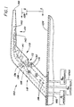
- Figure 1 is an view in side elevation of a first embodiment of the air data probe of the present invention.
- Figure 2 is a view in front elevation of the air data probe of Figure 1 taken along lines 2-2 of Figure 1.
- Figure 3 is a view in side section of a modified embodiment of the combination air data probe of the present invention.
- Figure 4 is a view in cross section of the present air data probe taken along lines 4-4 of Figure 2.
- an air data sensing probe shown generally at 100, extends from a base member 102 connected to a mounting surface 104.
- the side surfaces of the walls of strut member 106 have convex shapes in lateral cross section, which generates a well-known pressure gradient when subjected to the fluid flow represented by arrows 108 as discussed in detail below.
- a sensor inlet port 112 adjacent the leading edge 110 of the aerodynamic strut 106 admits the fluid 108 into a primary fluid cavity 114.
- the positive fluid pressure near the leading edge 110 of the probe 100 provides a first pressure differential at the leading edge 110 relative to the interior of the strut 106.
- the interior of the strut 106 fluidly couples through apertures in the side walls of the strut to an area of reduced pressure at the exterior of the lateral sides of the strut 106.
- a second pressure differential between the primary cavity 114 and the exterior of the strut 106 operates to draw the boundary layer fluid through the first group of apertures 130.
- the first pressure differential urges a portion of the fluid represented by arrows 108 into the primary fluid cavity 114 before discharge of the fluid from the probe 100 through a sensor fluid exhaust port or ports 116 fluidly coupling to an area of reduced pressure.
- the fluid inlet 112 can comprise more than one port and can be located on either lateral surface of strut 106 reasonably adjacent the leading edge 110. The location of the inlet port 112 can be determined with reference to known pressure distribution data.
- a portion of the fluid represented by arrows 108 passes through fluid inlet 112 and enters the primary cavity 114, which couples to a secondary cavity 122 extending at an intersecting angle with respect to the primary cavity.
- the secondary cavity 122 houses a temperature sensing element 120 to measure the temperature of the fluid 108.
- the longitudinal axis of the secondary cavity 122 preferably forms an obtuse angle with the downstream (rearward) extension of the longitudinal axis of primary cavity 114 at their junction.
- the longitudinal axis of the primary cavity parallels the fluid flow direction.
- the pressure gradient outside of an aerodynamic body similar to the air data probe 100 begins with positive pressure at the leading edge 110 and an area of progressively reduced pressure is present with increasing distance aft of the leading edge.
- Maximum negative pressure is near the point of maximum lateral thickness of the aerodynamic body. Since measuring total temperature requires a portion, but not all, of the fluid flow to impinge upon the temperature sensing element 120, the inlet 112 is located in an area of positive pressure and the exhaust ports 116 located in a less positive or negative pressure zone so that suitable fluid flow through probe 100 occurs.
- the one or more fluid bleed holes 116 couple the interior of a tertiary cavity 126 to the exterior of strut 100 in an area of reduced fluid pressure on the exterior of the strut compared to the fluid pressure at the inlet 112 to promote fluid flow therethrough.
- the exhaust openings 116 preferably are located near the thickest lateral dimension of the probe 100, to urge a sample core of fluid flowing through the interior cavities of the probe 100 to pass out the exhaust openings 116 due to the fluid pressure differential present between the interior cavity between the interior cavity and the exterior of the probe.
- the first group of apertures 130 are shown and fluidly couple the surfaces defining the primary cavity 114 to the lower pressure region of the exterior of strut 106 to remove an amount of a boundary layer fluid from the surfaces defining the inlet region of the primary cavity 114 on the interior of the strut.
- the first group of apertures 130 operate to withdraw boundary layer fluid from the relatively high fluid pressure present at the inlet to primary cavity 114 and expel the boundary layer fluid to an area of relatively lower fluid pressure at the lateral exterior surface of the probe 100.
- a second group of apertures 132 formed through a deflector wall member 131 bleed boundary layer fluid from the primary cavity 114 and also from the inlet region of the of the second cavity 122 adjacent the junction with the primary cavity, into a tertiary cavity 126, which is maintained at a relatively reduced pressure by bleed holes 116.
- the core sample of the fluid indicated by arrows 108 impinges upon the suitable temperature sensing element 120 disposed in the second cavity 122.
- Temperature sensing element 120 provides an output signal on line 134 for use by suitable air data processing equipment, not shown.
- Temperature sensing element 120 may comprise an electrical resistance thermometer, thermistor, optical pyrometer sensor, or other sensor as known or later adapted in the art.
- Inertial separation of entrained particles occurs when the fluid entering the primary cavity flows over the opening to the secondary cavity,which is a zone of decreased pressure, which extends over a part of the deflector member 131.
- the particles, which possess inertia, do not turn as they flow over the corner where the secondary cavity 122 and the primary cavity 114 intersect. Therefore, the entrained particles continue on a generally linear course through the primary cavity 114 and vent from the primary fluid exhaust port 118 formed in a low pressure area downstream of the entrance to the secondary cavity 122.
- the exhaust port can be at the terminal end of the primary fluid cavity 114 of the probe 100 or can be formed through the sidewall of the strut.
- Boundary layer fluid separation occurs as a result of the distributed boundary layer fluid withdrawal so that only core sample fluid impinges upon temperature sensing element 120.
- the temperature sensing element 120 generates an output signal on line 134 related to the total temperature of the flowing fluid.
- the probe 100 connects to a relatively conventional barrel-shaped pitot or pitot-static probe head 101 mounted facing the fluid flow represented by arrows 108 at the end of the strut 106 remote from the mounting surface 104.
- the pitot, pitot-static or angle of attack probe is joined to the strut 106, with few modifications being required for the implementation of the pressure sensing features which are well known in the art.
- Suitable tubes or ducting 136,138 are provided to at least one static pressure port 142 and/or one pitot pressure port 140, and suitable heating means 141 is provided to remove or avoid ice buildup.
- the tubes or ducting 136,138 lead to instrumentation shown at 140A for pitot pressure instruments and labeled Pm1 and Pm2 for the static pressure indications as shown in U.S. patent 4,730,487.
- the suitable heating elements 141 added to the outer shell of probe 100 allows all-weather operation of the probe 100.
- the heating elements 141 can be internally brazed into the strut 100 or externally brazed into grooves on the outside of strut 100 to provide a deicing capability necessary for accurate operation of probe 100 under severe icing conditions.
- a further deicing capability results from circulation of ingested fluid through various apertures 123 fluidly coupling the secondary cavity 122 to the tertiary cavity 126 so that fluid flows into the tertiary cavity 126 and circulates within the heated interior spaces forming cavity 126 of the probe before being expelled through the exhaust ports 116.
- This internal fluid circulation reduces the thermal output required from the heater 141 so that heat generated from the heater 141 is reduced, to in turn reduce the heater effect on the temperature sensing element 120.
- Heating element 141 imparts a higher temperature to the tertiary cavity 126 so that the fluid circulating within tertiary cavity 126 conducts heat to the probe walls to efficiently deice the probe 100.
- Appropriate protective shielding 120A ( Figure 3) for the sensing element 120 can be used to shield the sensing element 120 from thermal and radiation transients, as known in the art.
- Figure 3 is a modified shape air data sensor mounted on a strut section having an interior cavity arrangement identical to Figures 1, 2 and 4.
- the outer end of the strut section shown in Figure 3 curves from the strut section forwardly toward a leading end that faces upstream and which can have pitot and static ports, as shown on the barrel shaped probe of Figure 1.
Landscapes
- Physics & Mathematics (AREA)
- General Physics & Mathematics (AREA)
- Engineering & Computer Science (AREA)
- Aviation & Aerospace Engineering (AREA)
- Measuring Temperature Or Quantity Of Heat (AREA)
- Aerodynamic Tests, Hydrodynamic Tests, Wind Tunnels, And Water Tanks (AREA)
- Measuring Fluid Pressure (AREA)
Claims (13)
- Luftdatensonde (100) zum Erfassen von Parametern eines Fluids, das sich relativ zur Sonde bewegt, umfassend:eine aerodynamische Strebe (106) mit einem vorderen Rand (110) und einem hinteren Rand, wobei am vorderen Rand der Strebe mindestens eine Einlassöffnung (112) ausgebildet ist, undeinen primären Hohlraum (114), der an einem ersten Ende mit der mindestens einen Einlassöffnung in Fluidverbindung steht und mit mindestens einer Auslassöffnung (118) in Fluidverbindung steht, und weiter miteinem sekundären Fluidhohlraum (122) in der Strebe, der mit einem ersten Teil des primären Fluidhohlraums in Fluidverbindung steht und sich in seitlicher Richtung vom primären Fluidhohlraum weg erstreckt, wobei der sekundäre Fluidhohlraum mit einer Fluidabgabeöffnung (116) verbunden ist, die sich in einen Bereich geringeren Fluiddrucks öffnet;einer im sekundären Fluidhohlraum angeordneten Temperaturerfassungseinrichtung (120) zur Erfassung eines Temperaturparameters des hindurchtretenden Fluids und zur Bereitstellung eines Ausgangssignals, undeinem porösen Wandteil (132), der eine innere Oberfläche von mindestens einem Einlassteil des sekundären Fluidhohlraums angrenzend an den primären Fluidhohlraum bildet, um ein Zurückziehen von Grenzflächenfluid vom Einlassteil zu fördern.
- Luftdatensonde nach Anspruch 1, bei der ein zweiter poröser Wandteil (130) einen Teil der Strebe bildet, der das Äußere der Strebe mit inneren Oberflächen verbindet, die einen Einlassteil des primären Fluidhohlraums begrenzen, um ein Zurückziehen von Grenzflächenfluid von den inneren Oberflächen des Einlassteils des primären Fluidhohlraums zu fördern.
- Luftdatensonde nach Anspruch 1 oder Anspruch 2, bei der die Strebe einen Fußteil (102) aufweist, der Einrichtungen zum Anbringen des Fußteils an einem Luftfahrzeug (104) einschließt.
- Luftdatensonde nach Anspruch 1, bei der sich die Strebe in einer Richtung krümmt, um ein Ende (140) zu bilden, das einer Fluidströmung von einem Fußteil (102) aus nach außen zu entgegen weist.
- Luftdatensonde nach einem der vorangehenden Ansprüche, bei der eine Strahlungsabschirmung (120A) die Temperaturerfassungseinrichtung umgibt.
- Luftdatensonde nach einem der vorangehenden Ansprüche, bei der die Sonde eine Heizeinrichtung (141) in Wärmeverbindung mit der Strebe aufweist.
- Luftdatensonde nach einem der vorangehenden Ansprüche, bei der die Temperaturerfassungseinrichtung ein Platin-Widerstandselement umfasst.
- Luftdatensonde nach einem der vorangehenden Ansprüche, weiter umfassend ein langgestrecktes Rohrelement (101), das mindestens eine Druckerfassungsöffnung (140, 142) aufweist und an einem Teil des vorderen Randes der Strebe angebracht ist, sowie eine Einrichtung zum Übertragen von Drucksignalen (136, 138), die mit der mindestens einen Druckerfassungsöffnung verbunden ist.
- Luftdatensonde nach Anspruch 8, bei der die Übertragungseinrichtung eine Mehrzahl von druckempfindlichen Leitungen (136, 138) umfasst.
- Luftdatensonde nach Anspruch 9, bei der das Rohrelement eine Staudrucksonde umfasst.
- Luftdatensonde nach einem der vorangehenden Ansprüche, bei der sich die Strebe in einer Richtung auf eine Fluidströmung zu krümmt, während sie sich in einer Richtung weg von einem Fußteil (104) erstreckt, um einen Sondenrohrendteil (110) zu bilden.
- Luftdatensonde nach einem der vorangehenden Ansprüche, bei der der sekundäre Hohlraum den primären Hohlraum kreuzt und sich unter einem Winkel in Bezug zur Richtung des Fluidstroms durch den primären Hohlraum in seitlicher Richtung aus diesem erstreckt, so dass Partikel über die Öffnung des sekundären Hohlraums strömen.
- Luftdatensonde nach einem der vorangehenden Ansprüche, bei der die Strebe zwischen dem vorderen und dem hinteren Rand eine Breite aufweist, wobei die Breite groß genug ist, um in Bereichen entlang von Seiten der Strebe, umfassend den Bereich geringeren Fluiddrucks, eine Druckreduzierung zu verursachen.
Applications Claiming Priority (3)
| Application Number | Priority Date | Filing Date | Title |
|---|---|---|---|
| US12263893A | 1993-09-17 | 1993-09-17 | |
| US122638 | 1993-09-17 | ||
| PCT/US1994/010532 WO1995008122A1 (en) | 1993-09-17 | 1994-09-16 | Integral airfoil total temperature sensor |
Publications (2)
| Publication Number | Publication Date |
|---|---|
| EP0719416A1 EP0719416A1 (de) | 1996-07-03 |
| EP0719416B1 true EP0719416B1 (de) | 1999-07-28 |
Family
ID=22403901
Family Applications (1)
| Application Number | Title | Priority Date | Filing Date |
|---|---|---|---|
| EP94929234A Expired - Lifetime EP0719416B1 (de) | 1993-09-17 | 1994-09-16 | Integrierbarer tragflächenmessaufnehmer für die gesamttemperatur |
Country Status (8)
| Country | Link |
|---|---|
| US (1) | US5731507A (de) |
| EP (1) | EP0719416B1 (de) |
| JP (1) | JP2843680B2 (de) |
| CN (1) | CN1047849C (de) |
| DE (1) | DE69419763T2 (de) |
| IL (1) | IL110987A0 (de) |
| RU (1) | RU2137140C1 (de) |
| WO (1) | WO1995008122A1 (de) |
Families Citing this family (61)
| Publication number | Priority date | Publication date | Assignee | Title |
|---|---|---|---|---|
| US5601254A (en) * | 1994-10-28 | 1997-02-11 | Rosemount Aerospace Inc. | Single sided backbone strut for air data sensor |
| JP2734414B2 (ja) * | 1995-06-12 | 1998-03-30 | 助川電気工業株式会社 | 高温ガス温度測定器 |
| RU2152042C1 (ru) | 1998-05-26 | 2000-06-27 | Центральный аэрогидродинамический институт им. проф. Н.Е. Жуковского | Приемник воздушного давления (варианты) |
| US6370450B1 (en) | 1999-12-10 | 2002-04-09 | Rosemount Aerospace Inc. | Integrated total temperature probe system |
| FR2802647B1 (fr) * | 1999-12-17 | 2002-03-01 | Thomson Csf Sextant | Sonde pour aeronef |
| US6452542B1 (en) | 2001-03-02 | 2002-09-17 | Rosemount Aerospace Inc. | Integrated flight management system |
| JP3749135B2 (ja) * | 2001-03-13 | 2006-02-22 | 横河電子機器株式会社 | 温度測定装置 |
| US6591696B2 (en) * | 2001-07-12 | 2003-07-15 | Rosemount Aerospace, Inc. | Integral electric pressure probe for aircraft |
| US6543298B2 (en) * | 2001-07-13 | 2003-04-08 | Rosemount Aerospace Inc. | Method of reducing total temperature errors and multi-function probe implementing same |
| US6609825B2 (en) * | 2001-09-21 | 2003-08-26 | Rosemount Aerospace Inc. | Total air temperature probe providing improved anti-icing performance and reduced deicing heater error |
| US6827485B2 (en) * | 2002-07-16 | 2004-12-07 | Rosemount Aerospace Inc. | Fast response temperature sensor |
| US6668640B1 (en) | 2002-08-12 | 2003-12-30 | Rosemount Aerospace Inc. | Dual-channel electronic multi-function probes and methods for realizing dissimilar and independent air data outputs |
| US6892584B2 (en) * | 2002-11-19 | 2005-05-17 | Rosemount Aerospace Inc. | Fabricated pitot probe assembly |
| US6809648B1 (en) * | 2002-11-26 | 2004-10-26 | University Corporation For Atmospheric Research | Aerial sampler system |
| US6941805B2 (en) * | 2003-06-26 | 2005-09-13 | Rosemount Aerospace Inc. | Multi-function air data sensing probe having an angle of attack vane |
| US6915687B2 (en) * | 2003-07-01 | 2005-07-12 | Rosemount Aerospace Inc. | Aerodynamically shaped static pressure sensing probe |
| US7056085B2 (en) | 2004-07-09 | 2006-06-06 | General Electric Company | Methods and apparatus for sensing parameters of air flows |
| US7156552B2 (en) * | 2004-09-07 | 2007-01-02 | University Corporation For Atmospheric Research | Temperature sensor system for mobile platforms |
| US7377159B2 (en) * | 2005-08-16 | 2008-05-27 | Honeywell International Inc. | Methods and system for determining angles of attack and sideslip using flow sensors |
| USD548634S1 (en) | 2005-09-20 | 2007-08-14 | Rosemount Aerospace Inc. | Total air temperature probe |
| USD545227S1 (en) | 2005-09-20 | 2007-06-26 | Rosemount Aerospace Inc. | Total air temperature probe |
| US7357572B2 (en) * | 2005-09-20 | 2008-04-15 | Rosemount Aerospace Inc. | Total air temperature probe having improved deicing heater error performance |
| US7490510B2 (en) * | 2005-10-24 | 2009-02-17 | Ametek, Inc. | Multi-function air data sensor |
| US20100116806A1 (en) * | 2007-05-08 | 2010-05-13 | Honeywell International Inc. | Automated heating system for ports susceptible to icing |
| US7828477B2 (en) * | 2007-05-14 | 2010-11-09 | Rosemount Aerospace Inc. | Aspirated enhanced total air temperature probe |
| GB2455728A (en) | 2007-12-18 | 2009-06-24 | Weston Aerospace Ltd | Air temperature sensing on aircraft |
| US8392141B2 (en) * | 2009-11-02 | 2013-03-05 | Rosemount Aerospace Inc. | Total air temperature probe and method for reducing de-icing/anti-icing heater error |
| FR2956737B1 (fr) | 2010-02-25 | 2012-03-30 | Auxitrol Sa | Sonde brise glace pour la mesure de la temperature totale d'air |
| US8365591B2 (en) * | 2010-11-15 | 2013-02-05 | Rosemount Aerospace Inc. | Static port apparatus |
| FR2983964B1 (fr) * | 2011-12-09 | 2014-01-10 | Thales Sa | Sonde de mesure de pression totale d'un ecoulement et procede de mise en oeuvre de la sonde |
| GB201213576D0 (en) | 2012-07-31 | 2012-09-12 | Rolls Royce Plc | Total temperature probe |
| US9658117B2 (en) * | 2012-08-18 | 2017-05-23 | Rosemount Aerospace Inc. | Total air temperature probes for reducing deicing heater error |
| US9103731B2 (en) | 2012-08-20 | 2015-08-11 | Unison Industries, Llc | High temperature resistive temperature detector for exhaust gas temperature measurement |
| US9709461B2 (en) * | 2012-11-30 | 2017-07-18 | Sensata Technologies, Inc. | Method of integrating a temperature sensing element |
| US9829395B2 (en) | 2012-12-13 | 2017-11-28 | Rosemount Aerospace Inc. | Air temperature sensor arrangement for a vehicle and method of measuring air temperature |
| US9541429B2 (en) | 2014-06-02 | 2017-01-10 | University Of Kansas | Systems, methods, and devices for fluid data sensing |
| US10585109B2 (en) | 2014-06-02 | 2020-03-10 | University Of Kansas | Systems, methods, and devices for fluid data sensing |
| US9702783B2 (en) | 2014-08-01 | 2017-07-11 | Rosemount Aerospace Inc. | Air data probe with fluid intrusion sensor |
| KR101676002B1 (ko) | 2015-01-30 | 2016-11-15 | 한국표준과학연구원 | 전온도 센서 교정 장치 및 이를 이용한 전온도 센서 교정 방법 |
| US20160238456A1 (en) * | 2015-02-12 | 2016-08-18 | Rosemount Aerospace Inc. | Air temperature sensor and fabrication |
| US11209330B2 (en) | 2015-03-23 | 2021-12-28 | Rosemount Aerospace Inc. | Corrosion resistant sleeve for an air data probe |
| US10227139B2 (en) | 2015-03-23 | 2019-03-12 | Rosemount Aerospace Inc. | Heated air data probes |
| US10619506B2 (en) | 2015-04-23 | 2020-04-14 | Nuovo Pignone S.R.L. | Measuring total pressure of a fluid in a turbo machine |
| GB2541356A (en) * | 2015-06-08 | 2017-02-22 | Meggitt (Uk) Ltd | Moving-vane angle of attack probe |
| US9606137B2 (en) | 2015-06-17 | 2017-03-28 | Rosemount Aerospace Inc. | Enhancements for differential-pressure-driven fluid flows |
| CN105138014A (zh) * | 2015-09-24 | 2015-12-09 | 江西洪都航空工业集团有限责任公司 | 一种轻小型飞机航电系统构型 |
| CN107543649B (zh) * | 2016-06-26 | 2023-10-24 | 成都凯天电子股份有限公司 | 热气除冰总压受感器 |
| US10197588B2 (en) * | 2016-11-09 | 2019-02-05 | Honeywell International Inc. | Thin film heating systems for air data probes |
| US11414195B2 (en) | 2018-03-23 | 2022-08-16 | Rosemount Aerospace Inc. | Surface modified heater assembly |
| US11686577B2 (en) * | 2018-09-20 | 2023-06-27 | Raytheon Technologies Corporation | Anti-rotation method for angled face cap probe |
| US11002754B2 (en) | 2018-11-06 | 2021-05-11 | Rosemount Aerospace Inc. | Pitot probe with mandrel and pressure swaged outer shell |
| US10884014B2 (en) | 2019-03-25 | 2021-01-05 | Rosemount Aerospace Inc. | Air data probe with fully-encapsulated heater |
| US11428707B2 (en) | 2019-06-14 | 2022-08-30 | Rosemount Aerospace Inc. | Air data probe with weld sealed insert |
| CN112556728B (zh) * | 2019-09-25 | 2022-07-19 | 中国航发商用航空发动机有限责任公司 | 一种防冰传感器及具有其的发动机 |
| CN110715750B (zh) * | 2019-10-18 | 2024-11-12 | 成都凯天电子股份有限公司 | 总温传感器防冰除冰方法 |
| US11773745B2 (en) | 2020-02-28 | 2023-10-03 | Rosemount Aerospace Inc. | Pressure and temperature sensors and methods of controlling ice accretion on pressure and temperature sensors |
| US11879345B2 (en) | 2020-02-28 | 2024-01-23 | Rosemount Aerospace Inc. | Pressure and temperature sensors and methods of removing ice from pressure and temperature sensors |
| US11655726B2 (en) * | 2020-02-28 | 2023-05-23 | Rosemount Aerospace Inc. | Pressure and temperature sensors and related methods |
| AT524542B1 (de) * | 2021-02-03 | 2022-07-15 | Avl List Gmbh | Differenzdrucksensorvorrichtung zur Volumenstrombestimmung |
| US11662235B2 (en) | 2021-10-01 | 2023-05-30 | Rosemount Aerospace Inc. | Air data probe with enhanced conduction integrated heater bore and features |
| US11624637B1 (en) | 2021-10-01 | 2023-04-11 | Rosemount Aerospace Inc | Air data probe with integrated heater bore and features |
Family Cites Families (20)
| Publication number | Priority date | Publication date | Assignee | Title |
|---|---|---|---|---|
| US2488810A (en) * | 1946-05-25 | 1949-11-22 | Easterday Karl | Automatic shutter mechanism for pitot tubes |
| US2936617A (en) * | 1955-01-20 | 1960-05-17 | Task Corp | Swinvel mounted aircraft instruments |
| US2970475A (en) * | 1956-10-08 | 1961-02-07 | Rosemount Eng Co Ltd | Gas temperature probe |
| US2931227A (en) * | 1957-07-22 | 1960-04-05 | Frank D Werner | Gas temperature probe |
| US3170328A (en) * | 1961-06-13 | 1965-02-23 | Frank D Werner | Total temperature probe |
| US3512414A (en) * | 1968-05-23 | 1970-05-19 | Rosemount Eng Co Ltd | Slotted airfoil sensor housing |
| US4152938A (en) * | 1978-05-19 | 1979-05-08 | Karl Danninger | Aircraft temperature probe |
| US4615213A (en) * | 1983-12-22 | 1986-10-07 | Rosemount Inc. | Pressure sensing instrument for aircraft |
| FR2569848B1 (fr) * | 1984-09-03 | 1986-09-05 | Crouzet Badin Sa | Sonde de pression multifonction pur aeronef |
| US5018873A (en) * | 1985-04-22 | 1991-05-28 | General Electric Company | Air temperature measurement |
| US4730487A (en) * | 1985-06-04 | 1988-03-15 | Rosemount Inc. | Family of aerodynamically compensated multiple static pressure tubes |
| US4645517A (en) * | 1985-09-20 | 1987-02-24 | Rosemount Inc. | Drain manifold for air data sensor |
| US4718273A (en) * | 1985-12-31 | 1988-01-12 | The Garrett Corporation | Combination alpha, static and total pressure probe |
| US4677858A (en) * | 1986-03-13 | 1987-07-07 | Ohnhaus Buford U | Double-acting pitot tube |
| GB2203251B (en) * | 1987-03-25 | 1991-08-07 | Rosemount Ltd | Air data measurement apparatus |
| US4765751A (en) * | 1987-06-29 | 1988-08-23 | United Technologies Corporation | Temperature and pressure probe |
| US5025661A (en) * | 1989-12-11 | 1991-06-25 | Allied-Signal Inc. | Combination air data probe |
| FR2665539B1 (fr) * | 1990-08-03 | 1992-11-27 | Sextant Avionique | Sonde d'aeronef pour la mesure des parametres aerodynamiques de l'ecoulement ambiant. |
| US5076103A (en) * | 1990-08-31 | 1991-12-31 | The United States Of America As Represented By The Administrator Of The National Aeronautics And Space Administration | Water cooled static pressure probe |
| JP2954349B2 (ja) * | 1991-03-22 | 1999-09-27 | ローズマウント インコーポレイテッド | 連続曲面支柱で支持されたセンサ |
-
1994
- 1994-05-27 US US08/250,342 patent/US5731507A/en not_active Expired - Lifetime
- 1994-09-16 JP JP7509392A patent/JP2843680B2/ja not_active Expired - Fee Related
- 1994-09-16 WO PCT/US1994/010532 patent/WO1995008122A1/en not_active Ceased
- 1994-09-16 RU RU96107256A patent/RU2137140C1/ru not_active IP Right Cessation
- 1994-09-16 EP EP94929234A patent/EP0719416B1/de not_active Expired - Lifetime
- 1994-09-16 DE DE69419763T patent/DE69419763T2/de not_active Expired - Lifetime
- 1994-09-16 CN CN94193422A patent/CN1047849C/zh not_active Expired - Lifetime
- 1994-09-18 IL IL11098794A patent/IL110987A0/xx unknown
Also Published As
| Publication number | Publication date |
|---|---|
| RU2137140C1 (ru) | 1999-09-10 |
| CN1131464A (zh) | 1996-09-18 |
| JP2843680B2 (ja) | 1999-01-06 |
| DE69419763T2 (de) | 2000-04-06 |
| WO1995008122A1 (en) | 1995-03-23 |
| CN1047849C (zh) | 1999-12-29 |
| IL110987A0 (en) | 1994-11-28 |
| JPH09504102A (ja) | 1997-04-22 |
| EP0719416A1 (de) | 1996-07-03 |
| DE69419763D1 (de) | 1999-09-02 |
| US5731507A (en) | 1998-03-24 |
Similar Documents
| Publication | Publication Date | Title |
|---|---|---|
| EP0719416B1 (de) | Integrierbarer tragflächenmessaufnehmer für die gesamttemperatur | |
| US5628565A (en) | Multifunctional air data sensing probes | |
| US8104955B2 (en) | Aspirated enhanced total air temperature probe | |
| US6840672B2 (en) | Total air temperature probe providing improved anti-icing performance and reduced deicing heater error | |
| JP4422907B2 (ja) | 航空機用空気温度センサ一体組込プローブ | |
| EP3399291B1 (de) | Vereisungswiderstandgesamttemperatursonde mit integriertem ausstosser | |
| EP1491900B1 (de) | Multifunktions-Luftdatensensor mit Schwenkflügel-Anstellwinkelsensor | |
| EP1764593B1 (de) | Gesamtlufttemperatursonde mit verbessertem Enteisungsheizelementfehlerverhalten | |
| US7416329B2 (en) | Thermal icing conditions detector | |
| EP3346246B1 (de) | Vereisungsbeständige gesamtlufttemperatursonde mit luftstrahlen | |
| EP3205582B1 (de) | Gesamtlufttemperatursonde mit effizientem teilchendurchgang | |
| US6915687B2 (en) | Aerodynamically shaped static pressure sensing probe | |
| JP2002500365A (ja) | 回転するブレード用のブレード取付型全圧プローブ | |
| EP4458679A1 (de) | Luftstrommodifizierungsvorrichtung | |
| GB2629594A (en) | Airflow modifying device | |
| EP4705185A1 (de) | Luftstrommodifizierungsvorrichtung |
Legal Events
| Date | Code | Title | Description |
|---|---|---|---|
| PUAI | Public reference made under article 153(3) epc to a published international application that has entered the european phase |
Free format text: ORIGINAL CODE: 0009012 |
|
| 17P | Request for examination filed |
Effective date: 19960406 |
|
| AK | Designated contracting states |
Kind code of ref document: A1 Designated state(s): DE FR GB |
|
| 17Q | First examination report despatched |
Effective date: 19970514 |
|
| GRAG | Despatch of communication of intention to grant |
Free format text: ORIGINAL CODE: EPIDOS AGRA |
|
| GRAG | Despatch of communication of intention to grant |
Free format text: ORIGINAL CODE: EPIDOS AGRA |
|
| GRAH | Despatch of communication of intention to grant a patent |
Free format text: ORIGINAL CODE: EPIDOS IGRA |
|
| GRAH | Despatch of communication of intention to grant a patent |
Free format text: ORIGINAL CODE: EPIDOS IGRA |
|
| GRAA | (expected) grant |
Free format text: ORIGINAL CODE: 0009210 |
|
| AK | Designated contracting states |
Kind code of ref document: B1 Designated state(s): DE FR GB |
|
| REF | Corresponds to: |
Ref document number: 69419763 Country of ref document: DE Date of ref document: 19990902 |
|
| ET | Fr: translation filed | ||
| PLBE | No opposition filed within time limit |
Free format text: ORIGINAL CODE: 0009261 |
|
| STAA | Information on the status of an ep patent application or granted ep patent |
Free format text: STATUS: NO OPPOSITION FILED WITHIN TIME LIMIT |
|
| 26N | No opposition filed | ||
| REG | Reference to a national code |
Ref country code: GB Ref legal event code: IF02 |
|
| PGFP | Annual fee paid to national office [announced via postgrant information from national office to epo] |
Ref country code: DE Payment date: 20130911 Year of fee payment: 20 |
|
| PGFP | Annual fee paid to national office [announced via postgrant information from national office to epo] |
Ref country code: GB Payment date: 20130911 Year of fee payment: 20 Ref country code: FR Payment date: 20130910 Year of fee payment: 20 |
|
| REG | Reference to a national code |
Ref country code: DE Ref legal event code: R071 Ref document number: 69419763 Country of ref document: DE |
|
| REG | Reference to a national code |
Ref country code: GB Ref legal event code: PE20 Expiry date: 20140915 |
|
| PG25 | Lapsed in a contracting state [announced via postgrant information from national office to epo] |
Ref country code: DE Free format text: LAPSE BECAUSE OF EXPIRATION OF PROTECTION Effective date: 20140917 |
|
| PG25 | Lapsed in a contracting state [announced via postgrant information from national office to epo] |
Ref country code: GB Free format text: LAPSE BECAUSE OF EXPIRATION OF PROTECTION Effective date: 20140915 |