EP0719504A1 - Anpassstück für eine Stanzpresse - Google Patents
Anpassstück für eine Stanzpresse Download PDFInfo
- Publication number
- EP0719504A1 EP0719504A1 EP94309440A EP94309440A EP0719504A1 EP 0719504 A1 EP0719504 A1 EP 0719504A1 EP 94309440 A EP94309440 A EP 94309440A EP 94309440 A EP94309440 A EP 94309440A EP 0719504 A1 EP0719504 A1 EP 0719504A1
- Authority
- EP
- European Patent Office
- Prior art keywords
- chuck
- machine
- spindle
- eyelet
- holder
- Prior art date
- Legal status (The legal status is an assumption and is not a legal conclusion. Google has not performed a legal analysis and makes no representation as to the accuracy of the status listed.)
- Granted
Links
- 239000000463 material Substances 0.000 claims description 13
- 239000002184 metal Substances 0.000 claims description 3
- 239000011111 cardboard Substances 0.000 claims description 2
- 238000000605 extraction Methods 0.000 claims description 2
- 239000010985 leather Substances 0.000 claims description 2
- 239000004033 plastic Substances 0.000 claims description 2
- 239000007787 solid Substances 0.000 claims description 2
- 239000004753 textile Substances 0.000 claims description 2
- 238000006243 chemical reaction Methods 0.000 description 4
- 238000004080 punching Methods 0.000 description 4
- 210000000080 chela (arthropods) Anatomy 0.000 description 2
- 238000010276 construction Methods 0.000 description 2
- 238000000034 method Methods 0.000 description 1
- 230000000284 resting effect Effects 0.000 description 1
Images
Classifications
-
- A—HUMAN NECESSITIES
- A41—WEARING APPAREL
- A41H—APPLIANCES OR METHODS FOR MAKING CLOTHES, e.g. FOR DRESS-MAKING OR FOR TAILORING, NOT OTHERWISE PROVIDED FOR
- A41H37/00—Machines, appliances or methods for setting fastener-elements on garments
- A41H37/02—Setting hooks or eyes
-
- A—HUMAN NECESSITIES
- A43—FOOTWEAR
- A43D—MACHINES, TOOLS, EQUIPMENT OR METHODS FOR MANUFACTURING OR REPAIRING FOOTWEAR
- A43D100/00—Setting or removing eyelets, buttons, lacing-hooks, or elastic gussets in shoes
- A43D100/02—Punching and eyelet-setting machines or tools
Definitions
- the present invention concerns a group of adaptor parts for a machine-punch suited to applying minute connecting pieces, especially eyelets, rivets and press-studs onto objects of textile, plastic, metal, leather, cardboard and similar materials, to be used in various and conventional manners.
- the invention is suited for converting a riveting machine into an eyelet punching machine.
- Machines for the application of these small pieces, generally made of metal, are divided into two main groups:
- - chuck - defines the shaft that, having parts suited to operating on eyelets, rivets, press studs and similar, at its lower end, is provided with a down and upstroke movement.
- a spindle that extends below a bushing set on the bottom of the chuck feeds one eyelet after the other from a convenient distributor; then, the spindle retracts into the bushing at the bottom of the chuck at the moment in which the eyelet is applied; the spindle must extend during the final part of the upstroke movement of the chuck; to this purpose, a device to extract the spindle from the eyelet comprising a cylinder sliding within the chuck and fixed to the body of the machine by means of a pin that transversally crosses the chuck along which a slot is set with length slightly more than the chuck's stroke (generally 50-60 mm). Perforating eyelet punches are called this way because in them the spindle also works in perforating the material onto which the eyelet must be applied.
- each rivet is fed from an appropriate box by means of a pincer-punch unit that accompanies it until its application.
- the purpose of the present invention is to greatly simplify the conversion of one of these machine-punches, especially of a riveting press into an eyelet punch or of an eyelet punch into a riveting press, in order that the conversion may be conducted by not specially expert personnel.
- the chuck of a riveting press is the more simple of the chucks of the two different types of machine in as much as the job of feeding and then applying the rivet is performed by a pincer bearing a punch screwed onto the bottom end of the chuck; it is therefore understood that the device invented is especially suited to being applied on a riveting machine.
- the group invented comprises a main part that can be screwed into the threaded cavity existing in the bottom end of the chuck of said machine-punch and bears means to feed and apply an eyelet and means for extracting the spindle from the eyelet applied, such means comprising: a tool-holder with its upper end that can be screwed into said threaded cavity in the chuck, two opposite longitudinal slots made in its lateral walls and a chamber in which an extractor cylinder slides and transversally crossed by a pin each end of which slides along said slots and held in a sleeve sliding along the tool-holder, the purpose of the sleeve being that of resting against a fixed or adjustable part of the machine-punch at the end of upstroke of the chuck, in order to extract the spindle from the eyelet.
- a part of the group invented, conventionally defined as secondary, that operates to perforate the material to which the eyelet is applied, will be specified below with reference to figures 3 and 4.
- the invention may also be realized for use on a pre-existing machine, given that the geometries of the parts to be connected are compatible.
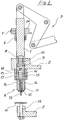
- Figure 1 shows part of a riveting press onto which the main part of the device invented to convert the riveting press into a simple eyelet punch, is fitted, that is an eyelet punch that does not previously perforate the material onto which the eyelet must be applied;
- a chuck 1 is conventionally fitted to a fixed part 2 of the machine in order to perform the necessary upstroke and downstroke movements under control of a leverage 3 run by a motor means that is not shown;
- a sleeve 4 is fixed that bears a roller 5 laterally that acts on a rectilinear cam 6 (roller 5 and cam 6 are only visible in Fig.
- the chuck 1 has a threaded cavity 8 in its bottom end into which the invented device is screwed, for the application of eyelets, instead of a conventional pincer and stud for the application of rivets;
- the device invented comprises: a tool-holder 9 with threaded top 10 screwed in said cavity 8 and with lower bore 11 bearing bushing 12 with the purpose of acting as a guide for a spindle 13 fixed into the tool-holder by means of two opposite transversal screws 14 that work by friction against the walls of the spindle; two longitudinal slots 15 diametrically opposite in the lateral walls of the tool-holder; an extractor cylinder 16 sliding within a chamber 9A of the tool-holder and connected, by means of a transversal pin 17 having its ends sliding within the two slots, to a sleeve 18 sliding along the tool-holder.
- the figure also shows: a conventional counterpoint 19 under the device, a piece of material M between the tip of the spindle 13 and the counterpoint 19 and a body 2A of the machine that is moved parallel to the chuck and fixed into the appropriate position by means of screw V to check the upstroke of the same chuck.
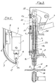
- Fig. 2 shows the conventional eyelet distributor 7 fitted on the machine next to the chuck 1 and from which the spindle 13 conventionally takes an eyelet O at each cycle; the figure also shows the roller 5 rotating on sleeve 4 solid with the chuck, cam 6 fixed to distributor 7, tool-holder 9 and spindle 13.
- the unit described above works as follows: during the descending stage of the chuck, the point of spindle 13 hooks an eyelet O and firmly grips it thanks to the action of friction screws 14; then, roller 5 acts on cam 6 to laterally push away distributor 7 in order to avoid that the latter be hit by the descending tool-holder 9; further, the point of spindle 13 presses against material M and spindle 13 begins to slide along friction screws 14 thus retracting into bushing 12 that begins to press upon the head of the eyelet causing its punching against counterpoint 19; after this, the chuck ascends with spindle 13 completely retracted into bushing 12, in the last part of the upstroke the sleeve 18 is stopped by fixed part 2 of the machine so that the spindle is extracted ready for punching the next eyelet.
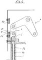
- Figure 3 shows part of a conventional riveting press onto which the main part and the secondary part of the group invented have been applied to convert the riveting press into a perforating eyelet punch;
- a chuck 1 with a cavity, conventionally set to receive the parts relative to the perforating function, is fitted to a fixed part 2 of the machine and externally, as for the chuck described in Fig. 1, is fitted a sleeve 4 laterally bearing a rotating roller 5 that acts upon cam 6 to push away distributor 7; the sleeve 4 and body 2A that can be moved parallel to the chuck perform the functions already described with reference to Fig.
Landscapes
- Engineering & Computer Science (AREA)
- Textile Engineering (AREA)
- Perforating, Stamping-Out Or Severing By Means Other Than Cutting (AREA)
- Punching Or Piercing (AREA)
- Mounting, Exchange, And Manufacturing Of Dies (AREA)
- Insertion Pins And Rivets (AREA)
Priority Applications (4)
| Application Number | Priority Date | Filing Date | Title |
|---|---|---|---|
| ES94309440T ES2138651T3 (es) | 1994-12-16 | 1994-12-16 | Piezas adaptadoras para maquina punzonadora. |
| DE69420571T DE69420571T2 (de) | 1994-12-16 | 1994-12-16 | Anpassstück für eine Stanzpresse |
| EP94309440A EP0719504B1 (de) | 1994-12-16 | 1994-12-16 | Anpassstück für eine Stanzpresse |
| AT94309440T ATE184163T1 (de) | 1994-12-16 | 1994-12-16 | Anpassstück für eine stanzpresse |
Applications Claiming Priority (1)
| Application Number | Priority Date | Filing Date | Title |
|---|---|---|---|
| EP94309440A EP0719504B1 (de) | 1994-12-16 | 1994-12-16 | Anpassstück für eine Stanzpresse |
Publications (2)
| Publication Number | Publication Date |
|---|---|
| EP0719504A1 true EP0719504A1 (de) | 1996-07-03 |
| EP0719504B1 EP0719504B1 (de) | 1999-09-08 |
Family
ID=8217950
Family Applications (1)
| Application Number | Title | Priority Date | Filing Date |
|---|---|---|---|
| EP94309440A Expired - Lifetime EP0719504B1 (de) | 1994-12-16 | 1994-12-16 | Anpassstück für eine Stanzpresse |
Country Status (4)
| Country | Link |
|---|---|
| EP (1) | EP0719504B1 (de) |
| AT (1) | ATE184163T1 (de) |
| DE (1) | DE69420571T2 (de) |
| ES (1) | ES2138651T3 (de) |
Cited By (3)
| Publication number | Priority date | Publication date | Assignee | Title |
|---|---|---|---|---|
| EP0983732A3 (de) * | 1998-09-02 | 2000-06-07 | Franz Miederhoff oHG | Vorrichtung zum Einsetzen von mittels eines Nietverbundes zusammengehaltenen Teilen, etwa von Ösen in eine Textil- oder Kunststoffbahn |
| CN109171118A (zh) * | 2018-09-20 | 2019-01-11 | 东莞市北扬工业设计有限公司 | 一种鞋子上鞋眼的铆压机构 |
| CN111227405A (zh) * | 2020-03-24 | 2020-06-05 | 杭州汉辰服饰有限公司 | 一种基于往复运动保持等距且节约能源的自动钉扣装置 |
Citations (4)
| Publication number | Priority date | Publication date | Assignee | Title |
|---|---|---|---|---|
| US1487731A (en) * | 1922-09-11 | 1924-03-25 | Said Enna | Eyelet-setting machine |
| FR2356386A1 (fr) * | 1976-07-01 | 1978-01-27 | Usm Corp | Machine a poser des oeillets |
| US4596349A (en) * | 1985-05-02 | 1986-06-24 | William Prym-Werke Kg | Machine for applying articles of hardware to textile materials and the like |
| EP0212502A2 (de) * | 1985-08-16 | 1987-03-04 | Yoshida Kogyo K.K. | Maschine zum Ansetzen von Befestigungselementen mit einer Sicherheitsvorrichtung |
-
1994
- 1994-12-16 AT AT94309440T patent/ATE184163T1/de not_active IP Right Cessation
- 1994-12-16 EP EP94309440A patent/EP0719504B1/de not_active Expired - Lifetime
- 1994-12-16 ES ES94309440T patent/ES2138651T3/es not_active Expired - Lifetime
- 1994-12-16 DE DE69420571T patent/DE69420571T2/de not_active Expired - Lifetime
Patent Citations (4)
| Publication number | Priority date | Publication date | Assignee | Title |
|---|---|---|---|---|
| US1487731A (en) * | 1922-09-11 | 1924-03-25 | Said Enna | Eyelet-setting machine |
| FR2356386A1 (fr) * | 1976-07-01 | 1978-01-27 | Usm Corp | Machine a poser des oeillets |
| US4596349A (en) * | 1985-05-02 | 1986-06-24 | William Prym-Werke Kg | Machine for applying articles of hardware to textile materials and the like |
| EP0212502A2 (de) * | 1985-08-16 | 1987-03-04 | Yoshida Kogyo K.K. | Maschine zum Ansetzen von Befestigungselementen mit einer Sicherheitsvorrichtung |
Cited By (5)
| Publication number | Priority date | Publication date | Assignee | Title |
|---|---|---|---|---|
| EP0983732A3 (de) * | 1998-09-02 | 2000-06-07 | Franz Miederhoff oHG | Vorrichtung zum Einsetzen von mittels eines Nietverbundes zusammengehaltenen Teilen, etwa von Ösen in eine Textil- oder Kunststoffbahn |
| CN109171118A (zh) * | 2018-09-20 | 2019-01-11 | 东莞市北扬工业设计有限公司 | 一种鞋子上鞋眼的铆压机构 |
| CN109171118B (zh) * | 2018-09-20 | 2020-12-04 | 苏州创力波科技有限公司 | 一种鞋子上鞋眼的铆压机构 |
| CN111227405A (zh) * | 2020-03-24 | 2020-06-05 | 杭州汉辰服饰有限公司 | 一种基于往复运动保持等距且节约能源的自动钉扣装置 |
| CN111227405B (zh) * | 2020-03-24 | 2021-12-24 | 临沂边锋自动化设备有限公司 | 一种基于往复运动保持等距且节约能源的自动钉扣装置 |
Also Published As
| Publication number | Publication date |
|---|---|
| DE69420571D1 (de) | 1999-10-14 |
| ATE184163T1 (de) | 1999-09-15 |
| ES2138651T3 (es) | 2000-01-16 |
| EP0719504B1 (de) | 1999-09-08 |
| DE69420571T2 (de) | 2000-03-30 |
Similar Documents
| Publication | Publication Date | Title |
|---|---|---|
| EP0172171B1 (de) | Zuführvorrichtungen für befestigungselemente mit kopf | |
| US4031787A (en) | Punch and stripper assembly | |
| DE69011412T2 (de) | Mehrfachwerkzeughalter für Stanzstempel. | |
| EP2669024B1 (de) | Werkzeugmaschine und Verfahren zum Ausschieben eines Werkstückteils | |
| EP0237800B1 (de) | Abkantpresse zum Gesenkbiegen von insbesondere Blechen | |
| US3540339A (en) | Stripper-holddown assembly for punch presses | |
| GB1068961A (en) | Improvements in or relating to a pulling head device for the stem of fasteners | |
| US3848496A (en) | Die and spring assemblies having particular application to stripper plates | |
| US4552050A (en) | Die, platen and joining means for attaching said die to said platen | |
| EP0719504B1 (de) | Anpassstück für eine Stanzpresse | |
| CA2016723C (en) | Punch holder with a stripper arrangement | |
| US4516448A (en) | Punch and ram assembly for punch press | |
| US4516449A (en) | Tool holder with work release mechanism | |
| US3712163A (en) | Shuttle press | |
| US2893488A (en) | Perforating implement having means to align the punch and die | |
| US2468998A (en) | Retainer-stripper unit for punch presses | |
| CN211803352U (zh) | 一种汽车前后门内板冲孔设备导引机构 | |
| DE704344C (de) | Selbsttaetige Bohr- und Nietmaschine | |
| EP1307316A1 (de) | Funktionsträgeranordnung, werkzeug zur anwendung mit der funktionsträgeranordnung sowie verfahren zum einsetzen der funktionsträgeranordnung in ein bauteil | |
| US2352429A (en) | Tool for upsetting die heads | |
| EP0648618B1 (de) | Münzprägepresse zum Prägen oder Lochen | |
| US2805717A (en) | Self-contained perforating implement | |
| US2779038A (en) | Apparatus for cutting and inserting resilient plugs in threaded fastening members | |
| US4052871A (en) | Stock-piercing punch mechanism | |
| CN210254956U (zh) | 一种压簧片机构 |
Legal Events
| Date | Code | Title | Description |
|---|---|---|---|
| PUAI | Public reference made under article 153(3) epc to a published international application that has entered the european phase |
Free format text: ORIGINAL CODE: 0009012 |
|
| AK | Designated contracting states |
Kind code of ref document: A1 Designated state(s): AT BE CH DE DK ES FR GB GR IE IT LI LU MC NL PT SE |
|
| 17P | Request for examination filed |
Effective date: 19961212 |
|
| 17Q | First examination report despatched |
Effective date: 19980915 |
|
| GRAG | Despatch of communication of intention to grant |
Free format text: ORIGINAL CODE: EPIDOS AGRA |
|
| GRAG | Despatch of communication of intention to grant |
Free format text: ORIGINAL CODE: EPIDOS AGRA |
|
| GRAH | Despatch of communication of intention to grant a patent |
Free format text: ORIGINAL CODE: EPIDOS IGRA |
|
| GRAH | Despatch of communication of intention to grant a patent |
Free format text: ORIGINAL CODE: EPIDOS IGRA |
|
| GRAA | (expected) grant |
Free format text: ORIGINAL CODE: 0009210 |
|
| AK | Designated contracting states |
Kind code of ref document: B1 Designated state(s): AT BE CH DE DK ES FR GB GR IE IT LI LU MC NL PT SE |
|
| PG25 | Lapsed in a contracting state [announced via postgrant information from national office to epo] |
Ref country code: SE Free format text: THE PATENT HAS BEEN ANNULLED BY A DECISION OF A NATIONAL AUTHORITY Effective date: 19990908 Ref country code: NL Free format text: LAPSE BECAUSE OF FAILURE TO SUBMIT A TRANSLATION OF THE DESCRIPTION OR TO PAY THE FEE WITHIN THE PRESCRIBED TIME-LIMIT Effective date: 19990908 Ref country code: LI Free format text: LAPSE BECAUSE OF FAILURE TO SUBMIT A TRANSLATION OF THE DESCRIPTION OR TO PAY THE FEE WITHIN THE PRESCRIBED TIME-LIMIT Effective date: 19990908 Ref country code: GR Free format text: LAPSE BECAUSE OF NON-PAYMENT OF DUE FEES Effective date: 19990908 Ref country code: CH Free format text: LAPSE BECAUSE OF FAILURE TO SUBMIT A TRANSLATION OF THE DESCRIPTION OR TO PAY THE FEE WITHIN THE PRESCRIBED TIME-LIMIT Effective date: 19990908 Ref country code: BE Free format text: LAPSE BECAUSE OF FAILURE TO SUBMIT A TRANSLATION OF THE DESCRIPTION OR TO PAY THE FEE WITHIN THE PRESCRIBED TIME-LIMIT Effective date: 19990908 Ref country code: AT Free format text: LAPSE BECAUSE OF FAILURE TO SUBMIT A TRANSLATION OF THE DESCRIPTION OR TO PAY THE FEE WITHIN THE PRESCRIBED TIME-LIMIT Effective date: 19990908 |
|
| REF | Corresponds to: |
Ref document number: 184163 Country of ref document: AT Date of ref document: 19990915 Kind code of ref document: T |
|
| REG | Reference to a national code |
Ref country code: CH Ref legal event code: EP |
|
| REF | Corresponds to: |
Ref document number: 69420571 Country of ref document: DE Date of ref document: 19991014 |
|
| REG | Reference to a national code |
Ref country code: IE Ref legal event code: FG4D |
|
| ITF | It: translation for a ep patent filed | ||
| PG25 | Lapsed in a contracting state [announced via postgrant information from national office to epo] |
Ref country code: DK Free format text: LAPSE BECAUSE OF FAILURE TO SUBMIT A TRANSLATION OF THE DESCRIPTION OR TO PAY THE FEE WITHIN THE PRESCRIBED TIME-LIMIT Effective date: 19991208 |
|
| PG25 | Lapsed in a contracting state [announced via postgrant information from national office to epo] |
Ref country code: PT Free format text: LAPSE BECAUSE OF FAILURE TO SUBMIT A TRANSLATION OF THE DESCRIPTION OR TO PAY THE FEE WITHIN THE PRESCRIBED TIME-LIMIT Effective date: 19991209 |
|
| PG25 | Lapsed in a contracting state [announced via postgrant information from national office to epo] |
Ref country code: LU Free format text: LAPSE BECAUSE OF NON-PAYMENT OF DUE FEES Effective date: 19991216 Ref country code: IE Free format text: LAPSE BECAUSE OF NON-PAYMENT OF DUE FEES Effective date: 19991216 |
|
| ET | Fr: translation filed | ||
| REG | Reference to a national code |
Ref country code: ES Ref legal event code: FG2A Ref document number: 2138651 Country of ref document: ES Kind code of ref document: T3 |
|
| NLV1 | Nl: lapsed or annulled due to failure to fulfill the requirements of art. 29p and 29m of the patents act | ||
| REG | Reference to a national code |
Ref country code: CH Ref legal event code: PL |
|
| PG25 | Lapsed in a contracting state [announced via postgrant information from national office to epo] |
Ref country code: MC Free format text: LAPSE BECAUSE OF NON-PAYMENT OF DUE FEES Effective date: 20000630 |
|
| PLBE | No opposition filed within time limit |
Free format text: ORIGINAL CODE: 0009261 |
|
| STAA | Information on the status of an ep patent application or granted ep patent |
Free format text: STATUS: NO OPPOSITION FILED WITHIN TIME LIMIT |
|
| 26N | No opposition filed | ||
| REG | Reference to a national code |
Ref country code: IE Ref legal event code: MM4A |
|
| REG | Reference to a national code |
Ref country code: GB Ref legal event code: IF02 |
|
| PGFP | Annual fee paid to national office [announced via postgrant information from national office to epo] |
Ref country code: ES Payment date: 20091222 Year of fee payment: 16 |
|
| PGFP | Annual fee paid to national office [announced via postgrant information from national office to epo] |
Ref country code: IT Payment date: 20091222 Year of fee payment: 16 Ref country code: GB Payment date: 20091126 Year of fee payment: 16 Ref country code: FR Payment date: 20100108 Year of fee payment: 16 |
|
| PGFP | Annual fee paid to national office [announced via postgrant information from national office to epo] |
Ref country code: DE Payment date: 20091222 Year of fee payment: 16 |
|
| GBPC | Gb: european patent ceased through non-payment of renewal fee |
Effective date: 20101216 |
|
| REG | Reference to a national code |
Ref country code: FR Ref legal event code: ST Effective date: 20110831 |
|
| PG25 | Lapsed in a contracting state [announced via postgrant information from national office to epo] |
Ref country code: FR Free format text: LAPSE BECAUSE OF NON-PAYMENT OF DUE FEES Effective date: 20110103 |
|
| REG | Reference to a national code |
Ref country code: DE Ref legal event code: R119 Ref document number: 69420571 Country of ref document: DE Effective date: 20110701 |
|
| PG25 | Lapsed in a contracting state [announced via postgrant information from national office to epo] |
Ref country code: GB Free format text: LAPSE BECAUSE OF NON-PAYMENT OF DUE FEES Effective date: 20101216 Ref country code: DE Free format text: LAPSE BECAUSE OF NON-PAYMENT OF DUE FEES Effective date: 20110701 |
|
| PG25 | Lapsed in a contracting state [announced via postgrant information from national office to epo] |
Ref country code: IT Free format text: LAPSE BECAUSE OF NON-PAYMENT OF DUE FEES Effective date: 20101216 |
|
| REG | Reference to a national code |
Ref country code: ES Ref legal event code: FD2A Effective date: 20120206 |
|
| PG25 | Lapsed in a contracting state [announced via postgrant information from national office to epo] |
Ref country code: ES Free format text: LAPSE BECAUSE OF NON-PAYMENT OF DUE FEES Effective date: 20101217 |