EP0719600A1 - Une unité de laminage pour laminer des barres ou des corps tubulaires - Google Patents
Une unité de laminage pour laminer des barres ou des corps tubulaires Download PDFInfo
- Publication number
- EP0719600A1 EP0719600A1 EP95203118A EP95203118A EP0719600A1 EP 0719600 A1 EP0719600 A1 EP 0719600A1 EP 95203118 A EP95203118 A EP 95203118A EP 95203118 A EP95203118 A EP 95203118A EP 0719600 A1 EP0719600 A1 EP 0719600A1
- Authority
- EP
- European Patent Office
- Prior art keywords
- rolling
- rolls
- unit
- axis
- roll
- Prior art date
- Legal status (The legal status is an assumption and is not a legal conclusion. Google has not performed a legal analysis and makes no representation as to the accuracy of the status listed.)
- Granted
Links
- 238000005096 rolling process Methods 0.000 title claims abstract description 116
- 239000000969 carrier Substances 0.000 claims description 3
- 238000000034 method Methods 0.000 abstract description 2
- 230000010355 oscillation Effects 0.000 abstract description 2
- 230000008569 process Effects 0.000 abstract description 2
- 230000008901 benefit Effects 0.000 description 6
- 238000010276 construction Methods 0.000 description 3
- XEEYBQQBJWHFJM-UHFFFAOYSA-N Iron Chemical compound [Fe] XEEYBQQBJWHFJM-UHFFFAOYSA-N 0.000 description 2
- 238000012423 maintenance Methods 0.000 description 2
- 238000004519 manufacturing process Methods 0.000 description 2
- 229910000831 Steel Inorganic materials 0.000 description 1
- 230000009471 action Effects 0.000 description 1
- 230000004075 alteration Effects 0.000 description 1
- 238000012937 correction Methods 0.000 description 1
- 230000003247 decreasing effect Effects 0.000 description 1
- 238000013461 design Methods 0.000 description 1
- 238000006073 displacement reaction Methods 0.000 description 1
- 230000000694 effects Effects 0.000 description 1
- 229910052742 iron Inorganic materials 0.000 description 1
- 238000012986 modification Methods 0.000 description 1
- 230000004048 modification Effects 0.000 description 1
- 230000003534 oscillatory effect Effects 0.000 description 1
- 238000012545 processing Methods 0.000 description 1
- 230000000284 resting effect Effects 0.000 description 1
- 239000011265 semifinished product Substances 0.000 description 1
- 239000010959 steel Substances 0.000 description 1
- 238000011144 upstream manufacturing Methods 0.000 description 1
Images


Classifications
-
- B—PERFORMING OPERATIONS; TRANSPORTING
- B21—MECHANICAL METAL-WORKING WITHOUT ESSENTIALLY REMOVING MATERIAL; PUNCHING METAL
- B21B—ROLLING OF METAL
- B21B1/00—Metal-rolling methods or mills for making semi-finished products of solid or profiled cross-section; Sequence of operations in milling trains; Layout of rolling-mill plant, e.g. grouping of stands; Succession of passes or of sectional pass alternations
- B21B1/16—Metal-rolling methods or mills for making semi-finished products of solid or profiled cross-section; Sequence of operations in milling trains; Layout of rolling-mill plant, e.g. grouping of stands; Succession of passes or of sectional pass alternations for rolling wire rods, bars, merchant bars, rounds wire or material of like small cross-section
- B21B1/18—Metal-rolling methods or mills for making semi-finished products of solid or profiled cross-section; Sequence of operations in milling trains; Layout of rolling-mill plant, e.g. grouping of stands; Succession of passes or of sectional pass alternations for rolling wire rods, bars, merchant bars, rounds wire or material of like small cross-section in a continuous process
-
- B—PERFORMING OPERATIONS; TRANSPORTING
- B21—MECHANICAL METAL-WORKING WITHOUT ESSENTIALLY REMOVING MATERIAL; PUNCHING METAL
- B21B—ROLLING OF METAL
- B21B13/00—Metal-rolling stands, i.e. an assembly composed of a stand frame, rolls, and accessories
- B21B13/08—Metal-rolling stands, i.e. an assembly composed of a stand frame, rolls, and accessories with differently-directed roll axes, e.g. for the so-called "universal" rolling process
- B21B13/10—Metal-rolling stands, i.e. an assembly composed of a stand frame, rolls, and accessories with differently-directed roll axes, e.g. for the so-called "universal" rolling process all axes being arranged in one plane
- B21B13/103—Metal-rolling stands, i.e. an assembly composed of a stand frame, rolls, and accessories with differently-directed roll axes, e.g. for the so-called "universal" rolling process all axes being arranged in one plane for rolling bars, rods or wire
-
- B—PERFORMING OPERATIONS; TRANSPORTING
- B21—MECHANICAL METAL-WORKING WITHOUT ESSENTIALLY REMOVING MATERIAL; PUNCHING METAL
- B21B—ROLLING OF METAL
- B21B17/00—Tube-rolling by rollers of which the axes are arranged essentially perpendicular to the axis of the work, e.g. "axial" tube-rolling
- B21B17/02—Tube-rolling by rollers of which the axes are arranged essentially perpendicular to the axis of the work, e.g. "axial" tube-rolling with mandrel, i.e. the mandrel rod contacts the rolled tube over the rod length
- B21B17/04—Tube-rolling by rollers of which the axes are arranged essentially perpendicular to the axis of the work, e.g. "axial" tube-rolling with mandrel, i.e. the mandrel rod contacts the rolled tube over the rod length in a continuous process
-
- B—PERFORMING OPERATIONS; TRANSPORTING
- B21—MECHANICAL METAL-WORKING WITHOUT ESSENTIALLY REMOVING MATERIAL; PUNCHING METAL
- B21B—ROLLING OF METAL
- B21B17/00—Tube-rolling by rollers of which the axes are arranged essentially perpendicular to the axis of the work, e.g. "axial" tube-rolling
- B21B17/14—Tube-rolling by rollers of which the axes are arranged essentially perpendicular to the axis of the work, e.g. "axial" tube-rolling without mandrel, e.g. stretch-reducing mills
Definitions
- This invention relates to a rolling unit for rolling generic rod-shaped or tubular bodies, comprising an outer structure, at least three rolls journalled on respective swinging arms and whose rotation axis are substantially perpendicular to a rolling axis along which the unit is laid.
- Rolling units as outlined above are already known in the iron, steel and other related industries for rolling tubular or rod-shaped bodies, the latter definition encompassing any finished and semi-finished products which have a major longitudinal dimension with respect to the others, such as pipes, bars, generic hollow sections, wires, etc..
- the latter can be pulled out of the structure, respectively in an axial or radial direction relative to the rolling axis, so that the rolls can be replaced by moving out the carrier.
- the structure is provided with linear guides for the removal of the carrier which are laid axially or radially, according to the type of the unit structure, and with means for releasably locking the holders in their working position during the rolling process.
- the working rolls are carried on respective swinging arms hinged on the carrier, which extend inwardly of the latter toward the rolling axis.
- the rotation axes of the rolls lie in a plane perpendicular to the rolling axis which is also the plane in which the swing arms oscillate to allow the spacing of the rolls from the rolling axis to be adjusted.
- the construction of the disclosed rolling unit allows the use of three or more driven rolls affording significant advantages in terms of processing quality, while retaining a high degree of flexibility throughout the production process by providing the possibility of independently setting the rolls position with respect to the rolling axis, even during operation. Furthermore, also the rolls replacement is made simpler to carry out, as is the rolling unit overall maintenance.
- the rolls of those rolling units have a shaped outer surface whose intersection with a plane radial to the rolls describes a substantially circular arc, commonly referred to as throat, having substantially the same length as the portion to be rolled of the workpiece, which length is inversely proportional to the number of rolls: that is, in the instance of a three-roll unit, approximately equal to 1/3 of the outer circumference of the workpiece to be rolled, likewise in the instance of a four-roll unit equal to 1/4 and so on.
- the former devices allow for the adjustment to be made also during the rolling process, but cannot apply corrections exceeding a certain limit.
- the profile of the roll throat will move to a position different from the nominal one, which is not symmetrical about the plane P above containing the rolling axis.
- a rolling mill according to the invention, which is of the type described in Italian Patent Applications MI92A000917 and MI93A000704 filed by this Applicant and presently laid open. Accordingly, only a general description of this rolling mill will be given herein, with special regard to those elements which distinguish it from what is specified in the above documents, while for further details, reference shall be made to the content of the specifications of the cited applications, hereto incorporated.
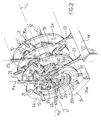
- the rolling mill 1 comprises an outer structure 2 being laid along a rolling axis L and resting on a base B.
- the structure 2 of the rolling mill comprises a plurality of rigidly interconnected members 2a which are parts of respective structures S, joined continuously to one another, of rolling units 5 aligned along the rolling axis L to form the rolling mill 1.
- Each rolling unit 5 includes two members 2a laid side-by-side in the primary structure 2 of the rolling mill, the members 2a forming its outer structure S which accommodates an enclosing roll carrier 10 on its interior consisting, in this example, of a hexagonal frame.
- the carrier 10 is supported slidably along the rolling axis L on a pair of guides 12 disposed within the structure S; it can be locked into an operative position inside the structure S and slid to a non-operative position outside the latter.
- the carriers are packed into the structure 2, being borne on the guides 12 which extend lengthwise of the structure, and means, not shown in the drawings, are provided for the purpose of retaining them in that arrangement.
- rollers 20 Mounted in the carrier 10 are three rolls 20, journalled on respective chocks 21, adapted to be driven rotatively about respective coplanar axes A1, A2 and A3 which lie in a perpendicular plane to the rolling axis L, by means of corresponding extensions 23 to be attached to respective connection shafts 25 of the rolls.
- the rolling unit 5 and the rolling mill 1 include, of course, drive means M for driving the extensions 23.
- the chocks 21, in turn, are mounted on respective swinging arms 30 which are allowed to oscillate about a respective trunnion 31 located on the holder 10.
- Each swinging arm will pivot in a radial plane to the rolling axis L, that is in a perpendicular plane to the rotation axis A1, A2 or A3 of the corresponding roll which contains the rolling axis L.
- each roll in the unit there is also a device 35 for adjusting the position of the roll relative to the rolling axis; such adjustment devices comprise a fixed part 35a rigidly connected to the members 2a, and a moving part 35b which reciprocates along a radial direction to the rolling axis and acts on the roll chocks 21.
- a contrast means 38 effective to hold the rolls in an open position, that is away from the rolling axis, even when they are not acting on a workpiece to be rolled, to counteract the weight of each of them; in this example, this means consists of oil-operated cylinders.
- the roll carrier are staggered along the rolling axis L of the rolling mill such that the sliding directions of the moving portions of the adjustment devices for each roll are, in the instance of a rolling unit having three rolls, rotated 60° from one rolling unit to the next, and in general rotated through an angle of 180°/n, where n is the number of rolls per rolling unit.
- the rolling of rod-shaped or tubular body is carried out on a rolling mill according to the invention, this takes place gradually and accurately on account of at least the three driven rolls being provided for each rolling unit, with the other advantages that characterize rolling mills equipped with three or more driven rolls.
- the rod-shaped or tubular workpiece will be inserted directly or after being fitted over a mandrel, not shown in the drawings, from a feed-in end of the rolling mill and entrained to a feed-out end of the mill by the action of the rolls in the various rolling units.
- the setting of the rolls in each rolling unit can be adjusted to accommodate variations in the shape of their throats, as may result from the periodical re-turning of the rolls.
- the pins on which the arms are hinged will require no positional adjustment on the carrier because it is sufficient that the arm of each roll be rotated to set the roll to a proper distance for repositioning the roll throat relative to the rolling axis.
- the contrast means can be used to advantage for setting the rolls to their desired positions.
- a rolling unit according to the invention can offer a number of advantages.
- the layout of the swinging arms in radial planes to the rolling axis generally prevents the insurgence of roll asymmetries during the releasing and clamping movements from/to a workpiece or as a result of an increased or decreased distance of the roll rotation axis from the rolling axis; also, with the arms arranged as provided by the invention, it becomes possible to increase their radial shack on the pins to facilitate the assembly and disassembly of the swinging arm for the maintenance of the roll carrier.
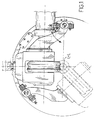
- FIG. 5 a rolling unit is shown which has an outer structure S of the open type, that is one formed of members 2a which are generally C-shaped rather than being annular as in the previously discussed example.
- This embodiment also includes guides 12 along which the roll carrier 10 can be slid between an operative position where it is locked within the structure and a non-operative position for its removal.
- those structural members which, as shown in Figure 5, have the same functions in this modified embodiment as in the previous example, have been denoted by the same numerals.
- the layout of the swinging arms in radial planes to the rolling axis yields the same advantageous results as the previous example.
- the swinging arms could be arranged to oscillate about a respective pin mounted on a carrier extractable from an outer structure, and adjustment devices could be associated with each roll and provided with a moving part active on the arm and a fixed part mounted to the structure, as previously described.
- rolling units may also be used to advantage with rolling mills wherein the rotation axes of the driven or freely rotatable roll pairs are staggered 90° from one unit to the next.
Landscapes
- Engineering & Computer Science (AREA)
- Mechanical Engineering (AREA)
- Metal Rolling (AREA)
- Laminated Bodies (AREA)
- Rigid Pipes And Flexible Pipes (AREA)
- Packaging Of Annular Or Rod-Shaped Articles, Wearing Apparel, Cassettes, Or The Like (AREA)
- Reduction Rolling/Reduction Stand/Operation Of Reduction Machine (AREA)
Applications Claiming Priority (2)
| Application Number | Priority Date | Filing Date | Title |
|---|---|---|---|
| ITMI942661A IT1271808B (it) | 1994-12-28 | 1994-12-28 | Unita' di laminazione per corpi tubolari o astiformi in genere |
| ITMI942661 | 1994-12-28 |
Publications (2)
| Publication Number | Publication Date |
|---|---|
| EP0719600A1 true EP0719600A1 (fr) | 1996-07-03 |
| EP0719600B1 EP0719600B1 (fr) | 1999-10-27 |
Family
ID=11370094
Family Applications (1)
| Application Number | Title | Priority Date | Filing Date |
|---|---|---|---|
| EP95203118A Expired - Lifetime EP0719600B1 (fr) | 1994-12-28 | 1995-11-15 | Une unité de laminage pour laminer des barres ou des corps tubulaires |
Country Status (8)
| Country | Link |
|---|---|
| US (1) | US5765423A (fr) |
| EP (1) | EP0719600B1 (fr) |
| JP (1) | JP3775839B2 (fr) |
| KR (1) | KR960023914A (fr) |
| CN (1) | CN1068803C (fr) |
| AT (1) | ATE185988T1 (fr) |
| DE (1) | DE69513002D1 (fr) |
| IT (1) | IT1271808B (fr) |
Cited By (6)
| Publication number | Priority date | Publication date | Assignee | Title |
|---|---|---|---|---|
| WO1998006515A1 (fr) * | 1996-08-13 | 1998-02-19 | Demag Italimpianti S.P.A. | Laminoir pour calibrer des tubes ou des corps cylindriques en general dans l'industrie siderurgique et metallurgique |
| WO2007014911A1 (fr) * | 2005-07-29 | 2007-02-08 | Danieli & C. Officine Meccaniche S.P.A. | Laminoir muni de cages contenant trois cylindres ajustables |
| WO2007144905A1 (fr) * | 2006-06-12 | 2007-12-21 | Sms Demag Innse S.P.A. | Laminoir à mandrin retenu pour tubes sans soudures |
| WO2010097232A1 (fr) * | 2009-02-26 | 2010-09-02 | Kocks Technik Gmbh & Co.Kg | Cage de laminoir, train de laminoir et utilisation de la cage de laminoir et/ou du train de laminoir pour la réduction de tiges et/ou de tuyaux |
| US8341994B2 (en) | 2008-05-22 | 2013-01-01 | Danieli & C. Officine Meccaniche S.P.A. | Rolling mill stand and related rolling mill for longitudinally rolling rod-shaped bodies |
| IT202000028772A1 (it) * | 2020-11-27 | 2022-05-27 | Danieli Off Mecc | Laminatoio calibratore e/o riduttore per corpi astiformi |
Families Citing this family (17)
| Publication number | Priority date | Publication date | Assignee | Title |
|---|---|---|---|---|
| IT1279085B1 (it) * | 1995-11-29 | 1997-12-04 | Innocenti Eng Spa | Unita' per la laminazione per tubi su mandrino |
| IT1298750B1 (it) * | 1998-03-18 | 2000-02-02 | Demag Italimpianti Spa | Laminatoio a bracci oscillanti,destinato in particolare ma non esclusivamente alla laminazione di tubi senza saldatura |
| CN1270085A (zh) * | 1999-01-15 | 2000-10-18 | 张少渊 | 单(或双)传动输入轴可调式四辊十字轧机 |
| DE19935647C2 (de) * | 1999-07-29 | 2003-10-09 | Kocks Technik | Verfahren zum Walzen von erwärmtem metallischem Gut und Anlage zur Durchführung des Verfahrens |
| RU2345851C2 (ru) * | 2006-03-06 | 2009-02-10 | Открытое акционерное общество "Электростальский завод тяжелого машиностроения" | Рабочая клеть стана продольной прокатки |
| RU2343024C2 (ru) * | 2007-02-01 | 2009-01-10 | Открытое акционерное общество "Электростальский завод тяжелого машиностроения" | Трехвалковая клеть стана продольной прокатки |
| DE102007013902A1 (de) * | 2007-03-20 | 2008-09-25 | Universität Dortmund | Vorrichtung zum Profilbiegen |
| RU2430800C2 (ru) * | 2009-06-15 | 2011-10-10 | Открытое акционерное общество "Электростальский завод тяжелого машиностроения" | Клеть продольной прокатки |
| RU2438807C2 (ru) * | 2009-12-29 | 2012-01-10 | Открытое акционерное общество "Электростальский завод тяжелого машиностроения" | Трехвалковая клеть стана продольной прокатки |
| ES2637412T3 (es) * | 2011-06-22 | 2017-10-13 | Ashley Dean Olsson | Método y dispositivo de conformado de un poste |
| ITMI20111391A1 (it) * | 2011-07-26 | 2013-01-27 | Sms Innse Spa | Cartuccia portarulli per un laminatoio |
| ITMI20130590A1 (it) * | 2013-04-11 | 2014-10-12 | Danieli Off Mecc | Gabbia di laminazione a tre rulli con cambio laterale |
| CN103302101A (zh) * | 2013-07-02 | 2013-09-18 | 中冶赛迪工程技术股份有限公司 | 一种摆臂式轧制机架 |
| CN103599938B (zh) * | 2013-12-03 | 2016-08-17 | 中冶赛迪工程技术股份有限公司 | 四辊连轧管机 |
| CN105728469A (zh) * | 2016-05-10 | 2016-07-06 | 沈阳重机重矿机械设备制造有限公司 | 一种高强度y型轧机机架 |
| CN114130828B (zh) * | 2020-09-03 | 2024-11-12 | 德国考科斯技术有限公司 | 连接系统及其轧辊机架及引导装置 |
| CN116673851A (zh) * | 2023-06-28 | 2023-09-01 | 江西耐乐铜业有限公司 | 一种大口径厚壁管及其热轧冷轧连铸结构 |
Citations (3)
| Publication number | Priority date | Publication date | Assignee | Title |
|---|---|---|---|---|
| FR2398554A1 (fr) * | 1977-07-26 | 1979-02-23 | Ch Polt I | Cage de laminoir |
| EP0264849A2 (fr) * | 1986-10-20 | 1988-04-27 | Sms Schloemann-Siemag Aktiengesellschaft | Laminage de fers marchands à faibles tolérances |
| EP0565772A1 (fr) * | 1992-04-15 | 1993-10-20 | INNSE INNOCENTI ENGINEERING S.p.A. | Cage de laminoir à trois cylindres actionnés et ajustables |
Family Cites Families (2)
| Publication number | Priority date | Publication date | Assignee | Title |
|---|---|---|---|---|
| DE547717C (de) * | 1926-06-04 | 1932-04-01 | E H Gustav Asbeck Dr Ing | Universalwalzwerk |
| IT1264032B (it) * | 1993-04-08 | 1996-09-09 | Filippo Cattaneo | Gabbia di laminazione per laminatoi in generale, a tre o piu' rulli comandati e registrabili |
-
1994
- 1994-12-28 IT ITMI942661A patent/IT1271808B/it active IP Right Grant
-
1995
- 1995-11-15 DE DE69513002T patent/DE69513002D1/de not_active Expired - Lifetime
- 1995-11-15 EP EP95203118A patent/EP0719600B1/fr not_active Expired - Lifetime
- 1995-11-15 AT AT95203118T patent/ATE185988T1/de active
- 1995-11-22 US US08/561,537 patent/US5765423A/en not_active Expired - Lifetime
- 1995-12-26 JP JP33904695A patent/JP3775839B2/ja not_active Expired - Lifetime
- 1995-12-27 CN CN95120118A patent/CN1068803C/zh not_active Expired - Lifetime
- 1995-12-28 KR KR1019950072199A patent/KR960023914A/ko not_active Withdrawn
Patent Citations (4)
| Publication number | Priority date | Publication date | Assignee | Title |
|---|---|---|---|---|
| FR2398554A1 (fr) * | 1977-07-26 | 1979-02-23 | Ch Polt I | Cage de laminoir |
| EP0264849A2 (fr) * | 1986-10-20 | 1988-04-27 | Sms Schloemann-Siemag Aktiengesellschaft | Laminage de fers marchands à faibles tolérances |
| EP0565772A1 (fr) * | 1992-04-15 | 1993-10-20 | INNSE INNOCENTI ENGINEERING S.p.A. | Cage de laminoir à trois cylindres actionnés et ajustables |
| WO1993020960A1 (fr) * | 1992-04-15 | 1993-10-28 | Innse Innocenti Engineering S.P.A. | Montant de cage de laminoir destine a des laminoirs comprenant au moins trois cylindres menes reglables |
Cited By (15)
| Publication number | Priority date | Publication date | Assignee | Title |
|---|---|---|---|---|
| US6116071A (en) * | 1996-08-13 | 2000-09-12 | Demag Italimpianti S.P.A. | Rolling mill for sizing tubes or cylindrical bodies in general in the iron and steel industry |
| WO1998006515A1 (fr) * | 1996-08-13 | 1998-02-19 | Demag Italimpianti S.P.A. | Laminoir pour calibrer des tubes ou des corps cylindriques en general dans l'industrie siderurgique et metallurgique |
| US7849723B2 (en) | 2005-07-29 | 2010-12-14 | Danieli & C. Officine Meccaniche S.P.A. | Rolling mill with stands with three adjustable rolls |
| WO2007014911A1 (fr) * | 2005-07-29 | 2007-02-08 | Danieli & C. Officine Meccaniche S.P.A. | Laminoir muni de cages contenant trois cylindres ajustables |
| RU2396135C2 (ru) * | 2005-07-29 | 2010-08-10 | Даниэли Э К. Оффичине Мекканике С.п.А. | Прокатный стан с клетями и с тремя регулируемыми валками |
| CN102189106B (zh) * | 2005-07-29 | 2012-07-25 | 丹尼利机械设备股份公司 | 具有三个可调辊机架的轧机 |
| WO2007144905A1 (fr) * | 2006-06-12 | 2007-12-21 | Sms Demag Innse S.P.A. | Laminoir à mandrin retenu pour tubes sans soudures |
| EA014479B1 (ru) * | 2006-06-12 | 2010-12-30 | Смс Демаг Иннсе С.П.А. | Прокатный стан с поддерживаемым дорном, предназначенный для бесшовных труб |
| US8341994B2 (en) | 2008-05-22 | 2013-01-01 | Danieli & C. Officine Meccaniche S.P.A. | Rolling mill stand and related rolling mill for longitudinally rolling rod-shaped bodies |
| US8640516B2 (en) | 2008-05-22 | 2014-02-04 | Danieli & C. Officine Meccanicite S.p.A. | Rolling mill stand and related rolling mill for longitudinally rolling rod-shaped bodies |
| US9180502B2 (en) | 2008-05-22 | 2015-11-10 | Danieli & C. Officine Meccaniche S.P.A. | Rolling mill stand and related rolling mill for longitudinally rolling rod-shaped bodies |
| WO2010097232A1 (fr) * | 2009-02-26 | 2010-09-02 | Kocks Technik Gmbh & Co.Kg | Cage de laminoir, train de laminoir et utilisation de la cage de laminoir et/ou du train de laminoir pour la réduction de tiges et/ou de tuyaux |
| IT202000028772A1 (it) * | 2020-11-27 | 2022-05-27 | Danieli Off Mecc | Laminatoio calibratore e/o riduttore per corpi astiformi |
| WO2022112986A1 (fr) * | 2020-11-27 | 2022-06-02 | Danieli & C. Officine Meccaniche S.P.A. | Réducteur et/ou laminoir de calibrage pour corps en forme de tige |
| US12605754B2 (en) | 2020-11-27 | 2026-04-21 | Danieli & C. Officine Meccaniche S.P.A. | Reducer and/or calibrating rolling mill for rod-shaped bodies |
Also Published As
| Publication number | Publication date |
|---|---|
| CN1132671A (zh) | 1996-10-09 |
| US5765423A (en) | 1998-06-16 |
| CN1068803C (zh) | 2001-07-25 |
| JPH08224607A (ja) | 1996-09-03 |
| ITMI942661A1 (it) | 1996-06-28 |
| ITMI942661A0 (it) | 1994-12-28 |
| IT1271808B (it) | 1997-06-09 |
| EP0719600B1 (fr) | 1999-10-27 |
| DE69513002D1 (de) | 1999-12-02 |
| ATE185988T1 (de) | 1999-11-15 |
| KR960023914A (ko) | 1996-07-20 |
| JP3775839B2 (ja) | 2006-05-17 |
Similar Documents
| Publication | Publication Date | Title |
|---|---|---|
| US5765423A (en) | Rolling unit for rolling rod-shaped or tubular bodies | |
| EP0593709B1 (fr) | Montant de cage de laminoir destine a des laminoirs comprenant au moins trois cylindres menes reglables | |
| EP1048371B1 (fr) | Machine à dresser des produits roulés métalliques, comportant des épaulements horizontales ouvrables pour changement rapides des rouleaux | |
| EP0421575B1 (fr) | Guidage adjustable pour éléments rotatifs cylindriques | |
| JP2022502266A (ja) | 弾性的に取り付けられた支持ロールを有している圧延スタンド | |
| US4574606A (en) | Adjusting the rolls in a rolling mill with obliquely oriented, conically contoured rolls | |
| US3543555A (en) | Form changing device for continuous casting | |
| CN110038921B (zh) | 一种焊接钢管定径矫直工艺 | |
| EP0752284B1 (fr) | Cage de laminoir avec module séparable d'ajustement de l'emprise | |
| KR100344378B1 (ko) | 압연기용 조정 가능한 만곡 장치 | |
| US4494394A (en) | Straightening machines and methods | |
| US3347078A (en) | Tube reshaping machine | |
| KR20020064972A (ko) | 연속 주조 주형에서 공동 벽을 가공하기 위한 장치 및 방법 | |
| EP0976468B1 (fr) | Logement pour rouleaux ayant liberté à trois axes | |
| EP0780169B1 (fr) | Block de laminoir compact | |
| US12502700B2 (en) | Rolling mill stand with variable lateral guide device | |
| US4803861A (en) | Guide structure for pierced hollows | |
| US4198841A (en) | Roll mill stand | |
| WO1997003771A1 (fr) | Appareil de formage a rouleaux de guidage pour realiser un tube soude par resistance electrique et appareil a rouleaux a usage double utilisant celui-ci | |
| CN223043311U (zh) | 用于沿轧制轴线轧制金属杆、线或管的支架 | |
| JPH1157813A (ja) | 圧延スタンドの要素及びそれを用いて得られる圧延スタンド | |
| US3459022A (en) | Roller-equipped straightening machine | |
| EP1060802B1 (fr) | Laminoir perceur | |
| JP3297994B2 (ja) | 穿孔圧延機およびキャノン取り換え方法 | |
| SU1731306A1 (ru) | Группа клетей прокатного стана |
Legal Events
| Date | Code | Title | Description |
|---|---|---|---|
| PUAI | Public reference made under article 153(3) epc to a published international application that has entered the european phase |
Free format text: ORIGINAL CODE: 0009012 |
|
| AK | Designated contracting states |
Kind code of ref document: A1 Designated state(s): AT DE ES FR GB IT |
|
| RAP1 | Party data changed (applicant data changed or rights of an application transferred) |
Owner name: INNSE INNOCENTI ENGINEERING SANTEUSTACCHIO S.P.A. |
|
| 17P | Request for examination filed |
Effective date: 19960928 |
|
| 17Q | First examination report despatched |
Effective date: 19980421 |
|
| GRAG | Despatch of communication of intention to grant |
Free format text: ORIGINAL CODE: EPIDOS AGRA |
|
| GRAG | Despatch of communication of intention to grant |
Free format text: ORIGINAL CODE: EPIDOS AGRA |
|
| GRAH | Despatch of communication of intention to grant a patent |
Free format text: ORIGINAL CODE: EPIDOS IGRA |
|
| GRAH | Despatch of communication of intention to grant a patent |
Free format text: ORIGINAL CODE: EPIDOS IGRA |
|
| GRAA | (expected) grant |
Free format text: ORIGINAL CODE: 0009210 |
|
| AK | Designated contracting states |
Kind code of ref document: B1 Designated state(s): AT DE ES FR GB IT |
|
| PG25 | Lapsed in a contracting state [announced via postgrant information from national office to epo] |
Ref country code: ES Free format text: THE PATENT HAS BEEN ANNULLED BY A DECISION OF A NATIONAL AUTHORITY Effective date: 19991027 |
|
| REF | Corresponds to: |
Ref document number: 185988 Country of ref document: AT Date of ref document: 19991115 Kind code of ref document: T |
|
| REF | Corresponds to: |
Ref document number: 69513002 Country of ref document: DE Date of ref document: 19991202 |
|
| PGFP | Annual fee paid to national office [announced via postgrant information from national office to epo] |
Ref country code: AT Payment date: 19991215 Year of fee payment: 5 |
|
| ITF | It: translation for a ep patent filed | ||
| PG25 | Lapsed in a contracting state [announced via postgrant information from national office to epo] |
Ref country code: GB Free format text: LAPSE BECAUSE OF NON-PAYMENT OF DUE FEES Effective date: 20000127 |
|
| PG25 | Lapsed in a contracting state [announced via postgrant information from national office to epo] |
Ref country code: DE Free format text: LAPSE BECAUSE OF FAILURE TO SUBMIT A TRANSLATION OF THE DESCRIPTION OR TO PAY THE FEE WITHIN THE PRESCRIBED TIME-LIMIT Effective date: 20000128 |
|
| ET | Fr: translation filed | ||
| PLBE | No opposition filed within time limit |
Free format text: ORIGINAL CODE: 0009261 |
|
| STAA | Information on the status of an ep patent application or granted ep patent |
Free format text: STATUS: NO OPPOSITION FILED WITHIN TIME LIMIT |
|
| GBPC | Gb: european patent ceased through non-payment of renewal fee |
Effective date: 20000127 |
|
| 26N | No opposition filed | ||
| PG25 | Lapsed in a contracting state [announced via postgrant information from national office to epo] |
Ref country code: AT Free format text: LAPSE BECAUSE OF NON-PAYMENT OF DUE FEES Effective date: 20001115 |
|
| REG | Reference to a national code |
Ref country code: FR Ref legal event code: TP Ref country code: FR Ref legal event code: CD Ref country code: FR Ref legal event code: CA |
|
| REG | Reference to a national code |
Ref country code: FR Ref legal event code: CD Ref country code: FR Ref legal event code: CA |
|
| PGFP | Annual fee paid to national office [announced via postgrant information from national office to epo] |
Ref country code: FR Payment date: 20141201 Year of fee payment: 20 |
|
| PGFP | Annual fee paid to national office [announced via postgrant information from national office to epo] |
Ref country code: IT Payment date: 20141117 Year of fee payment: 20 |