EP0719617A1 - Verfahren und Vorrichtung zum Verschleissausgleich eines Werkstücks Honwerkzeugs auf einer Honmaschine, insbesondere eines nachstellbares Honwerkzeug für Bohrungswänden - Google Patents
Verfahren und Vorrichtung zum Verschleissausgleich eines Werkstücks Honwerkzeugs auf einer Honmaschine, insbesondere eines nachstellbares Honwerkzeug für Bohrungswänden Download PDFInfo
- Publication number
- EP0719617A1 EP0719617A1 EP95402708A EP95402708A EP0719617A1 EP 0719617 A1 EP0719617 A1 EP 0719617A1 EP 95402708 A EP95402708 A EP 95402708A EP 95402708 A EP95402708 A EP 95402708A EP 0719617 A1 EP0719617 A1 EP 0719617A1
- Authority
- EP
- European Patent Office
- Prior art keywords
- lapping
- cycle
- running
- dagger
- value
- Prior art date
- Legal status (The legal status is an assumption and is not a legal conclusion. Google has not performed a legal analysis and makes no representation as to the accuracy of the status listed.)
- Granted
Links
- 238000000034 method Methods 0.000 title claims description 10
- 238000003754 machining Methods 0.000 claims description 12
- 238000006243 chemical reaction Methods 0.000 claims description 2
- 238000006073 displacement reaction Methods 0.000 abstract description 6
- 239000003082 abrasive agent Substances 0.000 description 2
- 230000006870 function Effects 0.000 description 2
- 238000000926 separation method Methods 0.000 description 1
Images

Classifications
-
- B—PERFORMING OPERATIONS; TRANSPORTING
- B24—GRINDING; POLISHING
- B24B—MACHINES, DEVICES, OR PROCESSES FOR GRINDING OR POLISHING; DRESSING OR CONDITIONING OF ABRADING SURFACES; FEEDING OF GRINDING, POLISHING, OR LAPPING AGENTS
- B24B33/00—Honing machines or devices; Accessories therefor
- B24B33/06—Honing machines or devices; Accessories therefor with controlling or gauging equipment
-
- B—PERFORMING OPERATIONS; TRANSPORTING
- B23—MACHINE TOOLS; METAL-WORKING NOT OTHERWISE PROVIDED FOR
- B23Q—DETAILS, COMPONENTS, OR ACCESSORIES FOR MACHINE TOOLS, e.g. ARRANGEMENTS FOR COPYING OR CONTROLLING; MACHINE TOOLS IN GENERAL CHARACTERISED BY THE CONSTRUCTION OF PARTICULAR DETAILS OR COMPONENTS; COMBINATIONS OR ASSOCIATIONS OF METAL-WORKING MACHINES, NOT DIRECTED TO A PARTICULAR RESULT
- B23Q15/00—Automatic control or regulation of feed movement, cutting velocity or position of tool or work
- B23Q15/20—Automatic control or regulation of feed movement, cutting velocity or position of tool or work before or after the tool acts upon the workpiece
- B23Q15/28—Automatic control or regulation of feed movement, cutting velocity or position of tool or work before or after the tool acts upon the workpiece with compensation for tool wear
-
- B—PERFORMING OPERATIONS; TRANSPORTING
- B24—GRINDING; POLISHING
- B24B—MACHINES, DEVICES, OR PROCESSES FOR GRINDING OR POLISHING; DRESSING OR CONDITIONING OF ABRADING SURFACES; FEEDING OF GRINDING, POLISHING, OR LAPPING AGENTS
- B24B33/00—Honing machines or devices; Accessories therefor
- B24B33/08—Honing tools
- B24B33/087—Honing tools provided with measuring equipment
Definitions
- the present invention relates to a method and a device for compensating for wear of a tool for lapping a part on a lapping machine, in particular an expandable lapper for bores.
- Such a device is known, according to which a dagger driven by the piston of a jack secured to the frame of the lapping machine is equipped with cones ensuring the expansion, at each lapping cycle, of abrasive sticks or stones of the lapping rod for the machining of the part.
- the actuator actuating the dagger carrying the expansion cones is controlled so as to always return to the same starting point of the running-in cycle.
- This has the disadvantage that, because at each lapping pass the abrasives wear out, the necessary stroke of the dagger to lead to the machining of bores with the same final diameter will gradually lengthen from cycle to cycle, resulting in thus by a variable cycle time and a variable quality of machining as a function of the stroke of the piston of the expansion cylinder.
- the object of the present invention is to eliminate the above drawback of known devices by proposing a method and a device for compensating for wear of the lapping tool, making it possible to obtain a constant machining cycle throughout the life of the abrasives which is approximately 300 machined parts for a wear of approximately 18 mm to the diameter of the lapping.
- the method of compensating for wear of a lapping tool for a part on a lapping machine, in particular an expandable lapping rod for bores, where the abrasive sticks or lapping stones are subjected at each running-in cycle an expansion by a thrust dagger with expansion cones driven by a piston of the jack is characterized in that it consists in measuring the position value, from an origin of running-in cycle, of the dagger at the end of each cycle of lapping at which the part is fully machined and subtract from the measured value of the dagger position a constant value for deflating the lapping stroke to obtain a new origin for the following lapping cycle.
- the method also consists in determining beforehand the value of the constant deflation stroke of the lap.
- Deflating the lapping is controlled until the calculated new origin of the following lapping cycle is reached.
- the invention also provides a device for compensating for wear of a lapping tool for a part on a lapping machine, in particular an expandable lapping rod for bores, comprising a jack secured to the frame of the lapping machine, a dagger driven by the piston of the jack and equipped with cones ensuring the expansion, at each running-in cycle, of abrasive sticks or stones of the lapping machine for machining the part and which is characterized in that it comprises means for measuring , from a running-in cycle origin, the value of the dagger position at the end of each running-in cycle where the part is fully machined and subtract from the measured value of the dagger position a value of constant deflation stroke of the lapping to obtain a new origin for the following running-in cycle.
- the aforementioned measuring means comprise an element integral with the piston of the aforementioned jack making it possible to identify the position of the dagger and a sensor disposed opposite the identification element so as to to provide a distance value separating the locating element from the sensor proportional to the position of the piston relative to the body of the jack.
- the locating element comprises an inclined part relative to the longitudinal axis of the jack and the sensor is fixed to the body of the jack while also being inclined parallel to the inclined part of the locating element.
- the means making it possible to obtain the new origin of a running-in cycle include a memory means memorizing the value of the abovementioned constant deflation stroke and a calculating means performing, at the end of each running-in cycle, the difference between the value of distance provided by the sensor representing the position of the dagger and the memorized value of constant deflation stroke.
- the aforementioned memory and calculation means are part of an automatic command and control machine for running-in cycles.
- the senor is of the analog type and is connected to the abovementioned calculation means by means of an analog-digital conversion circuit.
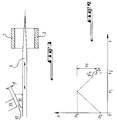
- Figure 1 is a perspective view of an expansion control cylinder and deflating abrasive sticks or stones of an expandable lapping.
- FIG. 2 is a schematic view in longitudinal section of the jack of FIG. 1.
- Figure 3 is a schematic view showing the principle of measuring the displacement of the dagger for expanding the abrasive sticks.
- Figure 4 is a graph showing the position of the dagger as a function of time.
- the reference 1 designates a hydraulic cylinder fixed to the frame of a lapping machine (not shown) and intended during each lapping cycle to control the expansion of the abrasive sticks or stones 2 of an expandable lapping machine for machining bores to a determined final diameter and the retraction or deflation of the abrasive sticks 2 once the machining is finished.
- Such a cylinder 1 is already known per se and only the essential parts thereof will be described below in connection with the invention.
- the jack 1 comprises a piston 3 movable axially in the body 4 of the jack between a high position shown in FIG. 2 and a low position by injecting oil under pressure into an upper annular chamber 5 for the downward movement of the piston 3 and a lower annular chamber 6 for the upward movement of this piston.
- the piston 3 drives in translation a slender piece forming a dagger 7, one end of which comprises cones 8 for expansion or separation, in a radial direction, abrasive sticks 2 by means of a pusher 8a.
- the other end of the dagger 7 is fixed, for example by screwing, to a transverse plate 9 secured to the piston 3.
- the piston 3 comprises, integral with the latter, a locating element 10 projecting outside the cylinder 1 through a window 11 of the body 4 extending parallel to the longitudinal axis of the cylinder 1.
- the locating element 10 comprises a ramp portion 12 inclined with respect to the longitudinal axis of the body 4 of the cylinder and converging towards the upper part of the cylinder in view of FIGS. 1 and 2.
- An analog sensor 13 is fixed to the body 4 of the jack 1 by means of a fixing lug 14 while also being inclined relative to the longitudinal axis of the jack 1 parallel to the part forming a ramp 12 of the locating element 10 and facing this part.
- the device of the invention also comprises an electronic circuit diagrammatically represented at 15 in FIG. 2 comprising a memory in which is stored a constant stroke value called deflation of the lapping, that is to say a constant stroke return value of the dagger 7 after completion of the machining operation of a bore to the desired final diameter.
- deflation is accompanied by a radial approximation of the abrasive sticks 2 towards the longitudinal axis of the dagger 7.
- the electronic circuit 15 is connected to the analog sensor 13 and may include a converter which converts the measured analog values of distance d between the sensor 13 and the locating element 10 into digital form.
- the electronic circuit 15 is also suitable for calculating, at the end of each running-in cycle where the machining operation of the bore to the desired final diameter is carried out, the difference between the position value relative to the body 4 of the cylinder 1 of the dagger 7 and the value of the constant deflation stroke of the lapping so as to obtain a new origin of the following running-in cycle as will become clear from the description which follows.
- the electronic circuit 15 is part of the automaton (not shown) controlling and controlling the running-in cycles of the bores.
- the analog-digital converter is associated with the analog sensor 13, the latter can be easily connected to input cards of conventional automata.
- the automaton controls the displacement of the piston 3 from its upper original position or starting point of the first running-in cycle, which is accompanied by a concomitant displacement in translation of the dagger 7 relative to the body 4 of the jack.
- the displacement of the dagger 7 produces an expansion of the abrasive sticks 2 by pushing them radially out of the axis of the dagger 7 as symbolized by the double arrow in FIG. 2 until the abrasive sticks 2 have machined the bore corresponding to a diameter or theoretical dimension desired corresponding to the end of the running-in cycle.
- the displacement of the dagger 7 at the end of this running-in cycle is determined by measuring the distance d between the sensor 13 and the inclined part 12 of the locating element 10 shown in dotted lines in FIG.
- FIG. 4 shows the expansion stroke of the dagger 7 of duration t 1 from the starting position P 0 of the dagger 7 to its position P 1 at the end of the machining cycle of the corresponding bore.
- the circuit 15 makes the difference between the corresponding value measured d by the analog sensor 13 and the memorized value of the constant deflation stroke of the lap to calculate a new origin or new starting point for the following running-in cycle.
- the automatic device then controls deflation of the lapping, that is to say the return of the dagger 7 until reaching the new calculated starting point of the following running-in cycle.
- FIG. 4 shows the new calculated starting point P'o of the dagger 7 for a new following running-in cycle, the distance u between Po 'and Po being representative of the wear of the abrasive sticks of the lapping, Vc symbolizing the constant value of deflation occurring between instants t 1 and t 2 .
- the process of compensating for the abrasive wear of a lapping tool according to the invention therefore makes it possible to effectively eliminate the drawback of the known prior methods according to which the dagger carrying the expansion cones always returned to the same starting point. , which gradually lengthened, during the running-in cycles, the stroke necessary for the dagger to machine the bores to the same final theoretical diameter.
Landscapes
- Engineering & Computer Science (AREA)
- Mechanical Engineering (AREA)
- Finish Polishing, Edge Sharpening, And Grinding By Specific Grinding Devices (AREA)
- Constituent Portions Of Griding Lathes, Driving, Sensing And Control (AREA)
- Grinding Of Cylindrical And Plane Surfaces (AREA)
Applications Claiming Priority (2)
| Application Number | Priority Date | Filing Date | Title |
|---|---|---|---|
| FR9415719 | 1994-12-27 | ||
| FR9415719A FR2728493A1 (fr) | 1994-12-27 | 1994-12-27 | Procede et dispositif de rattrapage d'usure d'un outil de rodage d'une piece sur une machine de rodage, notamment d'un rodoir expansible pour alesages |
Publications (2)
| Publication Number | Publication Date |
|---|---|
| EP0719617A1 true EP0719617A1 (de) | 1996-07-03 |
| EP0719617B1 EP0719617B1 (de) | 2000-01-12 |
Family
ID=9470291
Family Applications (1)
| Application Number | Title | Priority Date | Filing Date |
|---|---|---|---|
| EP19950402708 Expired - Lifetime EP0719617B1 (de) | 1994-12-27 | 1995-11-30 | Verfahren und Vorrichtung zum Verschleissausgleich eines Werkstücks Honwerkzeugs auf einer Honmaschine, insbesondere eines nachstellbares Honwerkzeug für Bohrungswänden |
Country Status (4)
| Country | Link |
|---|---|
| EP (1) | EP0719617B1 (de) |
| DE (1) | DE69514493T2 (de) |
| ES (1) | ES2143025T3 (de) |
| FR (1) | FR2728493A1 (de) |
Families Citing this family (2)
| Publication number | Priority date | Publication date | Assignee | Title |
|---|---|---|---|---|
| WO2009109064A1 (en) * | 2008-03-05 | 2009-09-11 | Abb Technology Ab | A method for compensation tool wear and a machine tool for performing the method |
| CN114953053B (zh) * | 2022-06-27 | 2023-06-09 | 东莞市翔泉家具有限公司 | 一种多功能办公桌加工用桌面切割装置 |
Citations (4)
| Publication number | Priority date | Publication date | Assignee | Title |
|---|---|---|---|---|
| DE2442243A1 (de) * | 1973-09-04 | 1975-03-20 | Toyo Kogyo Co | Honstein-ausschiebevorrichtung |
| EP0063983A1 (de) * | 1981-04-16 | 1982-11-03 | Automobiles Citroen | Honmaschine |
| GB2115324A (en) * | 1982-02-24 | 1983-09-07 | Ex Cell O Corp | Single pass sizing tool and machine including wear compensation means |
| EP0430817A1 (de) * | 1989-11-30 | 1991-06-05 | Societe Procedes Machines Speciales S.P.M.S. | Expansions-Läppvorrichtung für Bohrungen |
-
1994
- 1994-12-27 FR FR9415719A patent/FR2728493A1/fr active Granted
-
1995
- 1995-11-30 DE DE1995614493 patent/DE69514493T2/de not_active Expired - Fee Related
- 1995-11-30 ES ES95402708T patent/ES2143025T3/es not_active Expired - Lifetime
- 1995-11-30 EP EP19950402708 patent/EP0719617B1/de not_active Expired - Lifetime
Patent Citations (4)
| Publication number | Priority date | Publication date | Assignee | Title |
|---|---|---|---|---|
| DE2442243A1 (de) * | 1973-09-04 | 1975-03-20 | Toyo Kogyo Co | Honstein-ausschiebevorrichtung |
| EP0063983A1 (de) * | 1981-04-16 | 1982-11-03 | Automobiles Citroen | Honmaschine |
| GB2115324A (en) * | 1982-02-24 | 1983-09-07 | Ex Cell O Corp | Single pass sizing tool and machine including wear compensation means |
| EP0430817A1 (de) * | 1989-11-30 | 1991-06-05 | Societe Procedes Machines Speciales S.P.M.S. | Expansions-Läppvorrichtung für Bohrungen |
Also Published As
| Publication number | Publication date |
|---|---|
| EP0719617B1 (de) | 2000-01-12 |
| FR2728493B1 (de) | 1997-02-14 |
| FR2728493A1 (fr) | 1996-06-28 |
| DE69514493D1 (de) | 2000-02-17 |
| ES2143025T3 (es) | 2000-05-01 |
| DE69514493T2 (de) | 2000-07-27 |
Similar Documents
| Publication | Publication Date | Title |
|---|---|---|
| EP0262039A1 (de) | Lünette für Schleifmaschine mit Lade- und Entladeautomat für Walzwerkwalzen | |
| EP1751513B1 (de) | Verfahren zur kontrolle der zugspannung eines bolzenschaftes wie etwa einer schraube oder eines spannstiftes sowie verfahren zur durchführung dieses verfahrens | |
| FR2627119A1 (fr) | Procedes de detection d'usinabilite et de coupe | |
| WO1997013614A1 (fr) | Dispositif de mesure ou de controle de l'usinage d'une piece cylindrique a mouvement orbital | |
| FR2641211A1 (fr) | Machine a cintrer et procede de cintrage de pieces en forme de feuilles | |
| CA2326648C (fr) | Procede pour mesurer par ultrasons la tension residuelle d'une barre de precontrainte | |
| EP0715932B1 (de) | Verfahren und Vorrichtung zum Einstellen des Schlaghubes einer, von einem inkompressiblen Fluid angetriebenen, Schlagvorrichtung | |
| FR2565638A1 (fr) | Verin pneumatique comportant un mecanisme de deceleration | |
| FR2559822A1 (fr) | Outil hydraulique pour la mise sous tension de cables, tiges et organes similaires dans des structures en beton | |
| FR2637831A1 (fr) | Machine et outil pour le traitement de pieces a usiner par pierrage | |
| CA3037781A1 (fr) | Procede d'engagement de deux elements engrenage et dispositif d'entrainement mettant en oeuvre un tel procede | |
| EP0719617B1 (de) | Verfahren und Vorrichtung zum Verschleissausgleich eines Werkstücks Honwerkzeugs auf einer Honmaschine, insbesondere eines nachstellbares Honwerkzeug für Bohrungswänden | |
| EP3546792B1 (de) | Verfahren zum eingriff zweier zahnräder und antriebsvorrichtung zur durchführung eines derartigen verfahrens | |
| FR2513163A1 (fr) | Dispositif d'abrasion de disques de frein d'automobiles | |
| EP0091010A1 (de) | Kraftmessvorrichtung | |
| WO1981002543A1 (fr) | Mecanisme de presse hydraulique | |
| US3992914A (en) | Rolling operations | |
| FR2509850A1 (fr) | Jauge de controle du jeu entre les cames d'un arbre a cames et les soupapes correspondantes | |
| EP0327774B1 (de) | Abflussvorrichtung zur Leerung eines Membranspeichers | |
| FR2600919A1 (fr) | Procede et dispositif pour la retouche due a l'usure des cylindres d'un laminoir, sur la ligne de laminage | |
| EP2218827A1 (de) | Vorrichtung zur Druckbeaufschlagung einer Schachteinfassung | |
| EP1186568B1 (de) | Hubarbeitsbühne und Verfahren zum Steuern einer sich darauf befindenden Last | |
| KR0153566B1 (ko) | 호닝가공방법 및 호닝가공장치 | |
| FR2699609A1 (fr) | Procédé et dispositif pour la mise en mouvement ou l'arrêt d'un moteur hydraulique entraînant un ensemble présentant une grande inertie. | |
| EP1462214A1 (de) | Verfahren und Vorrichtung zur Lageerfassung eines mechanischen Teils in einer Aufnahme |
Legal Events
| Date | Code | Title | Description |
|---|---|---|---|
| PUAI | Public reference made under article 153(3) epc to a published international application that has entered the european phase |
Free format text: ORIGINAL CODE: 0009012 |
|
| AK | Designated contracting states |
Kind code of ref document: A1 Designated state(s): DE ES GB IT |
|
| 17P | Request for examination filed |
Effective date: 19961104 |
|
| GRAG | Despatch of communication of intention to grant |
Free format text: ORIGINAL CODE: EPIDOS AGRA |
|
| 17Q | First examination report despatched |
Effective date: 19990325 |
|
| GRAG | Despatch of communication of intention to grant |
Free format text: ORIGINAL CODE: EPIDOS AGRA |
|
| GRAG | Despatch of communication of intention to grant |
Free format text: ORIGINAL CODE: EPIDOS AGRA |
|
| GRAH | Despatch of communication of intention to grant a patent |
Free format text: ORIGINAL CODE: EPIDOS IGRA |
|
| GRAH | Despatch of communication of intention to grant a patent |
Free format text: ORIGINAL CODE: EPIDOS IGRA |
|
| GRAA | (expected) grant |
Free format text: ORIGINAL CODE: 0009210 |
|
| AK | Designated contracting states |
Kind code of ref document: B1 Designated state(s): DE ES GB IT |
|
| REF | Corresponds to: |
Ref document number: 69514493 Country of ref document: DE Date of ref document: 20000217 |
|
| ITF | It: translation for a ep patent filed | ||
| GBT | Gb: translation of ep patent filed (gb section 77(6)(a)/1977) |
Effective date: 20000322 |
|
| REG | Reference to a national code |
Ref country code: ES Ref legal event code: FG2A Ref document number: 2143025 Country of ref document: ES Kind code of ref document: T3 |
|
| PLBE | No opposition filed within time limit |
Free format text: ORIGINAL CODE: 0009261 |
|
| STAA | Information on the status of an ep patent application or granted ep patent |
Free format text: STATUS: NO OPPOSITION FILED WITHIN TIME LIMIT |
|
| 26N | No opposition filed | ||
| PGFP | Annual fee paid to national office [announced via postgrant information from national office to epo] |
Ref country code: GB Payment date: 20011128 Year of fee payment: 7 |
|
| PGFP | Annual fee paid to national office [announced via postgrant information from national office to epo] |
Ref country code: DE Payment date: 20011217 Year of fee payment: 7 |
|
| PGFP | Annual fee paid to national office [announced via postgrant information from national office to epo] |
Ref country code: ES Payment date: 20011228 Year of fee payment: 7 |
|
| REG | Reference to a national code |
Ref country code: GB Ref legal event code: IF02 |
|
| PG25 | Lapsed in a contracting state [announced via postgrant information from national office to epo] |
Ref country code: GB Free format text: LAPSE BECAUSE OF NON-PAYMENT OF DUE FEES Effective date: 20021130 |
|
| PG25 | Lapsed in a contracting state [announced via postgrant information from national office to epo] |
Ref country code: ES Free format text: LAPSE BECAUSE OF NON-PAYMENT OF DUE FEES Effective date: 20021201 |
|
| PG25 | Lapsed in a contracting state [announced via postgrant information from national office to epo] |
Ref country code: DE Free format text: LAPSE BECAUSE OF NON-PAYMENT OF DUE FEES Effective date: 20030603 |
|
| GBPC | Gb: european patent ceased through non-payment of renewal fee | ||
| REG | Reference to a national code |
Ref country code: ES Ref legal event code: FD2A Effective date: 20031213 |
|
| PG25 | Lapsed in a contracting state [announced via postgrant information from national office to epo] |
Ref country code: IT Free format text: LAPSE BECAUSE OF NON-PAYMENT OF DUE FEES;WARNING: LAPSES OF ITALIAN PATENTS WITH EFFECTIVE DATE BEFORE 2007 MAY HAVE OCCURRED AT ANY TIME BEFORE 2007. THE CORRECT EFFECTIVE DATE MAY BE DIFFERENT FROM THE ONE RECORDED. Effective date: 20051130 |