EP0719687A2 - Connecteur de test pour dispositif de test automatique - Google Patents
Connecteur de test pour dispositif de test automatique Download PDFInfo
- Publication number
- EP0719687A2 EP0719687A2 EP95105262A EP95105262A EP0719687A2 EP 0719687 A2 EP0719687 A2 EP 0719687A2 EP 95105262 A EP95105262 A EP 95105262A EP 95105262 A EP95105262 A EP 95105262A EP 0719687 A2 EP0719687 A2 EP 0719687A2
- Authority
- EP
- European Patent Office
- Prior art keywords
- test connector
- stem
- test
- recited
- openings
- Prior art date
- Legal status (The legal status is an assumption and is not a legal conclusion. Google has not performed a legal analysis and makes no representation as to the accuracy of the status listed.)
- Granted
Links
Images



Classifications
-
- B—PERFORMING OPERATIONS; TRANSPORTING
- B60—VEHICLES IN GENERAL
- B60T—VEHICLE BRAKE CONTROL SYSTEMS OR PARTS THEREOF; BRAKE CONTROL SYSTEMS OR PARTS THEREOF, IN GENERAL; ARRANGEMENT OF BRAKING ELEMENTS ON VEHICLES IN GENERAL; PORTABLE DEVICES FOR PREVENTING UNWANTED MOVEMENT OF VEHICLES; VEHICLE MODIFICATIONS TO FACILITATE COOLING OF BRAKES
- B60T17/00—Component parts, details, or accessories of power brake systems not covered by groups B60T8/00, B60T13/00 or B60T15/00, or presenting other characteristic features
- B60T17/18—Safety devices; Monitoring
- B60T17/22—Devices for monitoring or checking brake systems; Signal devices
- B60T17/228—Devices for monitoring or checking brake systems; Signal devices for railway vehicles
-
- B—PERFORMING OPERATIONS; TRANSPORTING
- B60—VEHICLES IN GENERAL
- B60T—VEHICLE BRAKE CONTROL SYSTEMS OR PARTS THEREOF; BRAKE CONTROL SYSTEMS OR PARTS THEREOF, IN GENERAL; ARRANGEMENT OF BRAKING ELEMENTS ON VEHICLES IN GENERAL; PORTABLE DEVICES FOR PREVENTING UNWANTED MOVEMENT OF VEHICLES; VEHICLE MODIFICATIONS TO FACILITATE COOLING OF BRAKES
- B60T17/00—Component parts, details, or accessories of power brake systems not covered by groups B60T8/00, B60T13/00 or B60T15/00, or presenting other characteristic features
- B60T17/04—Arrangements of piping, valves in the piping, e.g. cut-off valves, couplings or air hoses
- B60T17/043—Brake line couplings, air hoses and stopcocks
Definitions
- This invention relates to the automatic testing of railroad car brake equipment and particularly to means for directly accessing specific fluid pressure channels of brake control valve devices for use in conducting automatic testing of the car air brakes.
- test ports are provided on this single valve mounting face generally intermediate the respective valve portions.
- An access housing having access ports communicated with the test ports facilities access to the test ports.
- the object of the present invention is to provide a multi-probe test connector for establishing fluid pressure communication between the pipe bracket test ports of a control valve device and an automatic tester for conducting the single car test.
- a more specific object of the invention is to provide a multi-probe test connector having self-aligning probes, each adapted to assure engagement of a respective one of the pipe bracket test ports without requiring such close manufacturing tolerances as to be cost prohibitive.
- a still further object of the invention is to provide a test connector having an open and a closed position to permit installation of the test connector without concurrently opening the check valves incorporated in the access ports, thereby preventing any inadvertent escape of pressurized air during such installation.
- a test connector in which a plurality of actuator stems are mounted on an eccentric shaft that can be rotated by a handle between open and closed positions. In the closed handle position, the actuator stems are retracted, so that when installing the test connector in position, the check valves remain closed to prevent any escape of compressed air from the access ports. Movement of the handle to open position when it is desired to initiate the automatic test extends the actuator stems to engage and unseat the access port check valves so that air can flow therefrom to the test device.
- a plurality of test probes are pivotally mounted in the test connector body in axially fixed relationship with the access port check valves, so that in the course of installing the test connector, the test probes engage and unseat the access port check valves. In this manner, air is automatically accessed for conducting the automatic test.
- the actuator stems/test probes are self-aligning with the access ports to facilitate installation of the test connector.
- the preferred, single-faced pipe bracket portion 12 includes a front side 14 and a back side 16, the front side 14 having mounted thereto an emergency portion 18 and service portion 20.
- Both the emergency and service portions, 18, 20, as shown, are mounted by any suitable means such as by using threaded bolts or studs.
- the emergency portion 18 and service portion 20 are mounted upon opposite ends of front face 14.
- the emergency portion 18 and service portion 20 are spaced apart a selected amount such that an area or space is provided between the emergency portion 18 and the service portion 20 on the front face 14 of pipe bracket portion 12.
- a brake pipe connection (not shown) connects a brake pipe to the pipe bracket portion 12 and is provided at the back side 16 of the pipe bracket portion 12.
- a brake cylinder, a brake cylinder retaining valve, an emergency reservoir and an auxiliary reservoir(each not shown) are also connected to the back side 16 of the pipe bracket portion 12, by any suitable means, such as by pipes and flanged fittings.
- a retainer 52 and a dirt collector 50 are also connected to the pipe bracket portion back side 16.
- the preferred pipe bracket portion 12 is shown having the emergency portion 18 and the service portion 20 detached therefrom.
- the emergency portion 18 is mountable to a mounting surface 24 on the pipe bracket portion front side 14 and the service portion 20 is also mountable to a mounting surface 26 on the pipe bracket portion front side 14.
- Between the mounting surface 24 and the mounting surface 26 lies an area on pipe bracket portion front side 14 in which are located four test ports 28, 30, 32, 34.
- Test port 28 connects to the brake cylinder passageway, test port 30 to the brake pipe passageway, test port 32 to the auxiliary reservoir passageway and test port 34 to the emergency reservoir passageway (the passageways are not shown in Fig. 2).
- the test ports 28, 30, 32, 34 are located upon a mounting surface or boss 54 of the pipe bracket portion 12.
- the boss 54 is preferably integral with the pipe bracket portion 12 and its surface is preferably planar. Threaded screw holes 36 are also preferably provided on boss 54. Fluid pressure in each air line may be monitored by accessing the air through the test ports 28, 30, 32, 34.
- an access housing 56 is shown attached to the pipe bracket portion 12. As can be seen, the access housing 56 is mounted upon the pipe bracket portion front side 14 at boss 54. The access housing 56 may be affixed to the pipe bracket portion front side 14 by any convenient means such as by housing screws 61. Preferably, the access housing 56 has a planar surface which mates with the planar surface of boss 54. It is further preferred that a gasket be provided between the access housing 56 and the pipe bracket portion first side 14.
- access housing 56 has channels 62, 64, 66, 68 for communicating with the respective test ports 28, 30, 32, 34.
- the housing channels 62, 64, 66, 68 have opposed ends, with one end of each channel 62, 64, 66, 68 being sized and configured to connect to and sealably engage with the respective test ports 28, 30, 32, 34.
- the housing channels 62, 64, 66, 68 are positioned in the access housing 56 such that when the access housing 56 is placed in contact with boss 54, the housing channels 62, 64, 66, 68 are aligned with the respective test ports, 28, 30, 32, 34 of the pipe bracket portion front side 14.
- Access housing 56 has check valves provided therein.
- a number of check valves are provided within the access housing 56, such that a respective check valve is provided within each of the housing channels 62, 64, 66, 68.
- Each such check valve is preferably comprised of a spring 70 seated within the housing channel, and a valve element 72 engageable with the spring 70, which together operate in connection with the valve seat 74.
- the valve elements 72 of these check valves are each movable within their respective housing channels 62, 64, 66, 68 and are normally biased by the springs 70 into contact with the valve seats 74. With check valve elements 72 in biased contact with the respective valve seats 74, the check valves are said to be in a closed position, in which fluid at the test ports 28, 30, 32, 34 is prevented from escaping through the access housing 56.
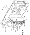
- test connector 58 is attached to access housing 56 when it is desired to access the fluid pressures of the various test ports 28, 30, 32, 34.
- the preferred test connector 58 and the access housing 56 may be connected by any convenient means such as by screws 94 that pass through holes 95 in test connector 58 and engage threaded holes 96 in access housing 56.
- Test connector 58 has through channels 78, 80, 82, 84 that are aligned with the respective access housing channels 62, 64, 66, 68 when the test connector is bolted in place on access housing 56.
- Seal rings 98 surround the test connector through channels at the interface between the test connector and access housing to provide a fluid pressure seal thereat.
- the through channels have hose fittings 100 threaded thereto, such fittings having a barbed end to which a hose (not shown) may be connected from a test device (not shown).
- a rotary actuator 102 is disposed in a bore 104 that is transverse to through channels 78, 80, 82, 84.
- Seal rings 106 are provided on the periphery of rotary actuator 102 at each side of the through channels 78, 80, 82, 84 to seal bore 104 against fluid pressure leakage.
- Actuator 102 is formed with an annular recess 101 intermediate seal rings 106 via which fluid pressure effective in the respective through channels 78, 80, 82, 84 is able to flow past actuator 102.
- Each recess is such that an eccentric 108 is formed on actuator 102 at the intersection of each through channel 78, 80, 82, 84 with bore 104.
- An actuator stem 110 formed preferably of plastic is attached at one end on each eccentric 108 so as to have limited axial movement thereon. This limited axial movement is defined by axially spaced stop shoulders 112 formed at each recess 101, for a purpose hereinafter explained.
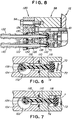
- the attached end of the stems 110 are generally U-shaped so as to fit over eccentric 108 with sufficient clearance as to permit relative rotation therebetween. As shown in Figs. 6 and 7, this U-shaped end of stem 110 is non-continuous, in that the end is open, such opening being slightly smaller than eccentric 108 to allow the end to be snap-fit over the eccentric by reason of the elastic nature of plastic.
- Stems 110 are disposed in through channels 78, 80, 82, 84 and in corresponding housing channels 62, 64, 66, 68 such that each end of stem 110 opposite the connected end is located adjacent a respective check valve element 72.
- a handle 112 operates in a slot 114 in the test connector body and is assembled onto one end of actuator 102 in any suitable manner to effect rotation of the actuator in response to handle movement between open and closed positions. Movement of handle 112 is limited to approximately 90° rotation by engagement with the ends of slot 114 to define such open and closed positions of the handle.
- this opposite end of actuator stem 110 is generally bulbous-shaped, having a plurality of tapered flutes 116. The tapered flutes 116 facilitate entry of the respective actuator stems into access housing channels 62, 64, 66, 68, as the test connector 58 is assembled in position.
- access housing channels 62, 64, 66, 68 at the interface with the corresponding test connector channels are chamfered to cooperate with the tapered flutes 116 in order to provide for self-alignment of the actuator stems without requiring close manufacturing tolerances between the access housing and test connector parts.
- handle 112 is shifted from its normal closed position at one end of slot 114 to its open position at the other extreme end of slot 114.
- actuator 102 is rotated approximately 90°, whereby the actuator eccentric 108 is repositioned such as to extend actuator stem 110 sufficiently to engage and unseat check valve element 72 against the force of spring 70 at each of the respective access channels 62, 64, 66, 68.
- pressurized air is free to flow from the respective access channels to the automated tester via valve seat 74, flutes 116 of actuator stem 110, and the test connector through channels, without any escape of air either during the assembly of the test connector onto the access housing or thereafter.
- the axis of bore 104 is offset from the centerline of the respective through channels 78, 80, 82, 84 and aligned access channels 62, 64, 66, 68 in order to minimize the amount of lateral displacement or throw of eccentric 108 between the open and closed positions of handle 112 and thereby limit the amount of rocking motion of actuator stem 110.
- the existing rocking motion at the opposite or bulbous-shaped end of actuator stem 110 is accommodated by the spherical shape of the bulbous end thereof. This, in turn, allows the size of the bulbous end of actuator stem 110 to be substantially the same as the diameter of the respective access channel in order to assure equal distribution of the lifting force on the access channel check valves.
- a preferably circular locator vane 118 is formed coaxially on actuator stem 110 intermediate its ends. In the closed handle position, and prior to assembly of test connector 58 onto access housing 56, this locator vane engages the respective through channel 78, 80, 82, 84 such as to support actuator stem 110 nearly perpendicular to the test connector mounting face and thereby provide for pre-alignment of the bulbous end of the actuator stem 110.
- the connected end of a respective actuator stem 110 is free to shift axially on its eccentric 108 within the limits set by shoulders 112. This accommodates alignment of the actuator stem in an axial direction, as required by the guided, self-aligning action of the bulbous end of actuator stem 110 during assembly of the test connector 58 onto access housing 56.
- handle 112 is shifted to its closed position in which actuator 102 is rotated approximately 90° in the opposite direction. Accordingly, eccentric 108 is rotated to its normal position, as shown in Fig. 6, to retract actuator stems 110 and thereby allow closure of the respective check valves. In this manner, no escape of pressurized air occurs during such removal of the test connector 58 from access housing 56.
- test connector 120 An alternate embodiment of a test connector 120 is shown in Fig. 8.
- several test probes 122 are mounted on a probe plate 124 that is adapted to be bolted to access housing 56 in a manner similar to that of the preferred embodiment.
- Probe plate 124 is formed with a series of through openings 126 (only two being shown) that correspond in number and are aligned generally with through channels 62, 64, 66, 68 in access housing 56. Openings 126 are formed with a shoulder 128 on which a resilient member, such as an O-ring 130, rests.
- Test probes 122 include at one end a barbed hose fitting 132 to which a test hose of an automatic tester, for example, is connected.
- the opposite end 133 of test probes 122 are adapted to project into the respective access housing channel 62, 64, 66, 68 for engagement with check valve element 72.
- annular swivel flange 134 having a spherically-shaped surface that is received in through opening 126 with a relatively snug fit.
- a snap ring 136 bears against one side of swivel flange 134, while the other side bears against O-ring 130.
- O-ring 130 acts in the manner of a centering spring to maintain test probes 122 generally perpendicular to the mounting face of probe plate 124.
- Another O-ring 138 is carried on the periphery of test probe 122 between its opposite end 133 and swivel flange 134. This O-ring 134 is adapted to engage and provide a pressure seal with access channel 68, as will hereinafter be explained.
- a central passage 140 that extends through test probes 122 and radial passages 142 communicates with central passage 140 at a location between O-ring 138 and opposite end 133 of test probes 122.
- test connector 120 When it is desired to conduct an automatic test, the test connector 120 is assembled onto access housing 56 and bolted in place, as by bolts 94. During such assembly, the projecting opposite end 133 of test probes 122 enter the respective access housing channels 62, 64, 66, 68, such access channels being preferably chamfered at the opening thereof to gather the test probes. In the event misalignment exists between any of the test probes and their respective access channels, the opposite end 133 of a misaligned test probe will engage the access channel chamfer, causing the test probe to rotate about its swivel flange 134 to a slightly cocked position.
- O-ring 130 allows for such cocking of test probe 122 by becoming compressed between shoulder 128 and swivel flange 134.
- test connector 120 When test connector 120 is mounted in place on access housing 56, the other end of test probes 120 will engage and unseat the respective access channel check valves against springs 70. In this manner, the pressurized air effective in the access housing channels is conducted to the automatic tester (not shown) via valve seat 74, radial passages 142 and central passage 140 of test probe 122. In order to accommodate such cocking of any one of the test probes 120 without binding, the periphery of each test probe on both sides of O-ring 138 is arcuatly-shaped.
- test probes 122 Upon disassembly of test connector 120 from access housing 56, test probes 122 are withdrawn and the access channel check valves are seated by springs 70 to prevent escape of pressurized air from the access housing channels.
Landscapes
- Engineering & Computer Science (AREA)
- Transportation (AREA)
- Mechanical Engineering (AREA)
- Valves And Accessory Devices For Braking Systems (AREA)
Applications Claiming Priority (2)
| Application Number | Priority Date | Filing Date | Title |
|---|---|---|---|
| US33616094A | 1994-12-29 | 1994-12-29 | |
| US336160 | 1994-12-29 |
Publications (3)
| Publication Number | Publication Date |
|---|---|
| EP0719687A2 true EP0719687A2 (fr) | 1996-07-03 |
| EP0719687A3 EP0719687A3 (fr) | 1996-12-27 |
| EP0719687B1 EP0719687B1 (fr) | 2000-03-15 |
Family
ID=23314844
Family Applications (1)
| Application Number | Title | Priority Date | Filing Date |
|---|---|---|---|
| EP19950105262 Expired - Lifetime EP0719687B1 (fr) | 1994-12-29 | 1995-04-07 | Connecteur de test pour dispositif de test automatique |
Country Status (2)
| Country | Link |
|---|---|
| EP (1) | EP0719687B1 (fr) |
| DE (1) | DE69515623T2 (fr) |
Cited By (1)
| Publication number | Priority date | Publication date | Assignee | Title |
|---|---|---|---|---|
| CN112526407A (zh) * | 2020-11-24 | 2021-03-19 | 国网新疆电力有限公司信息通信公司 | 电力数字配线架2m端口连接装置及端口测试方法 |
Family Cites Families (4)
| Publication number | Priority date | Publication date | Assignee | Title |
|---|---|---|---|---|
| US1997749A (en) * | 1933-06-05 | 1935-04-16 | New York Air Brake Co | Clamping device for air brake test racks |
| DE1228437B (de) * | 1963-02-18 | 1966-11-10 | Karlheinz Klein | Pruefgeraet fuer Druckluftbremseinrichtungen von Motorlastwagen und/oder Lastwagenanhaengern |
| US3727453A (en) * | 1969-05-05 | 1973-04-17 | Chicago Pneumatic Tool Co | Apparatus for testing air brake control valves |
| DE3001679C2 (de) * | 1980-01-18 | 1984-07-19 | Wabco Westinghouse Fahrzeugbremsen GmbH, 3000 Hannover | Lastabhäniger Bremskraftregler |
-
1995
- 1995-04-07 EP EP19950105262 patent/EP0719687B1/fr not_active Expired - Lifetime
- 1995-04-07 DE DE1995615623 patent/DE69515623T2/de not_active Expired - Fee Related
Cited By (2)
| Publication number | Priority date | Publication date | Assignee | Title |
|---|---|---|---|---|
| CN112526407A (zh) * | 2020-11-24 | 2021-03-19 | 国网新疆电力有限公司信息通信公司 | 电力数字配线架2m端口连接装置及端口测试方法 |
| CN112526407B (zh) * | 2020-11-24 | 2024-03-19 | 国网新疆电力有限公司信息通信公司 | 电力数字配线架2m端口连接装置及端口测试方法 |
Also Published As
| Publication number | Publication date |
|---|---|
| EP0719687A3 (fr) | 1996-12-27 |
| DE69515623D1 (de) | 2000-04-20 |
| DE69515623T2 (de) | 2000-11-02 |
| EP0719687B1 (fr) | 2000-03-15 |
Similar Documents
| Publication | Publication Date | Title |
|---|---|---|
| USRE34781E (en) | Coupling adapter | |
| US5503011A (en) | Test connector for automatic test device | |
| US5183078A (en) | Combination shut-off and test-injection valve | |
| CA2153854C (fr) | Connecteur pour dispositif d'essai automatique | |
| US7028986B2 (en) | Valve actuator apparatus | |
| US3308850A (en) | Cable actuated multi-fitting gas valves | |
| US4930748A (en) | Shutoff and regulating valve | |
| US5451099A (en) | Railway brake pipe bracket access plate | |
| US4231387A (en) | Backflow preventing valve | |
| US4598734A (en) | Alarm check valve | |
| CN113266683A (zh) | 具有不受阻挡的流动路径且具有增大的流量系数的阀 | |
| JPH0612306B2 (ja) | 計測装置を有する流体系統 | |
| EP0719687B1 (fr) | Connecteur de test pour dispositif de test automatique | |
| US4794937A (en) | Plug coupling | |
| CN113266682A (zh) | 具有不受阻挡的流动路径且具有增大的流量系数的阀 | |
| US5801298A (en) | In-line valve seat leak flow testing apparatus | |
| US5714684A (en) | Test plat adapter for manual single car tester | |
| CN221569577U (zh) | 一种双阀塞电动调节阀 | |
| US4565211A (en) | Hydraulic manifold with automatic flow control | |
| EP0156554B1 (fr) | Accouplement de rupture | |
| AU6806298A (en) | Dual seal coupling apparatus for enabling quick measurement of brake cylinder pressure | |
| US5952566A (en) | Dual valve apparatus for enabling quick measurement of pressure | |
| US4497467A (en) | Plug valve with hydraulically actuated seals | |
| US5901984A (en) | Coupling mechanism for connecting a fluid line to a mass flow controller or other device | |
| US5293777A (en) | Hinged assembly for air brake valve test fixture |
Legal Events
| Date | Code | Title | Description |
|---|---|---|---|
| PUAI | Public reference made under article 153(3) epc to a published international application that has entered the european phase |
Free format text: ORIGINAL CODE: 0009012 |
|
| AK | Designated contracting states |
Kind code of ref document: A2 Designated state(s): DE GB |
|
| PUAL | Search report despatched |
Free format text: ORIGINAL CODE: 0009013 |
|
| RHK1 | Main classification (correction) |
Ipc: B60T 17/22 |
|
| AK | Designated contracting states |
Kind code of ref document: A3 Designated state(s): DE GB |
|
| 17P | Request for examination filed |
Effective date: 19970210 |
|
| 17Q | First examination report despatched |
Effective date: 19980722 |
|
| GRAG | Despatch of communication of intention to grant |
Free format text: ORIGINAL CODE: EPIDOS AGRA |
|
| GRAG | Despatch of communication of intention to grant |
Free format text: ORIGINAL CODE: EPIDOS AGRA |
|
| GRAH | Despatch of communication of intention to grant a patent |
Free format text: ORIGINAL CODE: EPIDOS IGRA |
|
| GRAH | Despatch of communication of intention to grant a patent |
Free format text: ORIGINAL CODE: EPIDOS IGRA |
|
| GRAA | (expected) grant |
Free format text: ORIGINAL CODE: 0009210 |
|
| AK | Designated contracting states |
Kind code of ref document: B1 Designated state(s): DE GB |
|
| REF | Corresponds to: |
Ref document number: 69515623 Country of ref document: DE Date of ref document: 20000420 |
|
| EN | Fr: translation not filed | ||
| PLBE | No opposition filed within time limit |
Free format text: ORIGINAL CODE: 0009261 |
|
| STAA | Information on the status of an ep patent application or granted ep patent |
Free format text: STATUS: NO OPPOSITION FILED WITHIN TIME LIMIT |
|
| 26N | No opposition filed | ||
| REG | Reference to a national code |
Ref country code: GB Ref legal event code: IF02 |
|
| PGFP | Annual fee paid to national office [announced via postgrant information from national office to epo] |
Ref country code: GB Payment date: 20020403 Year of fee payment: 8 |
|
| PGFP | Annual fee paid to national office [announced via postgrant information from national office to epo] |
Ref country code: DE Payment date: 20020418 Year of fee payment: 8 |
|
| PG25 | Lapsed in a contracting state [announced via postgrant information from national office to epo] |
Ref country code: GB Free format text: LAPSE BECAUSE OF NON-PAYMENT OF DUE FEES Effective date: 20030407 |
|
| PG25 | Lapsed in a contracting state [announced via postgrant information from national office to epo] |
Ref country code: DE Free format text: LAPSE BECAUSE OF NON-PAYMENT OF DUE FEES Effective date: 20031101 |
|
| GBPC | Gb: european patent ceased through non-payment of renewal fee |
Effective date: 20030407 |