EP0719952B1 - Befestigungselement aus zwei gleitenden Elementen - Google Patents
Befestigungselement aus zwei gleitenden Elementen Download PDFInfo
- Publication number
- EP0719952B1 EP0719952B1 EP95308473A EP95308473A EP0719952B1 EP 0719952 B1 EP0719952 B1 EP 0719952B1 EP 95308473 A EP95308473 A EP 95308473A EP 95308473 A EP95308473 A EP 95308473A EP 0719952 B1 EP0719952 B1 EP 0719952B1
- Authority
- EP
- European Patent Office
- Prior art keywords
- nut
- insert
- substrate
- fastening assembly
- panel
- Prior art date
- Legal status (The legal status is an assumption and is not a legal conclusion. Google has not performed a legal analysis and makes no representation as to the accuracy of the status listed.)
- Expired - Lifetime
Links
- 239000000758 substrate Substances 0.000 claims description 17
- 239000004033 plastic Substances 0.000 claims description 13
- 229920003023 plastic Polymers 0.000 claims description 13
- 230000014759 maintenance of location Effects 0.000 claims description 3
- 239000000463 material Substances 0.000 claims 1
- 239000002184 metal Substances 0.000 claims 1
- 230000000712 assembly Effects 0.000 description 2
- 238000000429 assembly Methods 0.000 description 2
- 238000006073 displacement reaction Methods 0.000 description 1
- 239000000446 fuel Substances 0.000 description 1
- 230000007246 mechanism Effects 0.000 description 1
- 230000002093 peripheral effect Effects 0.000 description 1
Images
Classifications
-
- F—MECHANICAL ENGINEERING; LIGHTING; HEATING; WEAPONS; BLASTING
- F16—ENGINEERING ELEMENTS AND UNITS; GENERAL MEASURES FOR PRODUCING AND MAINTAINING EFFECTIVE FUNCTIONING OF MACHINES OR INSTALLATIONS; THERMAL INSULATION IN GENERAL
- F16B—DEVICES FOR FASTENING OR SECURING CONSTRUCTIONAL ELEMENTS OR MACHINE PARTS TOGETHER, e.g. NAILS, BOLTS, CIRCLIPS, CLAMPS, CLIPS OR WEDGES; JOINTS OR JOINTING
- F16B5/00—Joining sheets or plates, e.g. panels, to one another or to strips or bars parallel to them
- F16B5/02—Joining sheets or plates, e.g. panels, to one another or to strips or bars parallel to them by means of fastening members using screw-thread
- F16B5/0241—Joining sheets or plates, e.g. panels, to one another or to strips or bars parallel to them by means of fastening members using screw-thread with the possibility for the connection to absorb deformation, e.g. thermal or vibrational
-
- F—MECHANICAL ENGINEERING; LIGHTING; HEATING; WEAPONS; BLASTING
- F16—ENGINEERING ELEMENTS AND UNITS; GENERAL MEASURES FOR PRODUCING AND MAINTAINING EFFECTIVE FUNCTIONING OF MACHINES OR INSTALLATIONS; THERMAL INSULATION IN GENERAL
- F16B—DEVICES FOR FASTENING OR SECURING CONSTRUCTIONAL ELEMENTS OR MACHINE PARTS TOGETHER, e.g. NAILS, BOLTS, CIRCLIPS, CLAMPS, CLIPS OR WEDGES; JOINTS OR JOINTING
- F16B37/00—Nuts or like thread-engaging members
- F16B37/04—Devices for fastening nuts to surfaces, e.g. sheets, plates
- F16B37/041—Releasable devices
- F16B37/043—Releasable devices with snap action
-
- F—MECHANICAL ENGINEERING; LIGHTING; HEATING; WEAPONS; BLASTING
- F16—ENGINEERING ELEMENTS AND UNITS; GENERAL MEASURES FOR PRODUCING AND MAINTAINING EFFECTIVE FUNCTIONING OF MACHINES OR INSTALLATIONS; THERMAL INSULATION IN GENERAL
- F16B—DEVICES FOR FASTENING OR SECURING CONSTRUCTIONAL ELEMENTS OR MACHINE PARTS TOGETHER, e.g. NAILS, BOLTS, CIRCLIPS, CLAMPS, CLIPS OR WEDGES; JOINTS OR JOINTING
- F16B2200/00—Constructional details of connections not covered for in other groups of this subclass
- F16B2200/97—Constructional details of connections not covered for in other groups of this subclass having differing thermal expansion coefficients
-
- Y—GENERAL TAGGING OF NEW TECHNOLOGICAL DEVELOPMENTS; GENERAL TAGGING OF CROSS-SECTIONAL TECHNOLOGIES SPANNING OVER SEVERAL SECTIONS OF THE IPC; TECHNICAL SUBJECTS COVERED BY FORMER USPC CROSS-REFERENCE ART COLLECTIONS [XRACs] AND DIGESTS
- Y10—TECHNICAL SUBJECTS COVERED BY FORMER USPC
- Y10S—TECHNICAL SUBJECTS COVERED BY FORMER USPC CROSS-REFERENCE ART COLLECTIONS [XRACs] AND DIGESTS
- Y10S411/00—Expanded, threaded, driven, headed, tool-deformed, or locked-threaded fastener
- Y10S411/904—Fastener or fastener element composed of nonmetallic material
- Y10S411/908—Resinous material
Definitions
- the present invention relates generally to automotive fastener assemblies, and more specifically to fastener assemblies for securing plastics finish panels to metallic substrates, according to the preamble of claim 1.
- plastics finish panels have come into widespread use and even broader use is planned for the future.
- Most of the uses of plastics finish panels in the automotive vehicle arts require that a plastics sheet or panel be secured to an underlying metallic substrate through suitable fasteners.
- one of the primary fastening systems of choice is the use of a threaded fastener spanning the two components to be secured together and exerting a clamping load between them.
- the mounting of a plastics body panel on a metallic substrate such as a frame or underbody, certain impediments to the presentation of a finish panel of good quality and appearance have been experienced.
- the significant difference in coefficient of thermal expansion between the plastics panel and the metallic substrate tends to result in displacement between these two components, and when a fastener is arranged to hold the panel fast with respect to the substrate, distortion can result.
- French Patent 2554522 A describes an adjustable assembly fixing for joining on support to a panel-shaped component consisting of a box-shaped element which fits into a rectangular aperture in the panel and contains a wedging element for a screw.
- the box-shaped element has ribs and flexible shoulders so it can grip the edges of the rectangular aperture and grooves along its sides which enable the wedging element to slide in it.
- the wedging element has a threaded hole for the screw and an expanding base to anchor it to the box-shaped element.
- the teaching of French Patent 2554522 is acknowledged in the preamble of claim 1.
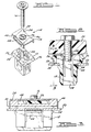
- a fastener assembly 10 is illustrated as generally including an insert member 12, a nut member 14, and an externally threaded fastener such as a screw 16.
- the insert member 12 is a plastics moulded part of generally T-shaped cross-section. It includes a lower plug portion 18 of generally box-like configuration and an upper nut mounting portion 20, likewise of generally box-like configuration, of larger cross-section than the plug portion 18.
- An annular face 22 is formed on the underside of the nut mounting portion 20 and a plurality (four shown) of barbs 24 are formed integrally with plug portion 18 on its outer peripheral surfaces in spaced relationship with respect to the annular face 22 measured along the longitudinal extent of the plug portion 18.
- the plug portion 18 is referred to as defining a longitudinal axis notwithstanding its box-like rectangular configuration, its downwardly extending axis of symmetry being inferred.
- the nut mounting portion 22 also has a plurality (two shown) of generally triangular projections or barbs 26 projecting from two slide surfaces 28, 30 formed on the longer sides of the nut mounting portion 20, as viewed in Figure 1.
- Centring tabs indicated generally at 30, 32 in Figure 1 project perpendicularly from the ends of the slide surfaces 28, 30 to assist in locating the nut 16 with respect to the insert 12.
- the nut 14 is preferably formed as a generally C-shaped member having a base portion 34 having a dished, internally threaded aperture 36 formed through it and terminating at laterally spaced, downwardly projecting slide arms 38, 40.
- the nut 14 is fabricated as a metallic member and includes longitudinally extending slots 46, 48 formed through the slide arms 38, 40, respectively.
- FIG 2 the fixed securement of a plastics finish panel 50 to a metallic substrate 52 through the agency of the fastening assembly 10 is illustrated.
- the insert member 12 is inserted through an aperture 54 formed in the metallic substrate 52 and the barbs 24 slide through the aperture 54 and snap back to retain the insert 12 in snap-fit retention with respect to the metallic substrate 52.
- the nut 14 is likewise presented to the nut mounting portion 20 of the insert 12, and by the agency of the projections 26 co-operating with the guide slots 46, 48, snap-fit retention in the axial direction of the nut 14 with respect to the insert 12 is effected.
- the screw 16 may then be introduced through a clearance hole 56 provided in the finish panel 50 to engage the threaded aperture 36 in the nut 14 and clampingly secure the finish panel 50 with respect to the metallic substrate 52.
- the screw 16 can be carried along with the deflecting panel 50 and can be permitted to move the nut 14 a limited amount in the direction of the slots 46, 48 until the projection 26 contacts either end of the slots 46, 48.
- a hollow cavity 58 is formed in the insert 12 for receiving a portion of the nut 16 being sized to permit the certain movement described.
Landscapes
- Engineering & Computer Science (AREA)
- General Engineering & Computer Science (AREA)
- Mechanical Engineering (AREA)
- Connection Of Plates (AREA)
Claims (4)
- Eine Haltevorrichtung zur Befestigung eines mit Kunststoff beschichteten Paneels (50) auf einer Unterlage aus Metall (52), wobei die Unterlage eine Montageöffnung (54) hat, die sich senkrecht von einer äusseren Fläche der Unterlage erstreckt, wobei die Haltevorrichtung (10) enthält:dadurch gekennzeichnet dass die besagte Mutter (14) einen langen Führungsschlitz (46, 48) enthält, der durch jeden der besagten Seitenabschnitte (38, 40) gebildet ist und dass eine Vorrichtung (26) auf der besagten Vorrichtung gebildet ist, die die Gleitflächen auf dem besagten Mutter-Montageabschnitt (28) bildet und die im Betrieb in den besagten Schlitz (46, 48) der Mutter eingreift und ein Schnapp-Einpasseingreifen zwischen der besagten Mutter und dem besagten Einsatz ausführt, um eine verhältnismässige Bewegung in zwei entegengesetzte Richtungen zwischen der besagten Mutter (14) und dem besagten Einsatz (12) zu begrenzen.eine Mutter (14), die im allgemeinen C-förmig ist, und die einen Grundlagenabschnitt (34) mit Gewinden (36) enthält, die durch ihn gebildet sind und zwei seitlich auseinanderliegende Seitenabschnitte (38, 40), die senkrecht aus dem besagten Grundlagenabschnitt (34) hervorragen und sich längs aus dem Grundlagenabschnitt (34) erstrecken;ein Einsatzglied (12) mit einem im allgemeinen schachtelähnlichen Stopfenabschnitt (18), der im Schnapp-Einpassverhältnis in der besagten Montageöffnung (54) der Unterlage aufgenommen werden kann, einen vergrösserten Mutter-Montageabschnitt (28), der aus einem im allgemeinen rechteckigen Querschnitt an einem Ende des besagten Stopfenabschnitts (18) gebildet ist und als ein Teil mit ihm geformt ist, wobei der Mutter-Montageabschnitt einen grösseren Querschnitt als der besagte Stopfenabschnitt (18) hat, um eine im allgemeinen T-förmige, abgestufte Auslegung des besagten Einsatzaglieds (12) zu bilden, wobei Vorrichtungen sich längs erstreckende Gleitflächen auf dem besagten Mutter-Montageabschnitt (28) bilden, der die besagte Mutter zum gleitenden Eingreifen zwischen ihnen aufnimmt und einen Halter (16) mit Gewinde, der in der besagten Mutter (14) aufgenommen wird und im Betrieb in das besagte Paneel (50) eingreifen kann, um das besagte Paneel (50) auf der besagten Unterlage (52) zu befestigen;
- Eine Haltevorrichtung nach Anspruch 1, in der der besagte Einsatz-Stopfenabschnitt (18) eine Vielzahl von Barten (24) enthält, die sich nach aussen vom Rand erstrecken, um die besagte Schnapp-Einpass-Zurückhaltung in der besagten Öffnung (54) der Unterlage auszuführen.
- Eine Haltevorrichtung nach Anspruch 1 oder 2, in der das besagte Mittel zur Begrenzung und Ausführung des Eingreifens mindestens eine Öse (26) enthält, die mit dem besagten Einsatzglied-Mutter-Montageabschnitt (28) gebildet ist und die durch den besagten Mutterführungsschlitz (46, 48) hervorragt.
- Eine Haltevorrichtung nach irgendeinem der vorhergehenden Ansprüche, in der das besagte Einsatzglied (12) aus einem Kunststoff hergestellt ist und das besagte Mutterglied (14) aus Metall gefertigt ist.
Applications Claiming Priority (2)
| Application Number | Priority Date | Filing Date | Title |
|---|---|---|---|
| US08/364,335 US5536125A (en) | 1994-12-27 | 1994-12-27 | Sliding two-piece fastener |
| US364335 | 1994-12-27 |
Publications (2)
| Publication Number | Publication Date |
|---|---|
| EP0719952A1 EP0719952A1 (de) | 1996-07-03 |
| EP0719952B1 true EP0719952B1 (de) | 2000-01-26 |
Family
ID=23434040
Family Applications (1)
| Application Number | Title | Priority Date | Filing Date |
|---|---|---|---|
| EP95308473A Expired - Lifetime EP0719952B1 (de) | 1994-12-27 | 1995-11-27 | Befestigungselement aus zwei gleitenden Elementen |
Country Status (4)
| Country | Link |
|---|---|
| US (1) | US5536125A (de) |
| EP (1) | EP0719952B1 (de) |
| BR (1) | BR9505890A (de) |
| DE (1) | DE69514769T2 (de) |
Families Citing this family (42)
| Publication number | Priority date | Publication date | Assignee | Title |
|---|---|---|---|---|
| US5692953A (en) * | 1995-06-09 | 1997-12-02 | Ford Global Technologies, Inc. | Automotive cowl screen assembly |
| US6183180B1 (en) * | 1996-01-19 | 2001-02-06 | Fatigue Technology, Inc. | Wall nut and bolt assemblies |
| FR2745343B1 (fr) * | 1996-02-26 | 1998-05-15 | Itw De France | Ecrou de pre-assemblage en matiere plastique |
| US5855461A (en) * | 1997-07-23 | 1999-01-05 | Tripi; Timothy | Anchor for a threaded fastener |
| FR2768196B1 (fr) * | 1997-09-05 | 1999-10-29 | Renault | Fixation auto-liberante au serrage, notamment pour une aile plastique d'un vehicule automobile |
| US6553615B1 (en) | 2000-09-21 | 2003-04-29 | Illinois Tool Works Inc. | Two-piece sliding grommet |
| DE10142528B8 (de) * | 2001-08-30 | 2009-12-03 | A. Raymond Et Cie | Befestigungsklammer zur Verankerung eines Bauteils in einem Loch einer Trägerplatte |
| US6726418B2 (en) | 2001-09-19 | 2004-04-27 | Eustathios Vassiliou Revocable Trust | Spring fastener for connecting automotive components and other articles |
| US20040081534A1 (en) * | 2002-08-06 | 2004-04-29 | Dickinson Daniel James | Fastener for connecting automotive components and other articles |
| JP3961406B2 (ja) * | 2002-11-19 | 2007-08-22 | ポップリベット・ファスナー株式会社 | カーテンエアバッグの固着具 |
| US7118138B1 (en) | 2003-09-19 | 2006-10-10 | Mercury Plastics, Inc. | Quick connect fastener and connection |
| DE10359110B4 (de) * | 2003-12-17 | 2006-07-20 | A. Raymond & Cie | Vorrichtung zum Verbinden eines Trägerteiles mit einem Anbauteil |
| FR2881802B1 (fr) * | 2005-02-07 | 2007-04-27 | Itw Fastex France Soc Par Acti | Cage pour dispositif de fixation et dispositif comportant une telle cage |
| FR2889156B1 (fr) * | 2005-07-29 | 2007-10-26 | Faurecia Interieur Ind Snc | Element de garnissage destine a etre monte sur une piece d'equipement de vehicule automobile, piece et procede de montage associes |
| DE102005060137B4 (de) * | 2005-12-16 | 2008-09-11 | A. Raymond Et Cie | Blechmutter |
| US8172635B2 (en) * | 2006-01-12 | 2012-05-08 | Taiwan Semiconductor Manufacturing Co., Ltd. | Alignment device and method for aligning apertures in different plates |
| US7698787B2 (en) * | 2006-01-18 | 2010-04-20 | Illinois Tool Works Inc. | Fastener |
| US7438350B1 (en) | 2007-06-26 | 2008-10-21 | Honda Motor Company, Ltd. | Vehicles having fastener extending into apertures of respective body panels and methods |
| US7537271B2 (en) * | 2007-06-26 | 2009-05-26 | Honda Motor Company, Ltd. | All terrain vehicles having swivel clip and methods |
| US7527323B2 (en) * | 2006-07-27 | 2009-05-05 | Honda Motor Company, Ltd. | All terrain vehicles having midpoint fastener and methods |
| US7530629B2 (en) * | 2007-06-26 | 2009-05-12 | Honda Motor Company, Ltd. | Panel assemblies, vehicles, and methods of manufacturing |
| US7597387B2 (en) * | 2006-07-27 | 2009-10-06 | Honda Motor Company, Ltd. | All terrain vehicles and fender assemblies therefor |
| US7523981B2 (en) * | 2007-06-26 | 2009-04-28 | Honda Motor Company, Ltd. | All terrain vehicles having seat with compression surface |
| US7591503B2 (en) * | 2006-07-27 | 2009-09-22 | Honda Motor Company, Ltd. | All terrain vehicle having layered body panel configuration |
| US7510236B2 (en) * | 2006-07-27 | 2009-03-31 | Honda Motor Company, Ltd. | All terrain vehicles having fender assembly |
| US7527322B2 (en) * | 2007-06-26 | 2009-05-05 | Honda Motor Company, Ltd. | All terrain vehicles having stay assembly |
| US7736082B1 (en) | 2006-09-21 | 2010-06-15 | Mattheis Harley H | Fastening system for assembling plastic units and rib clip therefor |
| US20100007156A1 (en) * | 2008-01-28 | 2010-01-14 | Pokowski Aaron D | Glove box striker with box clip attachment feature |
| CA2773314C (en) * | 2009-09-09 | 2017-11-21 | The Monadnock Company | Panel fastener, panel assembly and methods of assembly and installation |
| FR2957643B1 (fr) * | 2010-03-17 | 2012-06-15 | Clusienne Clufix | Dispositif de retenue |
| US8807895B2 (en) * | 2011-07-13 | 2014-08-19 | Toyota Motor Engineering & Manufacturing North America, Inc. | Fastener housing for securing a bumper fascia to a fender panel of an automotive vehicle |
| US9297408B2 (en) * | 2014-01-30 | 2016-03-29 | GM Global Technology Operations LLC | Coupling spacer, assembly, and method |
| DE102015012869A1 (de) * | 2015-10-05 | 2017-04-06 | Man Truck & Bus Ag | Verfahren und Vorrichtung zur Befestigung eines Kunststoffbauteils an einem tragenden Bauteil |
| US9520658B1 (en) * | 2016-01-28 | 2016-12-13 | Deere & Company | Fastener assembly |
| US11692570B2 (en) | 2016-11-04 | 2023-07-04 | Newfrey Llc | Pin and grommet fastener accommodating two directional offset and related methods |
| US10288098B2 (en) | 2016-11-04 | 2019-05-14 | Newfrey Llc | Pin and grommet fastener accommodating two directional offset and related methods |
| US10344792B2 (en) * | 2017-01-20 | 2019-07-09 | Ford Global Technologies, Llc | Receiver assembly |
| US10900514B2 (en) * | 2017-11-07 | 2021-01-26 | Hellermanntyton Corporation | Wire-tray-assembly with stud-mount inserts |
| US10408248B1 (en) | 2018-09-05 | 2019-09-10 | Newfrey Llc | Sealing pin and grommet fastener accommodating two directional offset |
| US11451025B2 (en) | 2020-12-22 | 2022-09-20 | Hellermann Tyton Corporation | Wire tray and mounting insert assemblies |
| JP2023140378A (ja) * | 2022-03-23 | 2023-10-05 | 富士フイルムビジネスイノベーション株式会社 | ネジ締結構造およびそれを備えた装置 |
| US20250172164A1 (en) * | 2023-11-29 | 2025-05-29 | GM Global Technology Operations LLC | Compression limiter with retention capabilities |
Family Cites Families (18)
| Publication number | Priority date | Publication date | Assignee | Title |
|---|---|---|---|---|
| USRE17870E (en) * | 1925-07-22 | 1930-11-18 | Tkneb cobeobation | |
| US3217772A (en) * | 1964-04-17 | 1965-11-16 | Bishop & Babcock Corp | Front end mounting cage nut fastener |
| US3400743A (en) * | 1965-05-18 | 1968-09-10 | Tinnerman Products Inc | Sheet metal fastener with resilient arms |
| US3646982A (en) * | 1969-09-12 | 1972-03-07 | Rex Chainbelt Inc | Encapsulated floating and nonfloating fasteners |
| US3678798A (en) * | 1969-12-29 | 1972-07-25 | Eaton Corp | Fastening device |
| US3875661A (en) * | 1973-09-10 | 1975-04-08 | Gen Motors Corp | Flexible panel subassembly for a vehicle |
| US5046904A (en) * | 1990-08-13 | 1991-09-10 | General Motors Corporation | Nut for mounting trim to a motor vehicle |
| US4529244A (en) * | 1982-11-19 | 1985-07-16 | General Motors Corporation | Plastic vehicle body panel mounting structure |
| US4573733A (en) * | 1982-11-19 | 1986-03-04 | General Motors Corporation | Apparatus for mounting plastic body panel |
| JPS59171714A (ja) * | 1983-03-04 | 1984-09-28 | Honda Motor Co Ltd | 自動車用ドア |
| FR2554522B1 (fr) * | 1983-11-08 | 1986-04-18 | Renault | Dispositif d'assemblage |
| US4707020A (en) * | 1985-07-16 | 1987-11-17 | Honda Giken Kogyo Kabushiki Kaisha | Body structure of a motor vehicle having exterior panels made of synthetic resins |
| FR2621361B1 (fr) * | 1987-10-05 | 1990-01-12 | Materiel Equip Tech Cie | Perfectionnements aux systemes de fixation comportant des ecrous emprisonnes dans des cages |
| GB2223554B (en) * | 1988-08-26 | 1992-07-22 | Titus Tool Co Ltd | Adjustable fixing device |
| US4973102A (en) * | 1989-11-16 | 1990-11-27 | Chrysler Corporation | Fastening arrangement for plastic to metal parts |
| US5098765A (en) * | 1989-12-22 | 1992-03-24 | Chrysler Corportion | Fastening arrangement for plastic vehicle panel |
| US5129768A (en) * | 1992-01-08 | 1992-07-14 | Illinois Tool Works Inc. | Sliding grommet |
| US5228742A (en) * | 1992-09-28 | 1993-07-20 | General Motors Corporation | Apparatus for connecting composite vehicle body panels to composite vehicle underbodies |
-
1994
- 1994-12-27 US US08/364,335 patent/US5536125A/en not_active Expired - Fee Related
-
1995
- 1995-11-27 DE DE69514769T patent/DE69514769T2/de not_active Expired - Fee Related
- 1995-11-27 EP EP95308473A patent/EP0719952B1/de not_active Expired - Lifetime
- 1995-12-14 BR BR9505890A patent/BR9505890A/pt not_active Application Discontinuation
Also Published As
| Publication number | Publication date |
|---|---|
| US5536125A (en) | 1996-07-16 |
| DE69514769D1 (de) | 2000-03-02 |
| EP0719952A1 (de) | 1996-07-03 |
| BR9505890A (pt) | 1998-01-06 |
| DE69514769T2 (de) | 2000-09-28 |
Similar Documents
| Publication | Publication Date | Title |
|---|---|---|
| EP0719952B1 (de) | Befestigungselement aus zwei gleitenden Elementen | |
| CA2316609C (en) | Pushnut | |
| US5205692A (en) | Three-axes variability compensating fastener | |
| US4875816A (en) | Caged fastener | |
| US5667271A (en) | Snap-in attachment clip for plastic panel | |
| US7226260B2 (en) | Sheet metal fastening clip | |
| EP0892892B1 (de) | Blindschnappbefestigungselement | |
| US5347690A (en) | Fastener apparatus for an automotive body panel component | |
| US20050236861A1 (en) | Multiple stage assembly assist fastener | |
| US20050052056A1 (en) | Apparatus and method for attaching undercover onto underside of car floor panel | |
| CA2298950A1 (en) | Caged nut assembly | |
| US5249900A (en) | Threaded fastener for mounting within an opening in a panel | |
| JPS641344B2 (de) | ||
| US6257794B1 (en) | Sliding mount for securing a plastics motor vehicle body part piece on a support | |
| US5951223A (en) | Self-retaining snap-in clip | |
| CA2057134A1 (en) | Three axis variability compensating fastener | |
| JPH08240207A (ja) | 部品の仮止め用クリップ及び該クリップを用いた部品の仮止め構造 | |
| EP3502490B1 (de) | Systeme zur linearen verriegelung | |
| US5753859A (en) | Fitting structure for electrical connection box | |
| US20040012218A1 (en) | Clip for attaching a corner cladding to a vehicle | |
| JP3004874B2 (ja) | ナットとナット保持部材 | |
| JPH051686Y2 (de) | ||
| JPH0529168Y2 (de) | ||
| JP3448656B2 (ja) | 配線・配管材用受具の連結構造及び連結具 | |
| US12313110B2 (en) | Fastener |
Legal Events
| Date | Code | Title | Description |
|---|---|---|---|
| PUAI | Public reference made under article 153(3) epc to a published international application that has entered the european phase |
Free format text: ORIGINAL CODE: 0009012 |
|
| AK | Designated contracting states |
Kind code of ref document: A1 Designated state(s): DE FR GB |
|
| 17P | Request for examination filed |
Effective date: 19961111 |
|
| 17Q | First examination report despatched |
Effective date: 19980729 |
|
| GRAG | Despatch of communication of intention to grant |
Free format text: ORIGINAL CODE: EPIDOS AGRA |
|
| GRAG | Despatch of communication of intention to grant |
Free format text: ORIGINAL CODE: EPIDOS AGRA |
|
| GRAH | Despatch of communication of intention to grant a patent |
Free format text: ORIGINAL CODE: EPIDOS IGRA |
|
| GRAH | Despatch of communication of intention to grant a patent |
Free format text: ORIGINAL CODE: EPIDOS IGRA |
|
| GRAA | (expected) grant |
Free format text: ORIGINAL CODE: 0009210 |
|
| AK | Designated contracting states |
Kind code of ref document: B1 Designated state(s): DE FR GB |
|
| PG25 | Lapsed in a contracting state [announced via postgrant information from national office to epo] |
Ref country code: FR Free format text: LAPSE BECAUSE OF FAILURE TO SUBMIT A TRANSLATION OF THE DESCRIPTION OR TO PAY THE FEE WITHIN THE PRESCRIBED TIME-LIMIT Effective date: 20000126 |
|
| REF | Corresponds to: |
Ref document number: 69514769 Country of ref document: DE Date of ref document: 20000302 |
|
| EN | Fr: translation not filed | ||
| PGFP | Annual fee paid to national office [announced via postgrant information from national office to epo] |
Ref country code: DE Payment date: 20001102 Year of fee payment: 6 |
|
| PGFP | Annual fee paid to national office [announced via postgrant information from national office to epo] |
Ref country code: GB Payment date: 20001110 Year of fee payment: 6 |
|
| PLBE | No opposition filed within time limit |
Free format text: ORIGINAL CODE: 0009261 |
|
| STAA | Information on the status of an ep patent application or granted ep patent |
Free format text: STATUS: NO OPPOSITION FILED WITHIN TIME LIMIT |
|
| 26N | No opposition filed | ||
| PG25 | Lapsed in a contracting state [announced via postgrant information from national office to epo] |
Ref country code: GB Free format text: LAPSE BECAUSE OF NON-PAYMENT OF DUE FEES Effective date: 20011127 |
|
| REG | Reference to a national code |
Ref country code: GB Ref legal event code: IF02 |
|
| PG25 | Lapsed in a contracting state [announced via postgrant information from national office to epo] |
Ref country code: DE Free format text: LAPSE BECAUSE OF NON-PAYMENT OF DUE FEES Effective date: 20020702 |
|
| GBPC | Gb: european patent ceased through non-payment of renewal fee |
Effective date: 20011127 |