EP0719962A2 - Tendeur de courroie crantée - Google Patents
Tendeur de courroie crantée Download PDFInfo
- Publication number
- EP0719962A2 EP0719962A2 EP95120222A EP95120222A EP0719962A2 EP 0719962 A2 EP0719962 A2 EP 0719962A2 EP 95120222 A EP95120222 A EP 95120222A EP 95120222 A EP95120222 A EP 95120222A EP 0719962 A2 EP0719962 A2 EP 0719962A2
- Authority
- EP
- European Patent Office
- Prior art keywords
- lever
- toothed
- toothed belt
- drive
- shaft
- Prior art date
- Legal status (The legal status is an assumption and is not a legal conclusion. Google has not performed a legal analysis and makes no representation as to the accuracy of the status listed.)
- Granted
Links
Images

Classifications
-
- F—MECHANICAL ENGINEERING; LIGHTING; HEATING; WEAPONS; BLASTING
- F16—ENGINEERING ELEMENTS AND UNITS; GENERAL MEASURES FOR PRODUCING AND MAINTAINING EFFECTIVE FUNCTIONING OF MACHINES OR INSTALLATIONS; THERMAL INSULATION IN GENERAL
- F16H—GEARING
- F16H7/00—Gearings for conveying rotary motion by endless flexible members
- F16H7/08—Means for varying tension of belts, ropes or chains
- F16H7/10—Means for varying tension of belts, ropes or chains by adjusting the axis of a pulley
- F16H7/12—Means for varying tension of belts, ropes or chains by adjusting the axis of a pulley of an idle pulley
- F16H7/1254—Means for varying tension of belts, ropes or chains by adjusting the axis of a pulley of an idle pulley without vibration damping means
-
- F—MECHANICAL ENGINEERING; LIGHTING; HEATING; WEAPONS; BLASTING
- F16—ENGINEERING ELEMENTS AND UNITS; GENERAL MEASURES FOR PRODUCING AND MAINTAINING EFFECTIVE FUNCTIONING OF MACHINES OR INSTALLATIONS; THERMAL INSULATION IN GENERAL
- F16H—GEARING
- F16H7/00—Gearings for conveying rotary motion by endless flexible members
- F16H7/08—Means for varying tension of belts, ropes or chains
- F16H2007/0863—Finally actuated members, e.g. constructional details thereof
- F16H2007/0874—Two or more finally actuated members
Definitions
- the invention relates to a toothed belt tensioning device for drives whose center distances can be arranged variably, for. B. for driving a folder in the second longitudinal fold.
- toothed belts for slip-free power transmission in drives.
- this leads to a change in the wrap length and therefore to the need to readjust tensioning rollers.
- the toothed disks are rotated relative to one another, which results in an undesirable change in the position of the drive for the output.
- the invention has for its object to provide a toothed belt tensioning device for drives, the center distances can be changed at the same toothed belt tension both at a standstill and during operation, without twisting the drive and output to each other.
- the advantages that can be achieved with the invention are that due to the arrangement of a support that is supported with guide bolts on curves fixed to the frame a lever for a longitudinal guide rotatably mounted tensioning lever with a variable shaft spacing of the shaft journals carrying the toothed pulleys, a symmetrical tension of the toothed belt is achieved on both sides. This can be done either at a standstill or while the machine is operating. Maintaining a constant tension on the toothed belt applies both to increasing and decreasing the shaft distance of the drive.
- the toothed belt tensioning device it has thus become possible to change the shaft spacings of drives without having to manually intervene in the belt tensioning elements.
- the belt tension remains constant without the drive and output being unintentionally rotated or adjusted to one another.
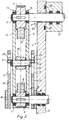
- a driving first shaft journal 1 and a driven second shaft journal 2 of a drive are each connected to drives, not shown, mounted in a rare frame 5. They each have at their ends shown in the drawings 1 and 2 a shaft-mounted toothed disk 3; 4 for engaging a closed toothed belt 6.
- a one-armed lever 7 is arranged, which is pivotally mounted with its first end 8 on the first shaft journal 1, for. B. in a swivel angle plus / minus alpha of 10 ° to a perpendicular center line 9.
- the second shaft journal 2 of the drive is arranged in a shaft guide 2 receiving, located at the second end 11 of the lever 7 longitudinal guide 12.
- the one-armed lever 7 can be made of parallel webs 13; 14 exist between which the shaft journals 1; 2 toothed lock washers 3; 4 are located. Approximately half the length of the lever 7 is a two-armed clamping lever 16, each with the same length of its arms 17; 18 rotatably mounted about an axis of rotation 19 of a pin 20 of the lever 7.
- the tension lever 16 carries at the free ends of its arms 17; 18 on bearing pin 21; 22 rotatably arranged clamping disks 23; 24.
- the tension discs 23; 24 are for Engagement of the toothed belt 6 is formed on its circumference as well as the toothed pulleys 3; 4.
- the ends of the arms 17; 18 can be used to receive the bearing bolts 21; 22 and the clamping washers 23; 24 be fork-shaped (Fig. 3).
- the clamping lever 16 has on its arms 17; 18 two guide pins 27 arranged symmetrically to the axis of rotation 19 of the pin 20; 28 on.
- the guide pin 27; 28 can be pressed into the clamping lever 16 and each protrude with their two ends 41; 42 and 43; 44 beyond the clear dimension of the profile of the clamping lever 16 (Fig. 2 and 3).
- the protruding ends 41; 42; 43; 44 the guide pin 27; 28 are supported on both sides of the clamping lever 16 each in identical internal curves 29 fixed to the frame; 31 from.
- the ends 41, 43 lie on the curves 29; 31 of a rare part 32 and the ends 42; 44 on curves 29; 31 of a parallel side part 33.
- the side parts 32; 33 e.g. B. in the form of side plates with trusses 34; 36 firmly connected.
- the shaft journal 2 protrudes through a slot 46 located in the horizontal direction in the side frame 5 and is mounted in a bearing housing 47 which is displaceably arranged on the side frame 5.
- the bearing housing 47 can, for. B. by means of linear guides 48; 49, e.g. B. dovetail guides and a drive, not shown, for. B. by means of rack and geared motor in the side frame 5 movable in the horizontal direction.
- the toothed belt tensioning device works as follows. If the drive with the shaft journal 2 and the toothed pulley 4 connected to it in the linear guide 48; 49 z. B. moved to the right in the direction of a horizontal line 37 (Fig. 1), the lever 7 as a result of the shaft journal 1 at an angle alpha of z. B. pivoted 10 ° to the right (maximum position). As a result of the horizontal movement of the shaft journal 2 and the resulting movement of the lever 7, the shaft journal 2 is moved in the longitudinal guide 12 in the direction of the second end 11 of the lever 7 until an end position A between the horizontal line 37 and the center line of the deflected lever 7 is reached (end position A is shown in Fig. 1).
- a drive can also consist of more than two drive elements.
- the swivel angle alpha of the lever 7 can be between zero and plus / minus 15 ° to the center line 9 (FIG. 1).
- the lever 7 can also pivot through an angle minus alpha to the center line 9 up to an end position B on the horizontal line 37, i. H. the axis of rotation 38 of the second shaft journal 2 is in said end position B (maximum deflection).
- the toothed belt tensioning device can also assume a different position than the position shown in FIG. 1.
- the shaft journals can be arranged on a horizontal or any other line.
- the driving and the driven shaft journal can be interchanged with one another compared to the illustration in FIGS. Not only the two end positions A and B are possible, but also any intermediate position of the shaft journal 2.
- the bearing bolts 21; 22 of the clamping discs 23; located at the ends of the clamping lever 16; 24 be formed eccentrically.
- the tensioning device according to the invention can also be used for tensioning other endless drive elements, e.g. B. for ropes, chains, V-belts or the like.
Landscapes
- Engineering & Computer Science (AREA)
- General Engineering & Computer Science (AREA)
- Mechanical Engineering (AREA)
- Devices For Conveying Motion By Means Of Endless Flexible Members (AREA)
Applications Claiming Priority (2)
| Application Number | Priority Date | Filing Date | Title |
|---|---|---|---|
| DE19944447017 DE4447017C1 (de) | 1994-12-30 | 1994-12-30 | Zahnriemenspanneinrichtung |
| DE4447017 | 1994-12-30 |
Publications (3)
| Publication Number | Publication Date |
|---|---|
| EP0719962A2 true EP0719962A2 (fr) | 1996-07-03 |
| EP0719962A3 EP0719962A3 (fr) | 1997-09-10 |
| EP0719962B1 EP0719962B1 (fr) | 1999-09-08 |
Family
ID=6537367
Family Applications (1)
| Application Number | Title | Priority Date | Filing Date |
|---|---|---|---|
| EP19950120222 Expired - Lifetime EP0719962B1 (fr) | 1994-12-30 | 1995-12-20 | Tendeur de courroie crantée |
Country Status (2)
| Country | Link |
|---|---|
| EP (1) | EP0719962B1 (fr) |
| DE (1) | DE4447017C1 (fr) |
Families Citing this family (1)
| Publication number | Priority date | Publication date | Assignee | Title |
|---|---|---|---|---|
| DE19926612A1 (de) * | 1999-06-11 | 2000-12-14 | Schaeffler Waelzlager Ohg | Riementrieb einer Brennkraftmaschine |
Family Cites Families (10)
| Publication number | Priority date | Publication date | Assignee | Title |
|---|---|---|---|---|
| DE319307C (de) * | 1918-04-27 | 1920-03-04 | Max Albrecht | Antriebsvorrichtung mit endlosem, selbsttaetig sich spannendem Treibmittel |
| DE614688C (de) * | 1929-11-27 | 1935-06-15 | Renold & Coventry Chain Co Ltd | Nachspannbarer Kettentrieb fuer den Nockenwellenantrieb von Brennkraftmaschinen |
| GB348939A (en) * | 1930-06-28 | 1931-05-21 | Frank Lincoln Morse | Improvements relating to chain drives |
| US3060760A (en) * | 1959-04-06 | 1962-10-30 | Joy Mfg Co | Chain tensioning device |
| US3888217A (en) * | 1973-09-24 | 1975-06-10 | Charles A Hisserich | Camshaft belt drive for variable valve timing |
| GB8712945D0 (en) * | 1987-06-25 | 1987-07-08 | Stidworthy F M | Variable valves |
| JPH02125141A (ja) * | 1988-11-04 | 1990-05-14 | Tokin Corp | 回転軸の位相角調整機構及び移動体の同期ずれ修正装置 |
| GB2228984B (en) * | 1989-03-08 | 1992-10-14 | Kliklok Corp | Rotary drive adjustment |
| US5316523A (en) * | 1991-09-25 | 1994-05-31 | Summagraphics N.V. | Sprocket control apparatus |
| US5362279A (en) * | 1993-08-05 | 1994-11-08 | Cms Gilbreth Packaging Systems | Self-tensioning chain drive |
-
1994
- 1994-12-30 DE DE19944447017 patent/DE4447017C1/de not_active Expired - Fee Related
-
1995
- 1995-12-20 EP EP19950120222 patent/EP0719962B1/fr not_active Expired - Lifetime
Also Published As
| Publication number | Publication date |
|---|---|
| EP0719962B1 (fr) | 1999-09-08 |
| EP0719962A3 (fr) | 1997-09-10 |
| DE4447017C1 (de) | 1996-03-07 |
Similar Documents
| Publication | Publication Date | Title |
|---|---|---|
| DE3937855C1 (fr) | ||
| DE9307391U1 (de) | Fachbildevorrichtung für eine Webmaschine | |
| EP0979170A1 (fr) | Element de glissiere variable en longueur pour chaine articulee | |
| EP0507198B1 (fr) | Chaîne à rouleaux pour le dispositif d'enfilement de bandes de papier d'une rotative à rouleaux | |
| WO2021148339A1 (fr) | Dispositif pour le support pivotant d'un rouleau de renvoi d'un dispositif transporteur à courroie, et dispositif transporteur à courroie équipé d'un tel dispositif | |
| DE4123476C2 (fr) | ||
| DE2110836C3 (de) | Vorrichtung für den Transport von Buchblöcken | |
| EP0060965A2 (fr) | Appareil de dressage de tôles | |
| EP0719962B1 (fr) | Tendeur de courroie crantée | |
| EP0777773B1 (fr) | Dispositif a lames | |
| EP0363939A1 (fr) | Transmission de conversion d'un mouvement rectiligne en un mouvement rotatif et inversement | |
| DE2419571C3 (de) | Vorrichtung zur Niederhaltung des Randbereiches von Blattmaterial auf einem Transportband | |
| DE19816563C1 (de) | Torantrieb | |
| EP3538730A1 (fr) | Dispositif d'entraînement pour un élément à entraîner | |
| DE4020148C2 (fr) | ||
| DE2725356C2 (de) | Vorrichtung zum Festhalten und Bewegen von textilen Bahnen | |
| DE2605510A1 (de) | Spannkette fuer gewebespannmaschinen | |
| DE2541542B2 (de) | Antriebssystem zum gemeinsamen antrieb von in reihe angeordneten wellen | |
| DE963015C (de) | Antriebsvorrichtung fuer die Fadenfuehrerschienen von flachen Kulierwirkmaschinen | |
| DE10105180C1 (de) | Ausstellvorrichtung für Ausstellfenster | |
| DE202004002756U1 (de) | Umlenkförderer | |
| AT345245B (de) | Vorrichtung zum bewegen von textilen bahnen | |
| DE1921691C (de) | Forderer mit einem endlosen Forderband | |
| DE9115549U1 (de) | Rollenkette für eine Papierbahneinzugsvorrichtung einer Rollenrotationsdruckmaschine | |
| DE1531815C (de) | Kettenförmige Vorrichtung mit veränderlicher Teilung zur Bewegung von Lasten |
Legal Events
| Date | Code | Title | Description |
|---|---|---|---|
| PUAI | Public reference made under article 153(3) epc to a published international application that has entered the european phase |
Free format text: ORIGINAL CODE: 0009012 |
|
| AK | Designated contracting states |
Kind code of ref document: A2 Designated state(s): CH FR GB IT LI SE |
|
| PUAL | Search report despatched |
Free format text: ORIGINAL CODE: 0009013 |
|
| AK | Designated contracting states |
Kind code of ref document: A3 Designated state(s): CH FR GB IT LI SE |
|
| 17P | Request for examination filed |
Effective date: 19980303 |
|
| RAP1 | Party data changed (applicant data changed or rights of an application transferred) |
Owner name: KOENIG & BAUER AKTIENGESELLSCHAFT |
|
| GRAG | Despatch of communication of intention to grant |
Free format text: ORIGINAL CODE: EPIDOS AGRA |
|
| GRAG | Despatch of communication of intention to grant |
Free format text: ORIGINAL CODE: EPIDOS AGRA |
|
| GRAH | Despatch of communication of intention to grant a patent |
Free format text: ORIGINAL CODE: EPIDOS IGRA |
|
| 17Q | First examination report despatched |
Effective date: 19990202 |
|
| GRAH | Despatch of communication of intention to grant a patent |
Free format text: ORIGINAL CODE: EPIDOS IGRA |
|
| GRAA | (expected) grant |
Free format text: ORIGINAL CODE: 0009210 |
|
| ITF | It: translation for a ep patent filed | ||
| AK | Designated contracting states |
Kind code of ref document: B1 Designated state(s): CH FR GB IT LI SE |
|
| REG | Reference to a national code |
Ref country code: CH Ref legal event code: EP |
|
| GBT | Gb: translation of ep patent filed (gb section 77(6)(a)/1977) |
Effective date: 19990916 |
|
| ET | Fr: translation filed | ||
| PLBE | No opposition filed within time limit |
Free format text: ORIGINAL CODE: 0009261 |
|
| STAA | Information on the status of an ep patent application or granted ep patent |
Free format text: STATUS: NO OPPOSITION FILED WITHIN TIME LIMIT |
|
| 26N | No opposition filed | ||
| PGFP | Annual fee paid to national office [announced via postgrant information from national office to epo] |
Ref country code: GB Payment date: 20011101 Year of fee payment: 7 |
|
| PGFP | Annual fee paid to national office [announced via postgrant information from national office to epo] |
Ref country code: FR Payment date: 20011220 Year of fee payment: 7 |
|
| PGFP | Annual fee paid to national office [announced via postgrant information from national office to epo] |
Ref country code: SE Payment date: 20011221 Year of fee payment: 7 |
|
| REG | Reference to a national code |
Ref country code: GB Ref legal event code: IF02 |
|
| PGFP | Annual fee paid to national office [announced via postgrant information from national office to epo] |
Ref country code: CH Payment date: 20020110 Year of fee payment: 7 |
|
| PG25 | Lapsed in a contracting state [announced via postgrant information from national office to epo] |
Ref country code: GB Free format text: LAPSE BECAUSE OF NON-PAYMENT OF DUE FEES Effective date: 20021220 |
|
| PG25 | Lapsed in a contracting state [announced via postgrant information from national office to epo] |
Ref country code: SE Free format text: LAPSE BECAUSE OF NON-PAYMENT OF DUE FEES Effective date: 20021221 |
|
| PG25 | Lapsed in a contracting state [announced via postgrant information from national office to epo] |
Ref country code: LI Free format text: LAPSE BECAUSE OF NON-PAYMENT OF DUE FEES Effective date: 20021231 Ref country code: CH Free format text: LAPSE BECAUSE OF NON-PAYMENT OF DUE FEES Effective date: 20021231 |
|
| EUG | Se: european patent has lapsed | ||
| GBPC | Gb: european patent ceased through non-payment of renewal fee |
Effective date: 20021220 |
|
| REG | Reference to a national code |
Ref country code: CH Ref legal event code: PL |
|
| PG25 | Lapsed in a contracting state [announced via postgrant information from national office to epo] |
Ref country code: FR Free format text: LAPSE BECAUSE OF NON-PAYMENT OF DUE FEES Effective date: 20030901 |
|
| REG | Reference to a national code |
Ref country code: FR Ref legal event code: ST |
|
| PG25 | Lapsed in a contracting state [announced via postgrant information from national office to epo] |
Ref country code: IT Free format text: LAPSE BECAUSE OF NON-PAYMENT OF DUE FEES;WARNING: LAPSES OF ITALIAN PATENTS WITH EFFECTIVE DATE BEFORE 2007 MAY HAVE OCCURRED AT ANY TIME BEFORE 2007. THE CORRECT EFFECTIVE DATE MAY BE DIFFERENT FROM THE ONE RECORDED. Effective date: 20051220 |