EP0719963B1 - Dispositif pour échanger des courroies sans fin - Google Patents
Dispositif pour échanger des courroies sans fin Download PDFInfo
- Publication number
- EP0719963B1 EP0719963B1 EP19950120223 EP95120223A EP0719963B1 EP 0719963 B1 EP0719963 B1 EP 0719963B1 EP 19950120223 EP19950120223 EP 19950120223 EP 95120223 A EP95120223 A EP 95120223A EP 0719963 B1 EP0719963 B1 EP 0719963B1
- Authority
- EP
- European Patent Office
- Prior art keywords
- disc
- frame
- bearing bush
- aperture
- shaft journal
- Prior art date
- Legal status (The legal status is an assumption and is not a legal conclusion. Google has not performed a legal analysis and makes no representation as to the accuracy of the status listed.)
- Expired - Lifetime
Links
- 230000037431 insertion Effects 0.000 description 3
- 238000003780 insertion Methods 0.000 description 3
- 238000005461 lubrication Methods 0.000 description 3
- 230000009286 beneficial effect Effects 0.000 description 1
- 210000000078 claw Anatomy 0.000 description 1
Images

Classifications
-
- F—MECHANICAL ENGINEERING; LIGHTING; HEATING; WEAPONS; BLASTING
- F16—ENGINEERING ELEMENTS AND UNITS; GENERAL MEASURES FOR PRODUCING AND MAINTAINING EFFECTIVE FUNCTIONING OF MACHINES OR INSTALLATIONS; THERMAL INSULATION IN GENERAL
- F16H—GEARING
- F16H7/00—Gearings for conveying rotary motion by endless flexible members
- F16H7/24—Equipment for mounting belts, ropes, or chains
Definitions
- the invention relates to a device for "threading" an endless traction device according to the generic term of claim 1 (US 2,678,565 A).
- US 26 78 565 A discloses an apparatus for Threading an endless belt onto a wheel one recess each in a frame and a wheel provided so that both recesses are common Can form an opening.
- the invention has for its object a Device for "threading” or “threading” a flexible endless traction device on a rod-shaped Creating bodies.
- an endless flexible traction means such as. B. a V-belt, a toothed belt, a rope or a conveyor belt with the device according to the invention can be done without removing any part.
- the rod-shaped body wrapped by the endless traction means e.g. B. a shaft journal or toothed belt wheel, etc. can be stored in the frame of the machine.
- the rod-shaped bodies mentioned can, however, also be arranged at such a small distance from the frame that the traction means cannot be guided through this distance.
- the endless traction device can be changed quickly, without special tools and without major machine downtimes.
- all endless flexible traction means such as. B. timing belts, chains, flat belts, etc. are placed around axes, drive shafts, spindles, cross beams, beams and the like.
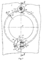
- a frame 1 has a bore 2.
- Hole 2 again has on its circumference 4 one in the frame 1 in axis-parallel direction to a rod-shaped body, e.g. B. a journal 6 of a cylinder 7, z. B. of a folder of a rotary printing press running continuous outer recess 8.
- a rod-shaped body e.g. B. a journal 6 of a cylinder 7, z. B. of a folder of a rotary printing press running continuous outer recess 8.
- annular disc e.g. B. in the form of a bearing bush 9 for receiving the Shaft journal 6 arranged. Its circumference is 11 one, in the axis-parallel direction to the shaft journal 6 extending, continuous inner recess 13.
- the disk or the bearing bush 9 can be used for the bore 2 are rotated so that both recesses 8; 13 lie one above the other and thus a common insertion channel or an opening 10 is created.
- Each recess 8; 13 is dimensioned in their cross-section so that they each one Run 14; 16 of an endless traction means 15, e.g. B. one Toothed belt 15 is adapted for a traction mechanism.
- the shaft journal 6 can be on both sides of the frame 1 each with a toothed belt pulley 17; 18 be provided the toothed belt pulley 18 on which the Traction means 15 is to be "threaded” between the frame 1 and the cylinder 7 is located.
- the "threading" and “threading” of the endless, from the first Run 14 and traction means consisting of second run 16 15 is described using a toothed belt 15:
- the endless toothed belt 15 becomes a loop with his molded first end through to one another Insertion channel 10 recesses 8; 13 approximately in the center towards the toothed belt pulley 18, d. H. in Stuck in the inaccessible side of the frame 1.
- the first strand 14 comes in the recess 13 of the Bearing bush 9 and the second strand 16 in the recess 8 the bore 2 to lie.
- the first strand 14 of the loop is taken along and 360 ° around the shaft journal 6 or the toothed belt pulley 18 placed.
- a "threading" of a toothed belt 15 or another Traction means take place in reverse order.
- the bearing bush 9 expediently has a ball bearing 19 on for mounting the shaft journal 6.
- the recesses 8; 13 preferably each have one semicircular cross section with approximately the same Area.
- the cross section of everyone Recess 8; 13 can also be U-shaped his. It is also possible for each recess 8; 13 in Cross-section dovetail-shaped. Further Cross-sectional shapes are possible.
- the bearing bush 9 expediently faces the Thickness of the frame 1 is larger by an amount a Length, from z. B. 10 mm.
- On the circumference 11 of the bearing bush 9 runs in the area of the amount a an annular groove 21 um, in which a fixable on the frame 1 Locking washer 22 engages. This will during the rotary movement a guide of the bearing bush 9 secured and an axial movement of the bearing bush 9 avoided.
- the locking washer 22 has an elongated hole 20 on. As a result, the locking washer 22 is radial Direction of the bearing bush 9 movable and can in a the groove 21 located recess 23 inserted become. So that the bearing bush 9 against one unintentional rotation locked.
- the stake other known securing means such. B. Clamping claws is possible.
- the insertion channel 10 can be closed on both sides be executed, e.g. B. with a locking bolt 24. Zur easy assembly and disassembly of such Lock bolt 24 and to prevent a unintentional falling out of this indicates one at the left end of the pin on one side of the circumference and semicircular collar 26.
- the collar 26 engages in a groove in the bearing bush 9 27 a.
- the groove 27 is located on the circumference 11 of the the frame 1 by the amount a protruding part of the Bearing bush 9 and is designed semi-circular, corresponding to the radius of the end of the locking bolt 24 located collar 26.
- the locking bolt 24 can by means of a through a bore in the collar 26 Screw fixed to frame 1 and thus against Be secured against twisting. In the case of using a Locking bolt 24 takes over at the same time a safety function against twisting the Bearing bush 9.
- a rotation of the bearing bush 9 when "opening" or “Threading” a toothed belt 15 can be done with a suitable tool, e.g. B. a detachable handle 28 take place, which in a on the bearing bushing 9th located radial bore 29 can be inserted.
- the Rotating the bearing bush 9 in the bore 2 of the Frame 1 is by the arrangement of the scope of Bearing bush 9 located lubrication grooves 31; 32 facilitated.
Landscapes
- Engineering & Computer Science (AREA)
- General Engineering & Computer Science (AREA)
- Mechanical Engineering (AREA)
- Pulleys (AREA)
- Devices For Conveying Motion By Means Of Endless Flexible Members (AREA)
Claims (5)
- Dispositif pour enfiler un moyen de traction (15) continu flexible sur une roue, un tourillon d'arbre ou analogue, dans un bâti (1) étant prévu un perçage (2), sur le bord duquel s'étend un premier évidement (8), en ce qu'à l'intérieur du perçage (2) est monté à rotation un disque (9) sur le contour extérieur (11) duquel s'étend un deuxième évidement (13), si bien que les deux évidements (8; 13) peuvent constituer une ouverture commune (10), dans laquelle le moyen de traction (15), se présentant sous la forme d'une boucle continue, est introduit depuis un côté, boucle dont un tronçon (16) est fixé dans l'évidement (8) fixe par rapport au bâti, tandis que l'autre tronçon (14) est placé dans l'évidement (13) du disque (9), grâce à la rotation de celui-ci est tourné de 360 degrés et entraíné, et est passé autour de la roue, du tourillon d'arbre (6) ou analogue, afin d'être ainsi placé en appui, caractérisé en ce qu'un moyen de sécurité (22; 24) susceptible d'être fixé sur le bâti (1), coopérant avec le disque (9), est disposé pour empêcher toute rotation du disque (9).
- Dispositif selon la revendication 1, caractérisé en ce que le moyen de sécurité (24) est réalisé sous la forme de boulon de fermeture (24) et en ce que l'ouverture commune (10) est susceptible d'être obturée au moyen du boulon de fermeture (24).
- Dispositif selon la revendication 1, caractérisé en ce que le disque (9) est doté d'un dépassement (a) et d'une gorge de pourtour (21), dans laquelle s'engage un disque ou rondelle de sécurité (22) monté(e) de façon excentrée et disposé(e) de façon à être susceptible d'être inséré(e) dans un creusement (23) ménagé dans la gorge (21).
- Dispositif selon la revendication 1, caractérisé en ce que le disque (9) est réalisé sous la forme de deux coussinets de palier.
- Dispositif selon la revendication 1, caractérisé en ce que le disque (9) est réalisé sous la forme de bague extérieure d'un roulement à billes.
Applications Claiming Priority (2)
| Application Number | Priority Date | Filing Date | Title |
|---|---|---|---|
| DE19944447202 DE4447202C1 (de) | 1994-12-30 | 1994-12-30 | Vorrichtung zum Wechseln eines endlosen Zugmittels |
| DE4447202 | 1994-12-30 |
Publications (3)
| Publication Number | Publication Date |
|---|---|
| EP0719963A2 EP0719963A2 (fr) | 1996-07-03 |
| EP0719963A3 EP0719963A3 (fr) | 1997-07-23 |
| EP0719963B1 true EP0719963B1 (fr) | 2000-03-15 |
Family
ID=6537484
Family Applications (1)
| Application Number | Title | Priority Date | Filing Date |
|---|---|---|---|
| EP19950120223 Expired - Lifetime EP0719963B1 (fr) | 1994-12-30 | 1995-12-20 | Dispositif pour échanger des courroies sans fin |
Country Status (2)
| Country | Link |
|---|---|
| EP (1) | EP0719963B1 (fr) |
| DE (1) | DE4447202C1 (fr) |
Family Cites Families (1)
| Publication number | Priority date | Publication date | Assignee | Title |
|---|---|---|---|---|
| US2678565A (en) * | 1951-12-11 | 1954-05-18 | Hoe & Co R | Mechanism for replacing endless belts |
-
1994
- 1994-12-30 DE DE19944447202 patent/DE4447202C1/de not_active Expired - Fee Related
-
1995
- 1995-12-20 EP EP19950120223 patent/EP0719963B1/fr not_active Expired - Lifetime
Also Published As
| Publication number | Publication date |
|---|---|
| DE4447202C1 (de) | 1996-03-21 |
| EP0719963A3 (fr) | 1997-07-23 |
| EP0719963A2 (fr) | 1996-07-03 |
Similar Documents
| Publication | Publication Date | Title |
|---|---|---|
| DE4009968C2 (de) | Planetenradträgeranordnung für Planetengetriebesystem | |
| EP1132651B1 (fr) | Entraínement fileté à éléments de roulement | |
| DE69122172T2 (de) | Geteilte Zahnradvorrichtung | |
| DE3990222B4 (de) | Raupenfahrwerk | |
| DE3700968A1 (de) | Spanneinrichtung zum axialen festspannen eines werkzeuges, insbesondere einer scheibe | |
| DE69602514T2 (de) | Verbesserungen in und bezüglich auf Fahrrad-Antriebsanordnungen | |
| DE2531214C2 (de) | Schraubenschlüssel in Form eines Spannfutters | |
| DE2528173A1 (de) | Vorrichtung zur uebertragung einer antriebskraft | |
| DE102007039522B4 (de) | Vorrichtung an einem Streckwerk einer Strecke für Textilfaserbänder | |
| DE19543987A1 (de) | Kolbenmechanismus, Motor oder Pumpe, der mit Stützrollen auf einer Nocke versehen ist | |
| DE3613987A1 (de) | Vorrichtung zum loesbaren befestigen einer schleifscheibe | |
| DE2740484A1 (de) | V- oder keilriemen-scheibe | |
| DE69914755T2 (de) | Maschine mit Rollen und mit Schnellverbindungssystem zum Lagern von Rollen | |
| DE2726080C2 (de) | Anordnung zum Verschieben eines Wälzlagers in beiden axialen Richtungen | |
| DE3439668A1 (de) | Schluesselloses schnellspannfutter | |
| DE7628768U1 (de) | Hebezeug | |
| DE2530052A1 (de) | Kupplung zum drehfesten verbinden einander zugeordneter abschnitte einer lieferwelle fuer textilmaschinen | |
| EP0719963B1 (fr) | Dispositif pour échanger des courroies sans fin | |
| DE1491029A1 (de) | Zahnaertzliches Handstueck | |
| DE3811970A1 (de) | Waelzlageranordnung | |
| EP0662061A1 (fr) | Palier de pedalier pour bicyclettes, exerciseurs et instruments similaires | |
| DE102016201100B4 (de) | Gleitlagerring und Aktuator mit Gleitlagerring | |
| DE3712159A1 (de) | Hinterer umwerfer fuer ein fahrrad | |
| DE10234210A1 (de) | Verbindung zweier Maschinenteile | |
| DE3318745C2 (de) | Hobelmaschine, insbesondere Handhobel |
Legal Events
| Date | Code | Title | Description |
|---|---|---|---|
| PUAI | Public reference made under article 153(3) epc to a published international application that has entered the european phase |
Free format text: ORIGINAL CODE: 0009012 |
|
| AK | Designated contracting states |
Kind code of ref document: A2 Designated state(s): CH FR GB IT LI SE |
|
| PUAL | Search report despatched |
Free format text: ORIGINAL CODE: 0009013 |
|
| AK | Designated contracting states |
Kind code of ref document: A3 Designated state(s): CH FR GB IT LI SE |
|
| 17P | Request for examination filed |
Effective date: 19980114 |
|
| RAP1 | Party data changed (applicant data changed or rights of an application transferred) |
Owner name: KOENIG & BAUER AKTIENGESELLSCHAFT |
|
| 17Q | First examination report despatched |
Effective date: 19981123 |
|
| GRAG | Despatch of communication of intention to grant |
Free format text: ORIGINAL CODE: EPIDOS AGRA |
|
| GRAG | Despatch of communication of intention to grant |
Free format text: ORIGINAL CODE: EPIDOS AGRA |
|
| GRAH | Despatch of communication of intention to grant a patent |
Free format text: ORIGINAL CODE: EPIDOS IGRA |
|
| GRAH | Despatch of communication of intention to grant a patent |
Free format text: ORIGINAL CODE: EPIDOS IGRA |
|
| GRAA | (expected) grant |
Free format text: ORIGINAL CODE: 0009210 |
|
| AK | Designated contracting states |
Kind code of ref document: B1 Designated state(s): CH FR GB IT LI SE |
|
| PG25 | Lapsed in a contracting state [announced via postgrant information from national office to epo] |
Ref country code: SE Free format text: THE PATENT HAS BEEN ANNULLED BY A DECISION OF A NATIONAL AUTHORITY Effective date: 20000315 |
|
| REG | Reference to a national code |
Ref country code: CH Ref legal event code: EP |
|
| ITF | It: translation for a ep patent filed | ||
| GBT | Gb: translation of ep patent filed (gb section 77(6)(a)/1977) |
Effective date: 20000315 |
|
| ET | Fr: translation filed | ||
| PLBE | No opposition filed within time limit |
Free format text: ORIGINAL CODE: 0009261 |
|
| STAA | Information on the status of an ep patent application or granted ep patent |
Free format text: STATUS: NO OPPOSITION FILED WITHIN TIME LIMIT |
|
| 26N | No opposition filed | ||
| PGFP | Annual fee paid to national office [announced via postgrant information from national office to epo] |
Ref country code: GB Payment date: 20011101 Year of fee payment: 7 |
|
| PGFP | Annual fee paid to national office [announced via postgrant information from national office to epo] |
Ref country code: FR Payment date: 20011220 Year of fee payment: 7 |
|
| REG | Reference to a national code |
Ref country code: GB Ref legal event code: IF02 |
|
| PGFP | Annual fee paid to national office [announced via postgrant information from national office to epo] |
Ref country code: CH Payment date: 20020110 Year of fee payment: 7 |
|
| PG25 | Lapsed in a contracting state [announced via postgrant information from national office to epo] |
Ref country code: GB Free format text: LAPSE BECAUSE OF NON-PAYMENT OF DUE FEES Effective date: 20021220 |
|
| PG25 | Lapsed in a contracting state [announced via postgrant information from national office to epo] |
Ref country code: LI Free format text: LAPSE BECAUSE OF NON-PAYMENT OF DUE FEES Effective date: 20021231 Ref country code: CH Free format text: LAPSE BECAUSE OF NON-PAYMENT OF DUE FEES Effective date: 20021231 |
|
| GBPC | Gb: european patent ceased through non-payment of renewal fee |
Effective date: 20021220 |
|
| REG | Reference to a national code |
Ref country code: CH Ref legal event code: PL |
|
| PG25 | Lapsed in a contracting state [announced via postgrant information from national office to epo] |
Ref country code: FR Free format text: LAPSE BECAUSE OF NON-PAYMENT OF DUE FEES Effective date: 20030901 |
|
| REG | Reference to a national code |
Ref country code: FR Ref legal event code: ST |
|
| PG25 | Lapsed in a contracting state [announced via postgrant information from national office to epo] |
Ref country code: IT Free format text: LAPSE BECAUSE OF NON-PAYMENT OF DUE FEES;WARNING: LAPSES OF ITALIAN PATENTS WITH EFFECTIVE DATE BEFORE 2007 MAY HAVE OCCURRED AT ANY TIME BEFORE 2007. THE CORRECT EFFECTIVE DATE MAY BE DIFFERENT FROM THE ONE RECORDED. Effective date: 20051220 |