EP0719998A2 - Automatische oder halbautomatische Schusswaffe - Google Patents
Automatische oder halbautomatische Schusswaffe Download PDFInfo
- Publication number
- EP0719998A2 EP0719998A2 EP96103610A EP96103610A EP0719998A2 EP 0719998 A2 EP0719998 A2 EP 0719998A2 EP 96103610 A EP96103610 A EP 96103610A EP 96103610 A EP96103610 A EP 96103610A EP 0719998 A2 EP0719998 A2 EP 0719998A2
- Authority
- EP
- European Patent Office
- Prior art keywords
- magazine
- cartridge
- carcass
- retainer
- spring
- Prior art date
- Legal status (The legal status is an assumption and is not a legal conclusion. Google has not performed a legal analysis and makes no representation as to the accuracy of the status listed.)
- Withdrawn
Links
Images


Classifications
-
- F—MECHANICAL ENGINEERING; LIGHTING; HEATING; WEAPONS; BLASTING
- F41—WEAPONS
- F41A—FUNCTIONAL FEATURES OR DETAILS COMMON TO BOTH SMALLARMS AND ORDNANCE, e.g. CANNONS; MOUNTINGS FOR SMALLARMS OR ORDNANCE
- F41A17/00—Safety arrangements, e.g. safeties
- F41A17/34—Magazine safeties
- F41A17/38—Magazine mountings, e.g. for locking the magazine in the gun
-
- F—MECHANICAL ENGINEERING; LIGHTING; HEATING; WEAPONS; BLASTING
- F41—WEAPONS
- F41A—FUNCTIONAL FEATURES OR DETAILS COMMON TO BOTH SMALLARMS AND ORDNANCE, e.g. CANNONS; MOUNTINGS FOR SMALLARMS OR ORDNANCE
- F41A9/00—Feeding or loading of ammunition; Magazines; Guiding means for the extracting of cartridges
- F41A9/59—Ejectors for clips or magazines, e.g. when empty
Definitions
- the subject of the present invention is an automatic or semi-automatic firearm comprising a carcass, a cartridge magazine removable in the carcass, a movable cartridge lift piston in the magazine, a spring in the magazine for raising the lift piston by pressure.
- permanent, temporary retention of the magazine in the carcass activated by engagement in a notch on the wall of the latter, manual control to deactivate the retention of the magazine at will, a barrel near the carcass, a fire chamber, a movable breech by reciprocating on the carcass comprising means for ensuring the insertion of the cartridges from the store to the fire chamber and the extraction of the casings of the drawn cartridges, and an automatic device for ejecting the store out of the carcass comprising a magazine retaining actuation finger associated with the cartridge lifting piston, linked to the height movement of the latter and placed in a ne position provided to meet and deactivate the magazine retainer under the pressure of a spring, at the earliest during the movement of the last cartridge of the magazine by the movable cylinder
- means are provided to facilitate and make easy the manipulations of the shooter necessary for the evacuation and replacement of a cartridge magazine, for checking the number of cartridges remaining in its magazine, as well as to warn it of the exhaustion of these, after firing the last cartridge.
- These means include retaining the magazine for cartridges and its deactivation command already indicated and, on many of these known weapons, a breech stopper, a mechanism suitable for retaining the breech open, in the retracted position, after the firing of the last cartridge of the shop.
- the retention of the cartridge magazine is constituted by a lever having a stop coming to engage, under the permanent pressure of a spring, in a retaining notch of the magazine wall and this at the arrival of the magazine in place provided in the carcass.
- the command to deactivate the magazine retainer is generally constituted by a simple extension of the lever of this retainer outside the carcass and having at its end a grip for the thumb or forefinger of the shooter, in particular when this control is placed in the immediate environment of the trigger of the weapon, at the top of the butt, for reasons of ergonomics.
- the stop of the latter is disengaged from the notch of the magazine, and the latter is released and can be removed from the carcass.
- the shooter can thus at any time extract the magazine from his weapon, not only to control the number of cartridges remaining or to replace it with another one but also for security reasons, such as for example in the event of a shooting stoppage or in the event of the weapon being engaged.
- the breech stop is a return spring lever comprising a stop intended to engage in a retaining notch of the movable breech to keep the latter open in the retracted position.
- the engagement of the stop in the bolt retaining notch is conditioned on the one hand and firstly by application of the thrust of the cartridge lifting piston on the cylinder head retainer after chambering of the last cartridge of the magazine in the fire chamber, and on the other hand and in a second step by penetration of this stop, and under the effect of this thrust, in the retaining notch of the movable cylinder head, a little before the end of the recoil movement of the latter following the firing of the last cartridge.
- the fact that the bolt remains open in the recoil position avoids the shooter having to count the shots to know when he reaches the end of the cartridge magazine, allows in the shooting range the visual verification at distance that the weapon is quite empty and out of function, and also avoids the shooter being with the breech turned down and the weapon ready to fire on an empty fire chamber, awkward situation in precision shooting and certainly delicate in combat.
- the fact that the breech remains open can contribute to cooling the barrel.
- the shooter moves the bolt a little further until the end of its recoil stroke to release the stop of the bolt retainer from the retaining notch thereof, which s 'erased under the effect of the return spring, and lets the bolt start again to introduce the first cartridge from this magazine into the fire chamber, the weapon thus being again ready to fire.
- means are provided so that the installation of a new magazine triggers the return of the bolt which remains open after the firing of the last cartridge from the previous magazine, and thus causes the chambering of the first cartridge from this new store.
- the shooter is thus freed from the need to manipulate the breech to chamber this first cartridge, and he only has to take care of deactivating the retention of the empty magazine before replacing it with a new magazine.
- the shooter is released from the need to manipulate the command to deactivate the retention of an empty magazine before it can be replaced, since it is automatically ejected during the movement of its last cartridge by the movable bolt, during the return of the latter ci following the firing of the penultimate cartridge.
- this device is provided in addition to the manual control to deactivate the magazine retainer, the latter is always ready to operate and the shooter does not lose the possibility of removing the magazine at any time and for some reason whether it be.
- the last cartridge of the ejected magazine being introduced into the fire chamber by the movable breech, this means that during the introduction of the new magazine, a cartridge is chambered and the weapon ready to fire with it.
- the movable breech can never close on an empty cartridge fire chamber, which is to be feared on current known weapons which would not be equipped with '' breech retainer, and the visual signaling effect of the arrival at the end of the magazine is not eliminated, since this effect is here provided by the ejection of the empty magazine ... on a weapon however ready to fire !
- the object of the invention is to further minimize the handicaps inherent in the manipulations required by the operations of changing the magazine of cartridges of a firearm and, at the same time, to increase the firepower of this weapon.
- the invention conforms to the definitions given by the claims.
- the firearm represented by the six figures 1 to 6 of the first embodiment is a semi-automatic pistol operating without a breech retainer, but it is obvious that its inventive characters are applicable to any other type of weapon automatic or semi-automatic, whether or not fitted with a cylinder head retainer.
- This weapon comprises a carcass 1 forming a stock 2, a trigger guard 3 of a trigger 4 and a movable breech 6.
- the cartridge magazine 8 comprises a cartridge lifting piston 19 subjected to the permanent pressure of a compression spring 20 bearing on the bottom of said magazine.
- the cylinder head 6, movable back and forth on the carcass 1, comprises the usual means for, after each shot of a cartridge, extract from the fire chamber and during its retraction the socket of the drawn cartridge, and move then introduce during its return another cartridge from the magazine 8 to the fire chamber 10, and this until the last cartridge, at the end of the height stroke of the lifting piston 19.
- a support ramp 23 of the cartridge emerging from the magazine 8 and a front wall 24 of the breech 6 intended to intercept this cartridge and to transfer it into the fire chamber 10 after the breech 6 recedes subsequent to firing and during its return . From the front wall 24 opens the firing pin of the cartridge, not shown.
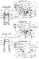
- the gun is ready to fire the penultimate cartridge 11, already introduced into the fire chamber 10, and the last cartridge 12 of the magazine 8 is pressed by the lifting piston 19 and under the pressure of the spring 20 against the ramp 23 of the movable yoke 6.
- the phase represented by FIGS. 2 and 5, which is consecutive to the firing of the penultimate cartridge 11, is that during which the last cartridge 12 is moved and being introduced into the fire chamber 10, by return from the cylinder head 6, just after the finger 25 of the cartridge lifting piston 19 meets the tooth 16 of the retainer 13 of the cartridge magazine 8, the latter still being retained by this tooth 16. It is noted here in passing that the inclination of the active end of the wedge-shaped finger 25 is identical to that of the face of the tooth 16 urged by this finger. But this is not essential and contact can be made on an angle or on a rounding of tooth 16.
- the spring 20 is still armed on a stroke in residual height and it pushes thereby and by reaction down the cartridge magazine 8.
- the relative positions of the finger 25 of the lifting piston and the notch 17 for retaining the magazine, as well as the ratio of the forces of the springs 18 and 20 are determined so that the magazine 8 is released from its retention by the finger 25 a little before the end of the height stroke of the cartridge lifting piston 19 and while the latter is still in contact with the cartridge 12, during the transfer of the latter.
- the retainer 13 is again armed by its spring 18, ready to retain a new cartridge magazine, while the last cartridge 12 is chambered and ready to be drawn.
- the chambering of the first cartridge of the new magazine is then done automatically after the cartridge 12 has been fired, on the return of the movable cylinder head 6, without there being any need to manipulate the latter.
- the automatic cartridge magazine ejection device While retaining the basic characteristics of the automatic cartridge magazine ejection device, it is possible to apply it to a weapon fitted with a breech catch when the thing is deemed useful, as for example in the use of the weapon in a shooting range and for a question of safety, or cooling of the barrel, and this without need for appropriations of the breech retainer.
- the weapon shown here as an example is also a semi-automatic pistol, but which was chosen for its differences in structure.
- the differences in the structure of the weapon here relate, in addition to the presence of a bolt retainer, to the conformation of the retainer of the cartridge magazine and of the cartridge lifting piston.
- the carcass 27 comprises a breech retainer 28 in the form of a lever articulated on a pivot and having at its end a stop 30 intended to block the movable breech 60 in the retracted position by engagement in a notch of that -ci which is here formed by the rise of the ramp 31 forming the front closure wall 32 of this movable yoke.
- the breech retainer 28 In the intermediate position, between the pivot of the retainer 28 and the stop 30, the breech retainer 28 has a stop 33 arranged in the path of a plunger 34 integral with the cartridge lift piston 190 to be urged by the thrust of the latter, under the effect of its lifting spring 20, after chambering the last cartridge 12 of the magazine, against a return spring 35.
- a stop 36, integral with the carcass 27, defines the position non-active rest of the cylinder head retainer 28.
- the retainer of the cartridge magazine 80 which here bears the reference 130, is a lever articulated on the carcass 27, activated by a compression spring 180, and having a retaining tooth 160 intended to snap, under the thrust of said spring, into a retaining notch 170 of the cartridge magazine 80.
- the manual control of this retainer 130 is constituted here by an extension 150 of this retainer having a grip for the shooter's finger.
- the automatic cartridge magazine ejection device 80 here comprises a finger 250 for actuating the retainer 130 of the cartridge magazine mounted movable by translation in the cartridge lifting piston 190, in the transverse direction thereof and pressed elastically by a compression spring 37 against the wall of the cartridge magazine 80.
- This wall has a hole 38, placed opposite the tooth 160 of the retainer 130 in the immediate environment of the retainer notch 170 to allow passage for the finger 250 d actuation of the retainer 130 at the arrival of this finger at this hole.
- the cartridge magazine 80 also has here a projecting lateral support 39 intended to be stressed by the push of a spring 40 during the introduction of said magazine into the carcass 27 and before the activation of the retainer 130 of the latter, the active end of the spring 40 being for this purpose disposed in the path of movement of the lateral support 39.
- the spring 40 here acts as an arming spring for the automatic ejection device from the cartridge magazine, as will be shown.
- FIGS. 7, 8 and 9 The operation of this second embodiment, illustrated by FIGS. 7, 8 and 9, is as follows:
- the gun is ready to draw the last cartridge 12 from magazine 80, already inserted in fire chamber 10.
- the cylinder head stopper 28 is subjected to the pressure of the spring 20 by pushing the pusher 34 of the cartridge lifting piston 190 on its stop 33 against the return spring 35, and the stop 30 abuts against the ramp 31 .
- the finger 250 of the cartridge lifting piston 190 is inactive, in abutment against the wall of the magazine 80, and the latter is held in place by the tooth 160 of the retainer 130 engaged in the notch 170.
- the movable breech 60 arrives at the end of the recoil stroke, the ramp 31 disappears from above the stop 30 of the breech stop 28 and the latter , released and still subject to the pressure of the spring 20 of the cartridge lifting piston 190, pivots anti-clockwise and engages said stop 30 in the notch formed by the ascent of the ramp 31, in front of the front wall 32 .
- the cartridge magazine 80 released from its retainer, is ejected from the carcass 27 by the spring 40 while the breech retainer 28, recalled by the return spring 35, begins to return to its position of rest against the stop 36 but is stopped before the end of this movement by the simultaneous return of the cylinder head 60 which causes the stop 30 to meet the front face 32.
- FIGS. 10 and 11 This possibility, illustrated by FIGS. 10 and 11, is shown applied to a weapon, the breech retainer of which consists of a lateral stop 41, movable by translation in the transverse direction of the weapon, mounted on a slide 42 guided in two lateral slides of the walls of the carcass 43 and armed by a leaf spring 44, to engage in a notch 45 of the movable yoke 46 at the arrival of the latter in the retracted position.
- the lateral stop 41 is secured to a contact finger 47, offset in the longitudinal direction of the cylinder head 46, passing through the side wall of the carcass 43 at the level of the cartridge magazine housing 48, and comprising an inclined contact end intended to be stressed by the thrust of the inclined upper wall of the cartridge magazine 48, by wedge effect, when the latter is put into place in its housing, against the spring 44, as can be seen in FIG. 10 .
- the cartridge magazine 48 still contains its last cartridge 12, while the penultimate is chambered, ready to be pulled, and this magazine is retained in its housing, as for example on the Figure 1 of the first embodiment.
- the stop 41 of the breech retainer is released from the path of the notch 45 of the movable breech 46 by retaining its contact finger 47 bearing on the magazine 48.
- FIGS. 12 to 16 makes it possible to obtain the same effect as in the first embodiment, but here with a retainer 131 of the cartridge magazine constituted by a lateral lever integrating in its structure a stop drive 252 associated with a retaining tooth 161, these two elements being spaced from one another.
- the retainer 131 of the cartridge magazine 81 is for example of triangular profile having at its lower apex an axis of articulation 481, at its upper right apex, on the side of the magazine 81, a finger parallel to this axis forming the stop d drive 252 already mentioned, and at its third apex a knurled button 49 for manual control.
- the retaining tooth 161 Between the hinge pin 481 and the drive stop 252 is located the retaining tooth 161, in an offset position towards the front of the weapon relative to a notional plane joining the hinge pin 481 to the axis of the drive stop 252, in order to facilitate its release from a retaining notch 171 from the wall of the cartridge magazine 81 during the automatic ejection action.
- a spring 51 for actuating the retaining 131 of the magazine intended to engage this tooth in the retaining notch 171 of the cartridge magazine when it is placed in the weapon.
- the cartridge magazine 81 has a vertical notch 50 in its two side walls adjoining its wall rounded front, in one of which engages the stop 252 of the retaining lever 131 when it is placed in the weapon, which is made clearly visible in FIG. 15.
- the cartridge lifting piston 191 here comprises a finger 251 for actuating the retainer 131 formed by a return from its upper wall constituting a pallet intended to come to meet the drive stop 252 of said retainer 131 before arriving at the end of stroke of its ascent in store 81, in the configuration shown in FIG. 13.
- the automatic ejection of the cartridge magazine 81 takes place here according to the same sequences as in the first embodiment.
- This automatic ejection takes place during the transfer of the last cartridge 12, from the magazine 81 to the fire chamber 10, in a position immediately following that shown in FIG. 13 and while the cartridge elevator 191 is still supported on this cartridge and still undergoes spring pressure 20.
- the drive finger 251 of the cartridge elevator 191 pushes up the drive stop 252 of the retainer 131, which has the effect of pivoting this retaining around its axis 481 and against its spring 51 and releasing its retaining tooth 161 from the retaining notch 171 of the cartridge magazine 81.
- This third embodiment is simple and very reliable in that it does not require too fine fine adjustment. It advantageously applies to weapons in which sufficient space can be reserved for the installation of a stopper 131 of the type described between the housing of the cartridge magazine and the trigger.
- the activation of the automatic ejection of the cartridge magazine may include only one specifically suitable spring, such as the spring 40 of the second embodiment, use an existing spring, such as the spring 20 of the magazine. cartridges of the first and third embodiments, or even a combination of these two systems.
- the movable finger 250 can be mounted, not inside the lifting piston 190, but outside of it, for example by end of a spring leaf fixed to said piston. It is also possible to fix this finger 250 directly to the piston 190 in the active protruding position, in which case a groove will be provided in the carcass to allow its displacement in height with the piston 190.
Landscapes
- Engineering & Computer Science (AREA)
- General Engineering & Computer Science (AREA)
- Toys (AREA)
- Portable Nailing Machines And Staplers (AREA)
- Packaging Of Annular Or Rod-Shaped Articles, Wearing Apparel, Cassettes, Or The Like (AREA)
- Vending Machines For Individual Products (AREA)
- Radar Systems Or Details Thereof (AREA)
Applications Claiming Priority (3)
| Application Number | Priority Date | Filing Date | Title |
|---|---|---|---|
| CH96492A CH686154A5 (fr) | 1992-03-26 | 1992-03-26 | Arme a feu automatique ou semi-automatique. |
| CH964/92 | 1992-03-26 | ||
| EP93103856A EP0562364B1 (de) | 1992-03-26 | 1993-03-10 | Automatische oder halbautomatische Schusswaffe |
Related Parent Applications (2)
| Application Number | Title | Priority Date | Filing Date |
|---|---|---|---|
| EP93103856.6 Division | 1993-03-10 | ||
| EP93103856A Division EP0562364B1 (de) | 1992-03-26 | 1993-03-10 | Automatische oder halbautomatische Schusswaffe |
Publications (2)
| Publication Number | Publication Date |
|---|---|
| EP0719998A2 true EP0719998A2 (de) | 1996-07-03 |
| EP0719998A3 EP0719998A3 (de) | 1996-07-10 |
Family
ID=4199289
Family Applications (2)
| Application Number | Title | Priority Date | Filing Date |
|---|---|---|---|
| EP96103610A Withdrawn EP0719998A3 (de) | 1992-03-26 | 1993-03-10 | Automatische oder halbautomatische Schusswaffe |
| EP93103856A Expired - Lifetime EP0562364B1 (de) | 1992-03-26 | 1993-03-10 | Automatische oder halbautomatische Schusswaffe |
Family Applications After (1)
| Application Number | Title | Priority Date | Filing Date |
|---|---|---|---|
| EP93103856A Expired - Lifetime EP0562364B1 (de) | 1992-03-26 | 1993-03-10 | Automatische oder halbautomatische Schusswaffe |
Country Status (5)
| Country | Link |
|---|---|
| US (3) | US5379541A (de) |
| EP (2) | EP0719998A3 (de) |
| AT (1) | ATE153438T1 (de) |
| CH (1) | CH686154A5 (de) |
| DE (1) | DE69310792D1 (de) |
Families Citing this family (30)
| Publication number | Priority date | Publication date | Assignee | Title |
|---|---|---|---|---|
| US5638626A (en) * | 1996-04-25 | 1997-06-17 | Westrom; Mark | Ammunition magazine |
| US6027431A (en) * | 1997-04-26 | 2000-02-22 | Stearns; Kenneth W. | Exercise methods and apparatus with an adjustable crank |
| DE19732656C2 (de) * | 1997-07-29 | 2001-01-11 | Sig Schweiz Industrieges | Magazinhalter an einer Pistole |
| DE19800620A1 (de) * | 1998-01-12 | 1999-07-15 | Lars Malindretos | Automatischer Magazinauswurf für Handfeuerwaffen (Lang- und Kurzwaffen) |
| USD428101S (en) * | 1998-07-10 | 2000-07-11 | Sig Arms International Ag | Magazine release catch for a pistol |
| US6070352A (en) * | 1998-11-12 | 2000-06-06 | Colt's Manufacturing Company, Inc. | Firearm magazine cartridge converter |
| DE10296851T5 (de) * | 2001-05-24 | 2004-04-29 | Greenhut, Paul Morris, Hartford | Patronenkammersystem für Schusswaffen |
| US8079356B2 (en) * | 2002-02-07 | 2011-12-20 | James Patrick Reible | Pneumatic projectile launching apparatus with partition-loading apparatus |
| US6606811B1 (en) * | 2002-10-09 | 2003-08-19 | Knight Armament Company | Firearm magazine with improved bolt catch actuator |
| US7261029B1 (en) | 2006-05-02 | 2007-08-28 | Davis Douglas P | Firearm bolt locking mechanism |
| US8122632B2 (en) * | 2009-11-05 | 2012-02-28 | Krow Innovation, Llc | Dynamic magazine latch |
| RU2433369C1 (ru) * | 2010-04-29 | 2011-11-10 | Общество с ограниченной ответственностью "АВТЭКС" | Стрелковое оружие повышенной безопасности и скорострельности |
| US8104209B1 (en) | 2011-02-03 | 2012-01-31 | Krow Innovation, Inc. | Dynamic latch for a tube mounted magazine well |
| EP2788706A4 (de) * | 2011-12-08 | 2015-06-24 | Sturm Ruger & Co | Magazin für eine feuerwaffe |
| US9097474B1 (en) * | 2012-04-24 | 2015-08-04 | Cabot Intellectual Property Holdings | Semiautomatic firearm |
| RU2596261C2 (ru) * | 2013-10-16 | 2016-09-10 | Альберт Фаридович Гайнутдинов | Автоматически отделяемый магазин |
| RU2548285C1 (ru) * | 2014-02-21 | 2015-04-20 | Открытое акционерное общество "Концерн "Калашников" | Манипулятор сброса магазина стрелкового оружия |
| US10612876B2 (en) | 2014-08-18 | 2020-04-07 | Kmm Engineering, Inc. | Adjustable force replaceable slide notch system |
| US10175014B2 (en) * | 2014-08-18 | 2019-01-08 | Mettlegun, Llc | Firearm loading system |
| US9568263B1 (en) * | 2015-01-07 | 2017-02-14 | Daniel G. O'Kelly | Self-loading firearm with automatic slide and magazine catch and release |
| US20160348992A1 (en) * | 2015-05-29 | 2016-12-01 | Richard J. Tisone | Ammunition magazine configured for automatic ejection |
| US10018438B2 (en) * | 2015-11-19 | 2018-07-10 | Clipfort L.T.D Bv | Device and method for blocking discharge in firearms |
| TWM551263U (zh) * | 2017-02-24 | 2017-11-01 | Guay Guay Trading Co Ltd | 彈匣主動脫離結構 |
| US10563941B2 (en) * | 2018-02-20 | 2020-02-18 | Fei Chen | Auto-releasing method and arrangement of detachable magazine for firearm |
| RU185899U1 (ru) * | 2018-08-29 | 2018-12-21 | Межрегиональное общественное учреждение "Институт инженерной физики" | Устройство для сброса магазина |
| DE202018106506U1 (de) | 2018-10-30 | 2018-11-26 | Viktor Schatz | Handfeuerwaffe mit Anzeige letzter Patrone |
| US11143474B2 (en) | 2019-02-04 | 2021-10-12 | Ruben Maldonado | Magazine with automatic ejection and breech detection |
| EP4587775A1 (de) * | 2022-09-13 | 2025-07-23 | Henry Rac Holding Corp d/b/a Henry Repeating Arms | Schusswaffenmagazineingriffsmechanismen und zugehörige verfahren |
| US12209837B1 (en) | 2023-07-26 | 2025-01-28 | Christopher Madden | Automatically ejecting magazine device |
| US12650276B1 (en) | 2024-12-06 | 2026-06-09 | Go Safe Technology, Inc. | Lock for a firearm |
Family Cites Families (21)
| Publication number | Priority date | Publication date | Assignee | Title |
|---|---|---|---|---|
| US657918A (en) * | 1900-05-26 | 1900-09-18 | James Lloyd Copping | Magazine-firearm. |
| US804984A (en) * | 1903-11-25 | 1905-11-21 | William D Condit | Recoil-operated firearm. |
| US875209A (en) * | 1907-03-28 | 1907-12-31 | Carl L H Prinke | Automatic firearm. |
| US886211A (en) * | 1908-02-07 | 1908-04-28 | Kumazo Hino | Pistol. |
| US904646A (en) * | 1908-04-27 | 1908-11-24 | Carl L H Prinke | Automatic firearm. |
| US1130312A (en) * | 1913-02-12 | 1915-03-02 | Paul Mauser | Automatic firearm. |
| US1089195A (en) * | 1913-04-18 | 1914-03-03 | Metallurg Bresciana Gia Tempini | Automatic pistol. |
| US1359365A (en) * | 1917-12-01 | 1920-11-16 | Alva C Washburne | Firearm |
| US1452042A (en) * | 1918-02-28 | 1923-04-17 | Alva C Washburne | Magazine catch and release for firearms |
| US1350619A (en) * | 1919-05-15 | 1920-08-24 | Auto Ordnance Corp | Cartridge-magazine |
| US1400252A (en) * | 1919-11-03 | 1921-12-13 | Secretary | Automatically-releasable magazine for machine-rifles |
| CH146031A (de) * | 1928-11-24 | 1931-03-31 | Harlas Jiri | Automatische Schnellfeuerwaffe. |
| US1992380A (en) * | 1933-03-08 | 1935-02-26 | Rheinische Metallw & Maschf | Retaining device for interchangeable magazines of firearms |
| US2387691A (en) * | 1942-09-19 | 1945-10-23 | Oswald O Sunderland | Gun |
| US2667817A (en) * | 1947-10-24 | 1954-02-02 | Jr Harry A Asby | Rotatable bolt for submachine guns |
| US2765558A (en) * | 1953-08-25 | 1956-10-09 | Savage Arms Corp | Cartridge magazine and latch construction for repeating firearms |
| US2881547A (en) * | 1955-07-29 | 1959-04-14 | Olin Mathieson | Multi-part breech bolt mechanism |
| US3540142A (en) * | 1968-09-25 | 1970-11-17 | Olin Mathieson | Bolt stop mechanism |
| DE3035796A1 (de) * | 1980-09-23 | 1982-05-06 | Carl Walther Gmbh, 7900 Ulm | Selbstladepistole |
| US4449311A (en) * | 1982-09-24 | 1984-05-22 | Giragosian Paul S | Reversible magazine latch system for pistols |
| US4664015A (en) * | 1985-07-24 | 1987-05-12 | Kennedy Joseph E | Automatic gun with improved firing mechanism |
-
1992
- 1992-03-26 CH CH96492A patent/CH686154A5/fr not_active IP Right Cessation
-
1993
- 1993-01-13 US US08/003,748 patent/US5379541A/en not_active Expired - Fee Related
- 1993-03-10 AT AT93103856T patent/ATE153438T1/de not_active IP Right Cessation
- 1993-03-10 DE DE69310792T patent/DE69310792D1/de not_active Expired - Lifetime
- 1993-03-10 EP EP96103610A patent/EP0719998A3/de not_active Withdrawn
- 1993-03-10 EP EP93103856A patent/EP0562364B1/de not_active Expired - Lifetime
-
1994
- 1994-10-18 US US08/324,882 patent/US5435088A/en not_active Expired - Fee Related
- 1994-10-18 US US08/324,981 patent/US5473834A/en not_active Expired - Fee Related
Also Published As
| Publication number | Publication date |
|---|---|
| CH686154A5 (fr) | 1996-01-15 |
| EP0562364B1 (de) | 1997-05-21 |
| US5473834A (en) | 1995-12-12 |
| US5435088A (en) | 1995-07-25 |
| ATE153438T1 (de) | 1997-06-15 |
| US5379541A (en) | 1995-01-10 |
| EP0562364A1 (de) | 1993-09-29 |
| DE69310792D1 (de) | 1997-06-26 |
| EP0719998A3 (de) | 1996-07-10 |
Similar Documents
| Publication | Publication Date | Title |
|---|---|---|
| EP0562364B1 (de) | Automatische oder halbautomatische Schusswaffe | |
| EP0128069B1 (de) | Munitionszufuhrvorrichtung an halbautomatischen Luftgewehren | |
| FR2680234A1 (fr) | Dispositif de commande multifonction d'arme a feu. | |
| BE1012277A3 (fr) | Mecanisme de mise a feu pour armes a feu. | |
| EP4196737B1 (de) | Ladegerät-verriegelung | |
| EP2627963B1 (de) | Halbautomatische pistole mit schiebelauf | |
| EP0717255A1 (de) | Vorrichtung zum Auswerfen der leeren Patronenhülsen aus einer Feuerwaffe | |
| EP3450898B1 (de) | Karabiner mit linearer verriegelung | |
| EP4356061A1 (de) | Sicherheitsvorrichtung für eine pistole | |
| EP3931519B1 (de) | Pistole mit magazin-verriegelung | |
| EP0203034A2 (de) | Schusszahlbegrenzer für Serienfeuer an automatischen Waffen | |
| EP0260204B1 (de) | Gasdruckbetätigtes automatisches Gewehr, z.B. Kipplaufgewehr | |
| FR2513749A1 (fr) | Dispositif de securite et de manoeuvre ambidextre pour pistolet automatique classique | |
| FR2723440A1 (fr) | Dispositif de repetition manuelle pour armes a feu | |
| FR2847665A1 (fr) | Pistolet a gaz comprime | |
| EP0981716A2 (de) | Feuerwaffe mit schnellwirkender sicherungsvorrichtung und bausatz für eine solche sicherungsvorrichtung | |
| BE1001909A3 (fr) | Dispositif de detente pour armes automatiques. | |
| CH591670A5 (en) | Automatic firearm with sliding breech - has mechanism lifting cartridges to breech and upper and lower cartridge stops | |
| FR2586796A1 (fr) | Perfectionnements aux mecanismes des revolvers a simple et double action | |
| BE400016A (de) | ||
| BE1009533A3 (fr) | Systeme de detente et d'allumage. | |
| FR2750202A1 (fr) | Systeme d'arme a feu ; chargeur et fut pour un tel systeme | |
| BE382453A (de) | ||
| WO2019048671A1 (fr) | Mitrailleuse | |
| BE410293A (de) |
Legal Events
| Date | Code | Title | Description |
|---|---|---|---|
| PUAI | Public reference made under article 153(3) epc to a published international application that has entered the european phase |
Free format text: ORIGINAL CODE: 0009012 |
|
| PUAL | Search report despatched |
Free format text: ORIGINAL CODE: 0009013 |
|
| AC | Divisional application: reference to earlier application |
Ref document number: 562364 Country of ref document: EP |
|
| AK | Designated contracting states |
Kind code of ref document: A2 Designated state(s): AT BE DE ES IT |
|
| AK | Designated contracting states |
Kind code of ref document: A3 Designated state(s): AT BE DE ES IT |
|
| 17P | Request for examination filed |
Effective date: 19960906 |
|
| STAA | Information on the status of an ep patent application or granted ep patent |
Free format text: STATUS: THE APPLICATION HAS BEEN WITHDRAWN |
|
| 18W | Application withdrawn |
Withdrawal date: 19970709 |