EP0720013A2 - Spektrophotometrische Blutanalyse - Google Patents
Spektrophotometrische Blutanalyse Download PDFInfo
- Publication number
- EP0720013A2 EP0720013A2 EP95120573A EP95120573A EP0720013A2 EP 0720013 A2 EP0720013 A2 EP 0720013A2 EP 95120573 A EP95120573 A EP 95120573A EP 95120573 A EP95120573 A EP 95120573A EP 0720013 A2 EP0720013 A2 EP 0720013A2
- Authority
- EP
- European Patent Office
- Prior art keywords
- light
- light beam
- blood
- emerging
- detector
- Prior art date
- Legal status (The legal status is an assumption and is not a legal conclusion. Google has not performed a legal analysis and makes no representation as to the accuracy of the status listed.)
- Withdrawn
Links
- 238000004159 blood analysis Methods 0.000 title 1
- 210000004369 blood Anatomy 0.000 claims abstract description 97
- 239000008280 blood Substances 0.000 claims abstract description 97
- 238000001514 detection method Methods 0.000 claims description 33
- 230000003287 optical effect Effects 0.000 claims description 23
- 238000000034 method Methods 0.000 claims description 22
- 238000005534 hematocrit Methods 0.000 claims description 21
- 108010054147 Hemoglobins Proteins 0.000 claims description 16
- 102000001554 Hemoglobins Human genes 0.000 claims description 16
- QVGXLLKOCUKJST-UHFFFAOYSA-N atomic oxygen Chemical compound [O] QVGXLLKOCUKJST-UHFFFAOYSA-N 0.000 claims description 8
- 229910052760 oxygen Inorganic materials 0.000 claims description 8
- 239000001301 oxygen Substances 0.000 claims description 8
- 102000004169 proteins and genes Human genes 0.000 claims description 8
- 108090000623 proteins and genes Proteins 0.000 claims description 8
- 230000008859 change Effects 0.000 claims description 7
- 239000003792 electrolyte Substances 0.000 claims description 5
- 229920002521 macromolecule Polymers 0.000 claims description 5
- 230000035945 sensitivity Effects 0.000 claims description 5
- 238000000502 dialysis Methods 0.000 abstract description 7
- 238000012544 monitoring process Methods 0.000 abstract description 6
- 238000002798 spectrophotometry method Methods 0.000 abstract description 2
- 210000004027 cell Anatomy 0.000 description 24
- 239000012530 fluid Substances 0.000 description 23
- 230000003321 amplification Effects 0.000 description 18
- 238000003199 nucleic acid amplification method Methods 0.000 description 18
- 238000012545 processing Methods 0.000 description 12
- 239000000654 additive Substances 0.000 description 11
- 230000000875 corresponding effect Effects 0.000 description 10
- 239000011159 matrix material Substances 0.000 description 10
- 239000002245 particle Substances 0.000 description 10
- 230000000996 additive effect Effects 0.000 description 9
- 238000013459 approach Methods 0.000 description 7
- 230000009286 beneficial effect Effects 0.000 description 7
- 235000008077 Pistacia integerrima Nutrition 0.000 description 6
- 244000160949 Pistacia integerrima Species 0.000 description 6
- 238000004458 analytical method Methods 0.000 description 6
- 239000000314 lubricant Substances 0.000 description 5
- 238000005259 measurement Methods 0.000 description 5
- 238000010586 diagram Methods 0.000 description 4
- 239000008240 homogeneous mixture Substances 0.000 description 4
- 229920001296 polysiloxane Polymers 0.000 description 4
- DGAQECJNVWCQMB-PUAWFVPOSA-M Ilexoside XXIX Chemical compound C[C@@H]1CC[C@@]2(CC[C@@]3(C(=CC[C@H]4[C@]3(CC[C@@H]5[C@@]4(CC[C@@H](C5(C)C)OS(=O)(=O)[O-])C)C)[C@@H]2[C@]1(C)O)C)C(=O)O[C@H]6[C@@H]([C@H]([C@@H]([C@H](O6)CO)O)O)O.[Na+] DGAQECJNVWCQMB-PUAWFVPOSA-M 0.000 description 3
- FAPWRFPIFSIZLT-UHFFFAOYSA-M Sodium chloride Chemical compound [Na+].[Cl-] FAPWRFPIFSIZLT-UHFFFAOYSA-M 0.000 description 3
- 230000000694 effects Effects 0.000 description 3
- 238000011156 evaluation Methods 0.000 description 3
- 239000000835 fiber Substances 0.000 description 3
- RBTKNAXYKSUFRK-UHFFFAOYSA-N heliogen blue Chemical compound [Cu].[N-]1C2=C(C=CC=C3)C3=C1N=C([N-]1)C3=CC=CC=C3C1=NC([N-]1)=C(C=CC=C3)C3=C1N=C([N-]1)C3=CC=CC=C3C1=N2 RBTKNAXYKSUFRK-UHFFFAOYSA-N 0.000 description 3
- 238000012806 monitoring device Methods 0.000 description 3
- 239000004033 plastic Substances 0.000 description 3
- 229910052708 sodium Inorganic materials 0.000 description 3
- 239000011734 sodium Substances 0.000 description 3
- 206010030113 Oedema Diseases 0.000 description 2
- 238000010521 absorption reaction Methods 0.000 description 2
- 230000005540 biological transmission Effects 0.000 description 2
- 238000004364 calculation method Methods 0.000 description 2
- 230000002596 correlated effect Effects 0.000 description 2
- 230000006872 improvement Effects 0.000 description 2
- 239000000203 mixture Substances 0.000 description 2
- 238000012986 modification Methods 0.000 description 2
- 230000004048 modification Effects 0.000 description 2
- 238000000611 regression analysis Methods 0.000 description 2
- 241000894007 species Species 0.000 description 2
- 238000000108 ultra-filtration Methods 0.000 description 2
- QBZIEGUIYWGBMY-FUZXWUMZSA-N (5Z)-5-hydroxyimino-6-oxonaphthalene-2-sulfonic acid iron Chemical compound [Fe].O\N=C1/C(=O)C=Cc2cc(ccc12)S(O)(=O)=O.O\N=C1/C(=O)C=Cc2cc(ccc12)S(O)(=O)=O.O\N=C1/C(=O)C=Cc2cc(ccc12)S(O)(=O)=O QBZIEGUIYWGBMY-FUZXWUMZSA-N 0.000 description 1
- 108010003320 Carboxyhemoglobin Proteins 0.000 description 1
- 206010016803 Fluid overload Diseases 0.000 description 1
- 208000001953 Hypotension Diseases 0.000 description 1
- 108010061951 Methemoglobin Proteins 0.000 description 1
- 208000001647 Renal Insufficiency Diseases 0.000 description 1
- 230000001154 acute effect Effects 0.000 description 1
- 230000032683 aging Effects 0.000 description 1
- 208000007502 anemia Diseases 0.000 description 1
- 210000000601 blood cell Anatomy 0.000 description 1
- 230000017531 blood circulation Effects 0.000 description 1
- 238000004820 blood count Methods 0.000 description 1
- 230000036772 blood pressure Effects 0.000 description 1
- 239000006285 cell suspension Substances 0.000 description 1
- 239000003086 colorant Substances 0.000 description 1
- 238000004891 communication Methods 0.000 description 1
- 238000009563 continuous hemofiltration Methods 0.000 description 1
- 230000001276 controlling effect Effects 0.000 description 1
- 230000001627 detrimental effect Effects 0.000 description 1
- 210000000624 ear auricle Anatomy 0.000 description 1
- 238000013401 experimental design Methods 0.000 description 1
- 238000001914 filtration Methods 0.000 description 1
- 210000003811 finger Anatomy 0.000 description 1
- 108010036302 hemoglobin AS Proteins 0.000 description 1
- 208000021822 hypotensive Diseases 0.000 description 1
- 230000001077 hypotensive effect Effects 0.000 description 1
- 229960004657 indocyanine green Drugs 0.000 description 1
- MOFVSTNWEDAEEK-UHFFFAOYSA-M indocyanine green Chemical compound [Na+].[O-]S(=O)(=O)CCCCN1C2=CC=C3C=CC=CC3=C2C(C)(C)C1=CC=CC=CC=CC1=[N+](CCCCS([O-])(=O)=O)C2=CC=C(C=CC=C3)C3=C2C1(C)C MOFVSTNWEDAEEK-UHFFFAOYSA-M 0.000 description 1
- 238000002329 infrared spectrum Methods 0.000 description 1
- DCYOBGZUOMKFPA-UHFFFAOYSA-N iron(2+);iron(3+);octadecacyanide Chemical compound [Fe+2].[Fe+2].[Fe+2].[Fe+3].[Fe+3].[Fe+3].[Fe+3].N#[C-].N#[C-].N#[C-].N#[C-].N#[C-].N#[C-].N#[C-].N#[C-].N#[C-].N#[C-].N#[C-].N#[C-].N#[C-].N#[C-].N#[C-].N#[C-].N#[C-].N#[C-] DCYOBGZUOMKFPA-UHFFFAOYSA-N 0.000 description 1
- 201000006370 kidney failure Diseases 0.000 description 1
- 239000007788 liquid Substances 0.000 description 1
- 238000002156 mixing Methods 0.000 description 1
- 230000008569 process Effects 0.000 description 1
- 229960003351 prussian blue Drugs 0.000 description 1
- 239000013225 prussian blue Substances 0.000 description 1
- 239000000523 sample Substances 0.000 description 1
- 238000007789 sealing Methods 0.000 description 1
- 230000035939 shock Effects 0.000 description 1
- 239000011780 sodium chloride Substances 0.000 description 1
- 230000002459 sustained effect Effects 0.000 description 1
- 238000002560 therapeutic procedure Methods 0.000 description 1
- 210000003371 toe Anatomy 0.000 description 1
- 230000002792 vascular Effects 0.000 description 1
- XLYOFNOQVPJJNP-UHFFFAOYSA-N water Substances O XLYOFNOQVPJJNP-UHFFFAOYSA-N 0.000 description 1
Images


Classifications
-
- G—PHYSICS
- G01—MEASURING; TESTING
- G01N—INVESTIGATING OR ANALYSING MATERIALS BY DETERMINING THEIR CHEMICAL OR PHYSICAL PROPERTIES
- G01N21/00—Investigating or analysing materials by the use of optical means, i.e. using sub-millimetre waves, infrared, visible or ultraviolet light
- G01N21/17—Systems in which incident light is modified in accordance with the properties of the material investigated
- G01N21/47—Scattering, i.e. diffuse reflection
- G01N21/49—Scattering, i.e. diffuse reflection within a body or fluid
- G01N21/53—Scattering, i.e. diffuse reflection within a body or fluid within a flowing fluid, e.g. smoke
- G01N21/532—Scattering, i.e. diffuse reflection within a body or fluid within a flowing fluid, e.g. smoke with measurement of scattering and transmission
Definitions
- This invention relates to the spectrophotometric analysis of blood parameters.
- Blood parameters or indices such as transvascular fluid exchange provide important clinical information. For example, there are a number of clinical conditions, e.g. renal failure and massive fluid overload, which require fluid removal and in which it would be beneficial to be able to achieve an optimal rate of fluid removal.
- fluid removal from the blood stream is induced at a rate faster than fluid can be mobilized from the tissues, patients can become hypotensive (shock). This complication is difficult to predict even if blood pressure is followed continuously. To prevent this possibility, fluid removal may be induced at a slow rate. However, it is desirable to achieve a maximal rate of fluid removal which can be matched safely by fluid mobilization from the tissues into the blood stream. In this way, dialysis may be optimized.
- a spectrophotometric device for measuring blood indices including a suitable light source and photodetector is known.
- the light source may be a laser with a collimating lens mounted in front of the laser, and the light source may be remote from or proximate to the blood.
- multiple detectors in combination with a centrally disposed, light trap have been used, and a shield provided with windows may be disposed in the light path.
- Tycko processes forward scattered light by separating based upon high or low angular interval, prior to detection by separate detectors.
- light transmissive, plastic tubing through which blood is circulated may be placed between light sources and light detectors disposed generally opposite from the light sources.
- detectors connected in parallel to a photodetector circuit may be used.
- a separate detector may measure light fluctuations. Diluted perfusate is described.
- measurement artifacts may induce error in determining blood parameters from optical properties of the blood.
- One well-known artifact results from changes in the degree of oxygen saturation of hemoglobin (SaO 2 ). This artifact may be avoided by selecting a specific wavelength or isobestic point at which the hemoglobin oxygen content does not influence light transmission. Isobestic points are known in the IR range (approximately 814 nm), in the green range (approximately 585 and 555 nm), and in the UV range.
- Karkar '859 uses a pair of far field detectors and a pair of near field detectors.
- the far field detectors are spaced equidistant from a light emitting fiber, and one of the far field detectors is used to compensate for the signal detected by its paired fiber.
- a calibration procedure is described. Hematocrit measurement is compensated for the effects of oxygen saturation, pH and temperature.
- Karkar '859 points out that neither Karkar '279 nor Moran compensate for the effects of proteins and pH.
- U.S. Patent No. 5,331,958 is particularly focused in one aspect, on taking into account factors that influence change in light scatter, by for instance, compensating for change in light beam geometry induced by change in blood electrolyte composition, when optically determining a blood parameter such as hematocrit.
- a novel method for optically determining blood parameters In accordance with the purpose of the present invention, as embodied and broadly described herein, there is provided a novel method for optically determining blood parameters.
- at least one light beam is directed into a patient's blood, and light emerging from the blood is detected and measured for the purpose of using scatter as a source of information.
- a second wavelength may be used to eliminate any oxygen saturation artifact.
- four distinct detection locations may be provided by combinations including two spaced apart detectors and two light sources. As appropriate, more than four distinct detection locations may be used.
- suitable locations are selected for evaluating intensity and geometry of an emerging light beam, and one of the locations is predominantly sensitive to directly emerging light.
- an isobestic IR wavelength in particular a near infrared wavelength
- an IR wavelength in combination with a visible wavelength such as a red wavelength
- the combination of an IR wavelength and a through detector is usually beneficial.
- signal data obtained from detecting and measuring emerging light are correlated with independently measured data for a selected blood parameter.
- the signal data and measured data are beneficially substantially simultaneous in time.
- a plurality of constant values are derived from the correlation, for use in subsequently determining the selected blood parameter at a later time.
- signal data obtained from detecting and measuring emerging light at a later point in time, and derived constant values are used to determine a value of the selected blood parameter at the later point in time.
- intensity and geometry of an emerging light beam are detected and measured.
- wavelength/detector location combinations that provide useful data are selected, and any wavelength/detector location combination that provides insignificant data or data that do not contribute positively to the determination, may be disregarded.
- the determination may make use of the intensity of emerging light of one wavelength at a first distinct detection location, the intensity of emerging light of a second wavelength at a second distinct detection location, and the intensity of emerging light of a third wavelength at a third distinct detection location.
- the determination may make use of the intensity of emerging light of one wavelength at a first distinct location, the intensity of emerging light of the same wavelength at a second distinct location, and a ratio of the intensities.
- a selected blood parameter may be determined using information contained in scatter, independently of measuring or specifically following another blood parameter.
- hematocrit may be determined independently of specifically following protein or electrolyte concentration, and concentration of endogenous, optically detectable macromolecules, hemoglobin concentration, electrolyte concentration, pO 2 , pH and oxygen saturation may be determined independently, and so forth.
- other blood parameters such as blood oxygen content, may be calculated based thereon.
- blood parameter includes blood concentration not only of endogenous macromolecules but also of exogenous, optically detectable macromolecules.
- Calibration is achieved by assigning a selected value to emerging light sensed at each distinctly located detector.
- the device advantageously includes four distinct detection locations.
- two detectors spaced apart from each other may provide four distinct detection locations. More specifically, two detectors may serve as near and far locations with respect to one light beam, and with respect to the other light beam, one detector may serve to predominantly detect directly emerging light and the other detector may serve as a scatter detection location.
- Two light sources and four detectors may be similarly used. When one light source is used, four detectors spaced apart from one another, may be similarly used to provide four distinct detection locations, one of which as applied to transmitted light, may be a through detector location.
- the device advantageously includes at least three distinct detection locations for evaluating emerging light.
- three light sources may be used, each with its respective detector.
- one detector may serve to predominantly detect directly emerging light, and the other detectors may serve as scatter detectors.
- a device in accordance with the present invention may be used with an extracorporeal circuit through which blood flows, to continuously or intermittently monitor a patient for selected blood parameters, including circulating blood volume.
- Change in circulating blood volume may be advantageously monitored based upon hemoglobin concentration as optically determined in accordance with the present invention. This information may be beneficially used for fluid management, for instance, to regulate the rate of fluid removal.
- the intensity and geometry of the emerging light is determined by the extent of absorption and the degree of scatter.
- Incident light is significantly scattered by a red cell suspension so that a significant fraction (scattered fraction) is no longer generally perpendicular when it reaches a detecting surface.
- This phenomenon influences not only the fraction of light which reaches a particular detecting surface, but also the degree of scatter, and hence the current generated by a photodetector for any given incident light. In hemolyzed blood, scatter will be negligible.
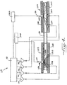
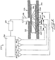
- a device 10 is provided in the preferred embodiment shown in Figures 1 to 3.
- a device 10 is provided in the preferred embodiment shown in Figures 1 to 3.
- the red cells are spherized.
- the present invention may be advantageously applied to circulating blood within an extracorporeal circuit, without detrimental effect on the blood.
- housing 12 Made of opaque plastic, housing 12 includes a channel 14 for receiving a light transmissive, flow cell 22, which has extracorporeal circuit tubing 24 attached to each end.
- device 10 includes means 26,27 for generating light beams, which may be the same or different wavelengths. Conventional drivers 30A,30B for each light source may be suitably used.
- a light source that emits an isobestic wavelength is used.
- a useful isobestic wavelength in the IR range is approximately 815 nm.
- Other useful wavelengths include 940 nm (IR) and 670 nm (red).
- 940 nm is advantageous due to its particular sensitivity to water.
- a beneficial combination is an isobestic IR wavelength and a red wavelength, for instance, 815 nm and 670 nm.
- Lasers are highly advantageous light sources.
- Other light sources include laserdiodes, LEDs and incandescent light sources. Like lasers, laserdiodes beneficially emit virtually a single wavelength. Incandescent light sources directed across narrow band width interference filters, may be used.
- each light source is disposed in a cylindrical opening 16 in a cover 18 of opaque plastic housing 12.
- the cylindrical openings serve to collimate the light beams.
- light sources 26,27 may be disposed remote from the housing. In this case, fiber optic cable carrying specific light, may be used.
- device 10 includes detector means for detecting light emerging from the blood. These detector means are positioned at suitable locations for sensitivity to the intensity and geometry of the emerging light. Conventional photodiodes may be used. Importantly, light detector means 32,33 are disposed at different locations with respect to each light beam. The areas illuminated by light sources 26,27 are represented in Figure 3, and indicate transmitted and scattered light for each beam of light.
- Light detection means 32 is beneficially located so as to predominantly be sensitive to directly emerging light, that is, with light that maintains a generally straight-line path through the blood.
- detector 32 is directly illuminated by light source 26, and may be located in the center of the light beam, that is, in line with optical axis "a".
- the blood path length of directly transmitted light is typically about 3 mm or more.
- Light detection means 33 is located so as to be sensitive to emerging light that has been scattered, and for convenience, may be termed a "side detector".
- detectors 32,33 are spaced apart but located proximate to one another.
- An appropriate spacing depends upon factors including the length of the light path. For example, the spacing will be greater than the light path, and the spacing will be sufficient so that information from one detector differs from information from another detector.
- a spacing of about 1 cm, center to center provides advantageous resolution for a light path of about 3mm; too close a spacing as in the prior art catheter of Moran, should be avoided.
- the detectors are located within an opposite side 20 of the housing from the light sources and situated so as to be adjacent the flow cell. Suitable dimensions for the detectors are about 4 mm x 5 mm.
- the location of the second light source is the location of the second light source.
- neither detector is directly illuminated by light source 27.
- optical axis "b" of a light beam from the second light source is spaced apart from the optical axis of the first light beam, and projects between detectors 32,33.
- detector 33 is not a "through detector” for light source 27.
- light source 27 is offset so that optical axis "b" is closer to one detector than to the other.
- light source 27 is advantageously located relatively closer to detector 33 than to detector 32, and thus, with respect to light source 27, detector 33 may be termed a "near detector” and detector 32 may be termed a "far detector”.
- light source 27 may be located, center to center, a distance of about 0.4 cm from detector 33, and a distance of about 0.6 cm from detector 32, using optical axis "b" as the center.
- two detectors may provide four distinct detection locations.
- detectors 32,33 were equidistant from optical axis "b", there would not be four distinct locations.
- light detector 32 may be located so as to be sensitive to directly emerging light emanating from the 815 nm light source; and the 670 light source may be located so that light detector 32 is a "far detector” and light detector 33 is a "near detector”.
- flow cell 22 is beneficially shaped to generally conform to the geometry of channel 14.
- light transmissive tubing inserted into extracorporeal circuit tubing 24 may be used in place of the flow cell, and the tubing may be conformed to the channel geometry upon the closing of cover 18.
- device 10 further includes signal amplification means.
- signal amplification means Suitably, conventional operational amplifiers may be used.
- a first amplification means 41 operatively communicates with detector 32, and a second amplification means 42 operatively communicates with detector 33.
- a third amplification means 43 operatively communicates with detector 32, and a fourth amplification means 44 operatively communicates with detector 33. Detected signals from optically distinct locations are separately amplified.
- the device advantageously includes conventional analog to digital (A/D) converter means and signal processing means 50.
- A/D converter means includes four channels for separately processing the four incoming signals, for feeding to the signal processing means.
- the signal processing means operatively communicates with, and serves to separately evaluate the signals received from, the individual amplification means.
- a conventional microprocessor may be used as the signal processing means. Switching between a detector and particular amplification means may be suitably provided by conventional switch means for controlling signal feed from the detectors, and may be conveniently controlled by the microprocessor.
- the microprocessor advantageously controls emission by light sources 26,27, via drivers 30A,30B. More particularly, in device 10, the light sources are pulsed sequentially, preferably using stable current supplies. Switching between drivers may be conveniently controlled by the microprocessor, and is beneficially coordinated with detector/amplification means switching. Photodetector signals, proportional to incident light, are processed by the microprocessor, which beneficially functions to use signal information to determine blood parameters of interest.
- each light beam may be split so as to be directed partially toward housing 12 and partially toward a second housing provided with a reference flow cell containing a standard.
- the second housing may be conveniently structured in like manner as housing 12, and will preferably include a pair of light sources and a pair of detectors located in identical manner as light sources 26,27 and detectors 32,33, and will be appropriately connected to the described circuitry. Signals from this reference flow cell may be processed in a similar manner as described in U.S. Patent No. 5,331,958 for detectors 32,33 thereof.
- Use of a second housing permits calibration readings under the control of the microprocessor without removal of flow cell 22 from housing 12.
- an operator removes flow cell 22 from housing 12 and inserts the reference flow cell.
- inaccuracy resulting from variability in or in aging of the detectors will be avoided, and greater reliability should result.
- a calibrating standard for assigning a selected value to emerging light sensed at detector 32 and a selected value to emerging light sensed at detector 33 is beneficial.
- calibration means 60 for scattering a light beam to a suitable reference geometry is advantageously used.
- the reference geometry may differ from that of blood.
- a useful calibrating standard is provided by a light transmissive, flow cell 62 having elements 64 corresponding to grooves in housing 12, filled with a suitable calibrating matrix 66, and sealed at its ends using plugs 68.
- An appropriate particle size for a particular reference geometry depends upon factors including the length of the light path, because particle size and length of light path influence the degree of scatter. Generally speaking, to obtain a given degree of scatter, a relatively longer light path permits the use of relatively smaller particle size, whereas a relatively shorter light path will require the use of relatively larger particle size.
- the matrix particles are three-dimensionally fixed in their respective positions.
- the calibrating matrix may require a light-absorbing additive to prevent saturation of the detectors.
- a light-absorbing additive to prevent saturation of the detectors.
- particles of about 1 mm were used, such an additive may not be necessary; whereas particles of about 5 microns would typically require the additive.
- a suitable dye and/or colorant for use as a light-absorbing additive is stable under the conditions of use, will selectively absorb light, and will be optimized to the light wavelengths to be used. Typically, the absorption will be in the visible and near infrared spectrum.
- Exemplary useful additives include copper phthalocyanine, indocyanine green, naphthol green B, prussian blue, and nigrosin.
- matrix 66 may be provided by a homogeneous mixture of a silicone lubricant and a suitable additive or additives.
- the lubricant will be of sufficient viscosity under the conditions of use, to maintain a homogeneous mixture.
- a silicone lubricant available as Dow Corning Product #111.
- a clear liquid such as the saline solution of Bailey, would not be useful in the present invention, because little scatter would be produced.
- a useful calibrating standard may be prepared by mixing a suitable additive and matrix to provide a homogeneous mixture, charging the flow cell with the mixture, and sealing the filled flow cell.
- a small amount of additive is used in proportion to the matrix, and as indicated, is sufficient to prevent saturation of the detectors.
- the additive is copper phthalocyanine and the matrix is silicone lubricant, about 10 mg of additive may be conveniently mixed with about 4 gm of the matrix.
- a method for determining blood parameters from optical properties of blood by using information contained in scatter is provided.
- at least one light beam is advantageously directed into a patient's circulating blood, and light emerging from the blood is detected and measured using three or more distinct detection locations.
- the detection units may consist of through detector 32, and at an optically distinct location suitable for sensitivity to intensity and geometry of an emerging light beam, side detector 33; however, other elements or procedures useful for providing signals capable of enabling evaluation of the intensity and geometry of an emerging light beam, may be used.
- calibration means 60 is placed into housing 12, the light sources are pulsed directing each light beam into the calibrating means, and a selected value is assigned to the emerging light detected and measured at each distinctly located detector. Thereafter, signal data are accumulated over a selected period of time using device 10, and independently measured data for a blood parameter or parameters of interest are obtained. The signal data and measured data are beneficially obtained substantially simultaneous in time. Based thereon, an appropriate equation including derived constant values, may be determined. By thereafter obtaining signal data at a subsequent point in time using device 10, and using the resultant signal information for solving the equation, the value of the blood parameter or parameters of interest at that subsequent point in time, may be determined independently of other blood parameters. As previously described, detector signals are separately amplified, and amplified signals are separately received by the signal processing means. Calibration may be at the outset and thereafter as appropriate.
- multiple regression analysis is advantageously used to derive the constants A, B, C ... I from the data accumulated over the selected period of time using device 10, and from the measured data for the blood parameter of interest.
- the constants will likely vary depending upon the blood parameter of interest.
- Evaluation is advantageously used to find components of the equation that either contribute insignificantly or do not contribute positively to the determination. Such components may be disregarded in selecting an appropriate equation. Variation in useful components of an equation may be expected depending upon factors including the blood parameter of interest and the wavelength or wavelengths used.
- the foregoing equation beneficially includes data for intensity of emerging light of one wavelength detected at a first distinct detection location, data for intensity of emerging light of the same wavelength detected at a second distinct detection location, data for total intensity, and data for a ratio of the intensities.
- ratio data particularly inform as to the light beam geometry.
- an equation specify ratio data for emerging light beam geometry to be evaluated.
- device 10 may be used on-line to continuously or intermittently monitor blood parameters by measuring light transmission changes across the circuit tubing or a flow cell inserted into the circuit.
- rate of ultrafiltration may be optimized by providing for the maximum rate of fluid removal which will not result in a sustained or excessive increase in hemoglobin, that is, the maximal rate of fluid removal which can be matched safely by fluid mobilization from the tissues into the blood stream.
- Hemoglobin concentration may be a better index of circulating blood volume than hematocrit, because hematocrit can be influenced by the mean corpuscular volume.
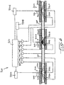
- FIG. 4 a second preferred embodiment of the present invention is shown, in which to avoid the use of pulsed light sources, each light source is followed by separate detectors.
- Corresponding numerals are used in Figure 4 to indicate parts of device 110 corresponding to device 10, and, for sake of brevity, no description is given of corresponding parts except as otherwise now provided.
- device 110 includes flow cells 122A,122B disposed within housings 112A,112B, extracorporeal circuit tubing 124 connecting the flow cells, and means 126,127 for generating light beams and detecting means 132A,133A,132B,133B disposed within the respective housings.
- Driver 130A drives the first light source
- driver 130B drives the second light source.
- the areas illuminated by the light sources are represented in Figure 4, and indicate transmitted and scattered light for each beam of light.
- each flow cell has a single light source and a separate set of detectors.
- the detectors within a set may be spaced apart, center to center, a distance of about 1 cm.
- one detector may be located so as to predominantly be sensitive to directly emerging light, and no other detector is directly illuminated by a light source.
- Optical axis "c" of a light beam from light source 127 projects between detectors 132B,133B.
- light source 127 is offset so that the optical axis is closer to one detector than to the other.
- detector 132A may be located to be predominantly sensitive to directly emerging light emanating from the 815 nm light source; and the 670 nm light source may be located so that detector 132B is a "far detector” and detector 133B is a "near detector”.
- a first amplification means 141 operatively communicates with detector 132A
- a second amplification means 142 operatively communicates with detector 133A
- a third amplification means 143 operatively communicates with detector 132B
- a fourth amplification means 144 operatively communicates with detector 133B.
- the device suitably includes conventional analog to digital (A/D) converter means and signal processing means 150.
- the A/D converter means includes four channels for separately processing the signals.
- the experimental design is as follows: each day over an eight day period, a circuit including flow cells 122A,122B is charged with approximately 250 ml fresh blood. The flow cells are respectively disposed in housings 112A,112B. Subsequently, four 15 ml volumes of plasma are added to the circuit at appropriate intervals. Then, four 400 microliter volumes of 3 M sodium chloride are added to the circuit at appropriate intervals. Then, four 15 ml volumes of ultrafiltrate are removed from the circuit at appropriate intervals. Then, four 15 ml volumes of ultrafiltrate are added to the circuit at appropriate intervals. Oxygen tension is varied by changing the % O 2 in contact with the blood.
- Signal data are obtained using device 110 to monitor the foregoing interventions, and simultaneously measured data for hematocrit and pO 2 are obtained. Hematocrit is measured using a standard microhematocrit technique and an electrode measurement is used for pO 2 . Each day over the eight day period, this experimental protocol is followed. As may be understood, this protocol results in the collection of signal data for hematocrit, while macromolecular (in particular protein) concentration and sodium concentration are changed in the circulating blood.
- the accumulated signal data are correlated with the accumulated measured data for each of hematocrit and pO 2 , and the constants and other pertinent information are derived, as shown in Table 1, for each of hematocrit and pO 2 .
- constants A, B, C ... H are the "X coefficient(s)" in the order shown, and constant I is the "Constant”.
- hematocrit is determined independently of specifically following or measuring protein or sodium concentration.
- the device of Figure 4 of U.S. Patent 5,331,958 will generally produce less accurate results.
- the combination of one light source and two detectors provides comparatively less information as to change in intensity and geometry of the emerging light beam.
- hemoglobin or protein may be determined independently of measuring or specifically following hematocrit or sodium concentration.
- Applications include determination of blood concentration of additional hemoglobin species.
- wavelengths appropriate for optical detection of these species including carboxyhemoglobin and methemoglobin, may be used.
- FIG. 5 a third preferred embodiment of the present invention is shown, in which a single light source is used with four detectors.
- Corresponding numerals are used in Figure 5 to indicate parts of device 210 corresponding to device 10, and, for sake of brevity, no description is given of corresponding parts except as otherwise now provided.
- device 210 includes a flow cell 222 disposed within a housing 212, a light source 226, which is preferably a 815 nm light source, and four detectors 232A,233A,232B,233B. Beneficially, each detector is differently located with respect to the light source to receive different information.
- the area illuminated by the light source is represented in the Figure.
- one detector may be located so as to predominantly be sensitive to directly emerging light emanating from the light source, and no other detector is directly illuminated by the light source.
- Optical axis "e" of a light beam from the light source projects between detectors 233B,232B, and these detectors are located at a different distance with respect to the optical axis. As shown, detector 233B is a "near detector” and detector 232B is a "far detector”.
- detectors 232A,233A are spaced apart, center to center, a distance “d1” of about 1 cm
- detectors 233B,232B are likewise spaced apart, center to center, a distance of about 1 cm.
- Optical axis "e" of the light beam is located a distance d2 of about 0.4 cm from detector 233B (center), and a distance d3 of about 0.6cm from detector 232B (center).
- FIG. 6 a fourth preferred embodiment of the present invention is shown, in which three light sources are used, and each light source is followed by a separate set of detectors.
- Corresponding numerals are used in Figure 6 to indicate parts of device 310 corresponding to device 110, and, for sake of brevity, no description is given of corresponding parts except as otherwise now provided.
- device 310 includes flow cells 322A,322B,322C disposed within housings 312A,312B,312C, extracorporeal circuit tubing 324 connecting the flow cells, means 326,327,328 for generating light beams and detecting means 332A,333A,332B,333B,332C, 333C disposed within the respective housings.
- Driver 330A drives the first light source
- driver 330B drives the second light source
- driver 330C drives the third light source.
- the areas illuminated by the light sources are represented in the Figure.
- each flow cell has a single light source and a separate set of detectors.
- the detectors within a set may be spaced apart, center to center, a distance of about 1 cm.
- at least one detector may be located so as to predominantly be sensitive to directly emerging light.
- two detectors may be so located; otherwise, no other detector is directly illuminated by a light source.
- Optical axis "f" of a light beam from light source 327 projects between detectors 332B,333B. Light source 327 is offset so as to be closer to one detector than the other.
- the detectors are located so as to provide four distinct detection locations.
- Detectors 332C,333C are suitably similarly disposed as detectors 332A,333A.
- detector 332A may be located to be predominantly sensitive to directly emerging light emanating from the 815 nm light source; the 670 light source may be located so that detector 332B is a "far detector” and detector 333B is a "near detector”; and detector 332C may be located to be predominantly sensitive to directly emerging light emanating from the 940 nm light source.
- a first amplification means 341 operatively communicates with detector 332A
- a second amplification means 342 operatively communicates with detector 333A
- a third amplification means 343 operatively communicates with detector 332B
- a fourth amplification means 344 operatively communicates with detector 333B
- a fifth amplification means 345 operatively communicates with detector 332C
- a sixth amplification means 346 operatively communicates with detector 333C.
- the device suitably includes conventional analog to digital (A/D) converter means and signal processing means 350.
- A/D converter means 350 includes six channels for separately processing the signals.
- processing of signal information to determine a blood parameter (BP) of interest may be by the use of the following equation which follows intensity and geometry of an emerging light beam, when wavelengths of 815 nm, 670 nm and 940 nm are used in housings 312A,312B,312C, respectively:
- BP Alog815TH + Blog815SD + C(log815THxlog815SD) + D(log815TH/log815SD) + Elog670NR + Flog670FR + G(log670NRxlog670FR) + H(log670NR/log670FR) + Ilog940TH + Jlog940SD + K(log940THxlog940SD) + L(log940TH/log940SD) + M, where 815TH is the signal from through detector 332A, 815SD is the signal from side detector 333A, 670NR is the signal from near detector 333B, 670FR is the signal from far detector 332B, 9
- M are constants. As before, this equation would be the same for other wavelengths except that the equation may specify the other wavelengths used. Also, total intensity could be evaluated by a sum of logs, rather than, as shown, a product of logs; and the determination may not necessarily always require log calculations, and may even use a combination of logs and ordinary numbers.
- BP A815TH + B815SD + E670NR + F670FR + I940TH + J940SD + M.
- BP B815SD + F670FR + I940TH + M, with a relative weighting based upon degree of importance, being 940TH, 815SD and 670FR in the order given.
- the monitoring devices and method of the present invention may be used on-line with an extracorporeal circuit through which a patient's blood is circulated.
- the inventive concept is equally applicable to analysis of blood in a body part that can be transilluminated.
- the invention may be applied to non-invasive devices (probes).
- the invention may be embodied in clip-like devices for attachment to body parts which can be transilluminated such as fingers, toes and ear lobes.
- net volume exchange with or from the circulating vascular volume (VC) at any time (t)
- VE net volume exchange
- VC circulating vascular volume
- Hbg 0 the initial hemoglobin
- Hbg(t) the concentration of hemoglobin at time (t).
- Monitoring of volume exchanged is of value in the mobilization of edema because if edema is mobilized into the blood stream, fluid must be removed appropriately to prevent dangerous increases in VC and excessive anemia.
- fluid removal is undertaken in conjunction with acute dialysis, in which case a monitoring device in accordance with the present invention, may be attached to the dialysis circuit. If dialysis is not undertaken, a non-invasive device in accordance with the present invention, may be used.
- Applications of the present invention include monitoring of fluid balance with appropriate feedback.
- a monitoring device in accordance with the present invention is placed on an intermittent or continuous dialysis system, proximal to the filtering device, a patient's hemoglobin and the volume exchanged from the patient's blood volume may be continuously monitored and displayed.
- This information may support a feed-back electronic system to regulate the rate of ultrafiltration and to maintain an adequate and safe circulating blood volume while fluid exchange is induced.
Landscapes
- Physics & Mathematics (AREA)
- Health & Medical Sciences (AREA)
- Life Sciences & Earth Sciences (AREA)
- Chemical & Material Sciences (AREA)
- Analytical Chemistry (AREA)
- Biochemistry (AREA)
- General Health & Medical Sciences (AREA)
- General Physics & Mathematics (AREA)
- Immunology (AREA)
- Pathology (AREA)
- External Artificial Organs (AREA)
- Investigating Or Analysing Materials By Optical Means (AREA)
Applications Claiming Priority (2)
| Application Number | Priority Date | Filing Date | Title |
|---|---|---|---|
| US365033 | 1994-12-28 | ||
| US08/365,033 US5601080A (en) | 1994-12-28 | 1994-12-28 | Spectrophotometric blood analysis |
Publications (2)
| Publication Number | Publication Date |
|---|---|
| EP0720013A2 true EP0720013A2 (de) | 1996-07-03 |
| EP0720013A3 EP0720013A3 (de) | 1997-09-10 |
Family
ID=23437204
Family Applications (1)
| Application Number | Title | Priority Date | Filing Date |
|---|---|---|---|
| EP95120573A Withdrawn EP0720013A3 (de) | 1994-12-28 | 1995-12-27 | Spektrophotometrische Blutanalyse |
Country Status (2)
| Country | Link |
|---|---|
| US (1) | US5601080A (de) |
| EP (1) | EP0720013A3 (de) |
Cited By (13)
| Publication number | Priority date | Publication date | Assignee | Title |
|---|---|---|---|---|
| EP0800074A1 (de) * | 1996-04-02 | 1997-10-08 | AVL Medical Instruments AG | Vorrichtung und Verfahren zur Bestimmung der Konzentration von Hämoglobinderivaten in einer unverdünnten, unhämolysierten Vollblutprobe |
| RU2149383C1 (ru) * | 1998-12-04 | 2000-05-20 | Бородюк Нелли Рафкатовна | Устройство для исследования взвеси эритроцитов |
| WO2000033053A1 (en) * | 1998-11-30 | 2000-06-08 | Gambro Ab | Method and device for measuring blood parameters |
| US6388752B1 (en) | 1999-05-20 | 2002-05-14 | F. Hoffmann-La Roche Ag | Optical measurement system for determination of transmitted and scattered radiation |
| EP1125126A4 (de) * | 1998-11-06 | 2004-12-29 | Medtronic Avecor Cardiovascula | Vorrichtung und verfahren zum bestimmen von blutwerten |
| EP1748292A1 (de) * | 2002-12-20 | 2007-01-31 | Optoq AB | Vorrichtung für Messungen im Blut |
| US7648475B2 (en) | 2001-12-28 | 2010-01-19 | Gambro Lundia Ab | Non-invasive device for measuring blood temperature in a circuit for the extracorporeal circulation of blood, and equipment provided with this device |
| EP2023803A4 (de) * | 2006-05-17 | 2010-09-01 | Alfred E Mann Inst Biomed Eng | Messung des herzzeitvolumens und blutvolumens mittels nicht-invasiven nachweises der indikatorverdünnung für hämodialyse |
| EP2272428A1 (de) * | 2009-07-09 | 2011-01-12 | University of Tsukuba | Blutstrommessvorrichtung und Hirnaktivitätsmessvorrichtung damit |
| CN101953683A (zh) * | 2009-07-14 | 2011-01-26 | 国立大学法人筑波大学 | 血流测量装置及使用该血流测量装置的脑活动测量装置 |
| US8337444B2 (en) | 2001-05-22 | 2012-12-25 | Alfred E. Mann Institute For Biomedical Engineering At The University Of Southern California | Measurement of cardiac output and blood volume by non-invasive detection of indicator dilution for hemodialysis |
| EP2666492A1 (de) * | 2012-05-23 | 2013-11-27 | B. Braun Avitum AG | Medizinisches Gerät zur extrakorporalen Blutbehandlung mit mehreren Sensoreinheiten |
| US8945018B2 (en) | 2008-02-14 | 2015-02-03 | University Of Tsukuba | Blood flow measuring apparatus and brain activity measuring apparatus using the same |
Families Citing this family (86)
| Publication number | Priority date | Publication date | Assignee | Title |
|---|---|---|---|---|
| US6212424B1 (en) | 1998-10-29 | 2001-04-03 | Rio Grande Medical Technologies, Inc. | Apparatus and method for determination of the adequacy of dialysis by non-invasive near-infrared spectroscopy |
| US6061590A (en) * | 1997-06-03 | 2000-05-09 | Transonic Systems, Inc. | Method and apparatus for predicting intradialytic morbid events through the monitoring of a central blood volume |
| CA2210791A1 (en) * | 1997-07-18 | 1999-01-18 | The University Of Manitoba | Diagnosis of edema |
| GB2328279B (en) * | 1997-08-12 | 2001-10-10 | Abbott Lab | Optical glucose detector |
| US6718190B2 (en) * | 1997-10-14 | 2004-04-06 | Transonic Systems, Inc. | Sensor calibration and blood volume determination |
| US6041246A (en) | 1997-10-14 | 2000-03-21 | Transonic Systems, Inc. | Single light sensor optical probe for monitoring blood parameters and cardiovascular measurements |
| DE19807939C1 (de) * | 1998-02-25 | 1999-09-30 | Siemens Ag | Verfahren und Vorrichtung zur nichtinvasiven optischen Bestimmung der Blutglukosekonzentration |
| US6083158A (en) * | 1998-09-01 | 2000-07-04 | The United States Of America As Represented By The Administrator Of The National Aeronautics And Space Administration | Real-time visualization of tissue ischemia |
| US6877713B1 (en) | 1999-07-20 | 2005-04-12 | Deka Products Limited Partnership | Tube occluder and method for occluding collapsible tubes |
| WO2001053806A1 (en) * | 2000-01-18 | 2001-07-26 | Radiometer Medical A/S | Apparatus, sample cuvette and method for optical measurements |
| US6577884B1 (en) | 2000-06-19 | 2003-06-10 | The General Hospital Corporation | Detection of stroke events using diffuse optical tomagraphy |
| US7283223B2 (en) * | 2002-08-21 | 2007-10-16 | Honeywell International Inc. | Cytometer having telecentric optics |
| US7242474B2 (en) * | 2004-07-27 | 2007-07-10 | Cox James A | Cytometer having fluid core stream position control |
| US7262838B2 (en) * | 2001-06-29 | 2007-08-28 | Honeywell International Inc. | Optical detection system for flow cytometry |
| US6549275B1 (en) * | 2000-08-02 | 2003-04-15 | Honeywell International Inc. | Optical detection system for flow cytometry |
| US7420659B1 (en) * | 2000-06-02 | 2008-09-02 | Honeywell Interantional Inc. | Flow control system of a cartridge |
| US7641856B2 (en) * | 2004-05-14 | 2010-01-05 | Honeywell International Inc. | Portable sample analyzer with removable cartridge |
| US7130046B2 (en) * | 2004-09-27 | 2006-10-31 | Honeywell International Inc. | Data frame selection for cytometer analysis |
| US20060263888A1 (en) * | 2000-06-02 | 2006-11-23 | Honeywell International Inc. | Differential white blood count on a disposable card |
| US8071051B2 (en) | 2004-05-14 | 2011-12-06 | Honeywell International Inc. | Portable sample analyzer cartridge |
| US8329118B2 (en) * | 2004-09-02 | 2012-12-11 | Honeywell International Inc. | Method and apparatus for determining one or more operating parameters for a microfluidic circuit |
| US7471394B2 (en) * | 2000-08-02 | 2008-12-30 | Honeywell International Inc. | Optical detection system with polarizing beamsplitter |
| US7016022B2 (en) * | 2000-08-02 | 2006-03-21 | Honeywell International Inc. | Dual use detectors for flow cytometry |
| US7630063B2 (en) * | 2000-08-02 | 2009-12-08 | Honeywell International Inc. | Miniaturized cytometer for detecting multiple species in a sample |
| US7061595B2 (en) * | 2000-08-02 | 2006-06-13 | Honeywell International Inc. | Miniaturized flow controller with closed loop regulation |
| US7000330B2 (en) * | 2002-08-21 | 2006-02-21 | Honeywell International Inc. | Method and apparatus for receiving a removable media member |
| US7277166B2 (en) * | 2000-08-02 | 2007-10-02 | Honeywell International Inc. | Cytometer analysis cartridge optical configuration |
| ITTO20010189A1 (it) * | 2001-03-02 | 2002-09-02 | Gambro Dasco Spa | Metodo per misurare la concentrazione di emoglobina nel sangue in un circuito di una macchina di dialisi, dispositivo di misura e circuito p |
| SE0104443D0 (sv) * | 2001-12-28 | 2001-12-28 | Hemocue Ab | Analysis method and cuvette therefor |
| JP4129866B2 (ja) * | 2002-07-18 | 2008-08-06 | 日機装株式会社 | 血液処理装置 |
| US7612871B2 (en) * | 2004-09-01 | 2009-11-03 | Honeywell International Inc | Frequency-multiplexed detection of multiple wavelength light for flow cytometry |
| US7630075B2 (en) * | 2004-09-27 | 2009-12-08 | Honeywell International Inc. | Circular polarization illumination based analyzer system |
| EP1875200A1 (de) | 2005-04-29 | 2008-01-09 | Honeywell International Inc. | Zytometerbasiertes verfahren zur zellzählung und grössenmessung |
| CN101253401B (zh) * | 2005-07-01 | 2013-01-02 | 霍尼韦尔国际公司 | 带三维流体动力学集中的模制标本盒 |
| JP4995197B2 (ja) * | 2005-07-01 | 2012-08-08 | ハネウェル・インターナショナル・インコーポレーテッド | 3d流体力学的集束を有する成形カートリッジ |
| US8361410B2 (en) * | 2005-07-01 | 2013-01-29 | Honeywell International Inc. | Flow metered analyzer |
| US7843563B2 (en) * | 2005-08-16 | 2010-11-30 | Honeywell International Inc. | Light scattering and imaging optical system |
| WO2007075922A2 (en) * | 2005-12-22 | 2007-07-05 | Honeywell International Inc. | Portable sample analyzer cartridge |
| JP5175213B2 (ja) * | 2005-12-22 | 2013-04-03 | ハネウェル・インターナショナル・インコーポレーテッド | 携帯用サンプル分析システム |
| WO2007075920A2 (en) * | 2005-12-22 | 2007-07-05 | Honeywell International Inc. | Hematological analyzer system with removable cartridge |
| JP5431732B2 (ja) * | 2005-12-29 | 2014-03-05 | ハネウェル・インターナショナル・インコーポレーテッド | マイクロ流体フォーマットにおけるアッセイ実装 |
| DE102006029899B4 (de) | 2006-06-29 | 2009-06-04 | Fresenius Medical Care Deutschland Gmbh | Spektroskopischer Detektor und Verfahren zur Bestimmung von Blut und biologischen Markersubstanzen in Flüssigkeiten |
| KR100812249B1 (ko) | 2007-05-07 | 2008-03-10 | 제이에스엠헬스케어 주식회사 | 혈액튜브를 통한 헤모글로빈 값 측정 및 표시장치 |
| WO2008136548A1 (en) * | 2007-05-07 | 2008-11-13 | Jsm Healthcare Inc | Device of measuring and monitoring a hemoglobin value through blood tube |
| JP2009083382A (ja) * | 2007-10-01 | 2009-04-23 | Brother Ind Ltd | 画像形成装置および画像処理プログラム |
| US20090156916A1 (en) * | 2007-12-18 | 2009-06-18 | Huisun Wang | Catheter systems with blood measurement device and methods |
| MX340210B (es) | 2008-01-23 | 2016-06-29 | Deka Products Ltd Partnership * | Componentes desechables para sistemas y métodos de autoconexión de una linea de fluido. |
| US9078971B2 (en) | 2008-01-23 | 2015-07-14 | Deka Products Limited Partnership | Medical treatment system and methods using a plurality of fluid lines |
| US20090310123A1 (en) * | 2008-06-16 | 2009-12-17 | Robert John Thomson | Blood concentrate detector |
| US20100004518A1 (en) | 2008-07-03 | 2010-01-07 | Masimo Laboratories, Inc. | Heat sink for noninvasive medical sensor |
| US8630691B2 (en) | 2008-08-04 | 2014-01-14 | Cercacor Laboratories, Inc. | Multi-stream sensor front ends for noninvasive measurement of blood constituents |
| US20100034704A1 (en) * | 2008-08-06 | 2010-02-11 | Honeywell International Inc. | Microfluidic cartridge channel with reduced bubble formation |
| US8037354B2 (en) | 2008-09-18 | 2011-10-11 | Honeywell International Inc. | Apparatus and method for operating a computing platform without a battery pack |
| DE102009005402B4 (de) * | 2009-01-19 | 2011-11-24 | Fresenius Medical Care Deutschland Gmbh | Verfahren zum Bestimmen der Konzentration von Blutbestandteilen in einer mit Blut gefüllten Schlauchleitung |
| WO2011053810A2 (en) | 2009-10-30 | 2011-05-05 | Deka Products Limited Partnership | Apparatus and method for detecting disconnection of an intravascular access device |
| US9002655B2 (en) | 2010-05-03 | 2015-04-07 | Gambro Lundia Ab | Medical apparatus for extracorporeal blood treatment and method for determining a blood parameter value in a medical apparatus thereof |
| EP3279703B2 (de) | 2010-07-07 | 2022-06-29 | DEKA Products Limited Partnership | Medizinisches behandlungssystem und verfahren anhand der verwendung mehrerer flüssigkeitsleitungen |
| MX344664B (es) | 2011-05-24 | 2017-01-04 | Deka Products Lp | Sistemas y metodos de tratamiento de la sangre. |
| US9999717B2 (en) | 2011-05-24 | 2018-06-19 | Deka Products Limited Partnership | Systems and methods for detecting vascular access disconnection |
| EP3498316B1 (de) | 2011-11-04 | 2020-07-22 | DEKA Products Limited Partnership | System und verfahren zur medizinischen behandlung unter verwendung einer vielzahl von flüssigkeitsleitungen |
| US8663583B2 (en) | 2011-12-27 | 2014-03-04 | Honeywell International Inc. | Disposable cartridge for fluid analysis |
| US8741234B2 (en) | 2011-12-27 | 2014-06-03 | Honeywell International Inc. | Disposable cartridge for fluid analysis |
| US8741233B2 (en) | 2011-12-27 | 2014-06-03 | Honeywell International Inc. | Disposable cartridge for fluid analysis |
| US8741235B2 (en) | 2011-12-27 | 2014-06-03 | Honeywell International Inc. | Two step sample loading of a fluid analysis cartridge |
| JP5901012B2 (ja) * | 2012-02-13 | 2016-04-06 | 国立大学法人 東京医科歯科大学 | 血液情報の測定方法及び装置 |
| WO2014049831A1 (ja) * | 2012-09-28 | 2014-04-03 | ニプロ株式会社 | 流体濃度の測定方法および測定装置 |
| US9308306B2 (en) * | 2014-02-24 | 2016-04-12 | Fresenius Medical Care Holdings, Inc. | Self calibrating blood chamber |
| DE102014011695A1 (de) * | 2014-08-07 | 2016-02-11 | Fresenius Medical Care Deutschland Gmbh | Blutbehandlungsvorrichtung mit einer Funktionseinheit zur Durchführung der Blutbehandlung und Verfahren zur Überprüfung der Funktionsfähigkeit und/oder des Betriebszustandes der Funktionseinheit |
| CN107636446B (zh) * | 2015-02-18 | 2021-11-23 | H·施特普 | 用于血液荧光团确定的组织荧光测量的装置和方法 |
| EP3260840B1 (de) * | 2016-06-22 | 2023-06-07 | Uponor Oyj | Anordnung zur inline-holografiemikroskopie |
| JP2019213570A (ja) * | 2016-10-19 | 2019-12-19 | アルプスアルパイン株式会社 | 計測装置および血液循環装置 |
| DE102017001484A1 (de) | 2017-02-16 | 2018-08-16 | Fresenius Medical Care Deutschland Gmbh | Verfahren und Anordnung zum Kalibrieren von Vorrichtungen zur Erkennung von Blut oder Blutbestandteilen in einer Flüssigkeit |
| EP3476483B1 (de) * | 2017-10-30 | 2022-03-02 | ARKRAY, Inc. | Analysevorrichtung |
| JP6986266B2 (ja) * | 2017-11-14 | 2021-12-22 | ジーニアルライト株式会社 | 体液分析装置 |
| BR112020011772A2 (pt) * | 2017-12-15 | 2020-11-17 | Gastroklenz Inc. | sistema de monitoramento do sensor para tratamen-tos com base em cateter permanentes |
| DE102019103028A1 (de) * | 2019-02-07 | 2020-08-13 | Fresenius Medical Care Deutschland Gmbh | Simulationsmodell zur Simulation einer Schlauchleitung für einen Blutleckdetektor sowie Verfahren zum Testen eines Blutleckdetektors |
| EP3990049B1 (de) | 2019-06-26 | 2026-04-01 | Gastroklenz Inc. | Systeme, vorrichtungen und verfahren zur fluidüberwachung |
| US11701035B2 (en) | 2019-10-28 | 2023-07-18 | Bruce M. Landy | Noninvasive blood glucose detector and method using IR |
| DE102019132218B4 (de) * | 2019-11-27 | 2023-06-15 | MAX-PLANCK-Gesellschaft zur Förderung der Wissenschaften e.V. | Durchflussmesszelle |
| FR3105728A1 (fr) * | 2019-12-30 | 2021-07-02 | Neurallys | Dispositif de mesure de turbidité de liquide cérébro-spinal et procédé associé |
| FR3112391B1 (fr) * | 2020-07-08 | 2024-11-29 | I Sep | Appareil de détermination du taux d’hémoglobine ou d’hématocrite d’un liquide en circulation |
| US20230347036A1 (en) * | 2020-07-08 | 2023-11-02 | I--Sep | Device For Determining The Level Of Haemoglobin Or Haematocrit Of A Circulating Liquid |
| US20220248985A1 (en) * | 2021-02-11 | 2022-08-11 | SciLogica Corp. | Analyte Sensor Component |
| EP4512330A1 (de) * | 2021-02-11 | 2025-02-26 | SciLogica Corp. | Analytsensorkomponente |
| JP7654276B2 (ja) * | 2023-03-31 | 2025-04-01 | ジーニアルライト株式会社 | 血液分析装置、血液分析方法、及び、血液分析装置用プログラム |
| WO2025257940A1 (ja) * | 2024-06-11 | 2025-12-18 | ジーニアルライト株式会社 | 血液分析装置、血液分析方法、及び、血液分析装置用プログラム |
Citations (2)
| Publication number | Priority date | Publication date | Assignee | Title |
|---|---|---|---|---|
| US3638640A (en) * | 1967-11-01 | 1972-02-01 | Robert F Shaw | Oximeter and method for in vivo determination of oxygen saturation in blood using three or more different wavelengths |
| EP0285307A1 (de) | 1987-03-23 | 1988-10-05 | Ohmeda Inc. | System zur Messung des Korpuskelgehaltes einer Flüssigkeit, zum Beispiel Blut |
Family Cites Families (19)
| Publication number | Priority date | Publication date | Assignee | Title |
|---|---|---|---|---|
| US3705771A (en) * | 1970-01-14 | 1972-12-12 | Bio Physics Systems Inc | Photoanalysis apparatus |
| FR2195907A5 (de) * | 1972-08-10 | 1974-03-08 | Meric Jean Paul | |
| US4243883A (en) * | 1979-01-19 | 1981-01-06 | Midwest Cardiovascular Institute Foundation | Blood hematocrit monitoring system |
| US4515165A (en) * | 1980-02-04 | 1985-05-07 | Energy Conversion Devices, Inc. | Apparatus and method for detecting tumors |
| GB2097529B (en) * | 1981-04-28 | 1984-09-19 | Itt Ind Ltd | Detecting oil in water |
| JPS5829450A (ja) * | 1981-08-18 | 1983-02-21 | 株式会社豊田中央研究所 | ヘマトクリツト測定装置 |
| US4735504A (en) * | 1983-10-31 | 1988-04-05 | Technicon Instruments Corporation | Method and apparatus for determining the volume & index of refraction of particles |
| US4745279A (en) * | 1986-01-02 | 1988-05-17 | American Hospital Supply Corporation | Hematocrit measuring apparatus |
| US5190040A (en) * | 1986-12-26 | 1993-03-02 | Nihon Kohden Corporation | Apparatus for measuring the change in the concentration of a pigment in blood |
| US5149503A (en) * | 1987-07-24 | 1992-09-22 | Terumo Kabushiki Kaisha | Apparatus for measuring hemoglobin concentration and oxygen saturation thereof |
| US4819752A (en) * | 1987-10-02 | 1989-04-11 | Datascope Corp. | Blood constituent measuring device and method |
| GB2228314B (en) * | 1989-02-16 | 1992-11-18 | Hamamatsu Photonics Kk | Examination apparatus |
| US6262798B1 (en) * | 1992-09-29 | 2001-07-17 | Board Of Regents, The University Of Texas System | Method and apparatus for direct spectrophotometric measurements in unaltered whole blood |
| US5048524A (en) * | 1989-03-03 | 1991-09-17 | Camino Laboratories, Inc. | Blood parameter measurement |
| CA2034285A1 (en) * | 1990-02-09 | 1991-08-10 | Masao Yafuso | Method and system for monitoring of blood constituents in vivo |
| USH1114H (en) * | 1990-04-30 | 1992-12-01 | Medtronic, Inc. | Fiber-optic oxygen saturation/hematocrit sensor |
| US5066859A (en) * | 1990-05-18 | 1991-11-19 | Karkar Maurice N | Hematocrit and oxygen saturation blood analyzer |
| US5331958A (en) * | 1992-03-31 | 1994-07-26 | University Of Manitoba | Spectrophotometric blood analysis |
| JP3577335B2 (ja) * | 1993-06-02 | 2004-10-13 | 浜松ホトニクス株式会社 | 散乱吸収体計測方法及び装置 |
-
1994
- 1994-12-28 US US08/365,033 patent/US5601080A/en not_active Expired - Fee Related
-
1995
- 1995-12-27 EP EP95120573A patent/EP0720013A3/de not_active Withdrawn
Patent Citations (2)
| Publication number | Priority date | Publication date | Assignee | Title |
|---|---|---|---|---|
| US3638640A (en) * | 1967-11-01 | 1972-02-01 | Robert F Shaw | Oximeter and method for in vivo determination of oxygen saturation in blood using three or more different wavelengths |
| EP0285307A1 (de) | 1987-03-23 | 1988-10-05 | Ohmeda Inc. | System zur Messung des Korpuskelgehaltes einer Flüssigkeit, zum Beispiel Blut |
Non-Patent Citations (1)
| Title |
|---|
| J. Appl. Physiol. 62(1), 364-372 (1987); cited in the application * |
Cited By (18)
| Publication number | Priority date | Publication date | Assignee | Title |
|---|---|---|---|---|
| EP0800074A1 (de) * | 1996-04-02 | 1997-10-08 | AVL Medical Instruments AG | Vorrichtung und Verfahren zur Bestimmung der Konzentration von Hämoglobinderivaten in einer unverdünnten, unhämolysierten Vollblutprobe |
| EP1125126A4 (de) * | 1998-11-06 | 2004-12-29 | Medtronic Avecor Cardiovascula | Vorrichtung und verfahren zum bestimmen von blutwerten |
| WO2000033053A1 (en) * | 1998-11-30 | 2000-06-08 | Gambro Ab | Method and device for measuring blood parameters |
| US6510330B1 (en) | 1998-11-30 | 2003-01-21 | Gambro Ab | Method and device for measuring blood parameters |
| RU2149383C1 (ru) * | 1998-12-04 | 2000-05-20 | Бородюк Нелли Рафкатовна | Устройство для исследования взвеси эритроцитов |
| US6388752B1 (en) | 1999-05-20 | 2002-05-14 | F. Hoffmann-La Roche Ag | Optical measurement system for determination of transmitted and scattered radiation |
| US8337444B2 (en) | 2001-05-22 | 2012-12-25 | Alfred E. Mann Institute For Biomedical Engineering At The University Of Southern California | Measurement of cardiac output and blood volume by non-invasive detection of indicator dilution for hemodialysis |
| US7648475B2 (en) | 2001-12-28 | 2010-01-19 | Gambro Lundia Ab | Non-invasive device for measuring blood temperature in a circuit for the extracorporeal circulation of blood, and equipment provided with this device |
| EP1748292A1 (de) * | 2002-12-20 | 2007-01-31 | Optoq AB | Vorrichtung für Messungen im Blut |
| EP2023803A4 (de) * | 2006-05-17 | 2010-09-01 | Alfred E Mann Inst Biomed Eng | Messung des herzzeitvolumens und blutvolumens mittels nicht-invasiven nachweises der indikatorverdünnung für hämodialyse |
| US8945018B2 (en) | 2008-02-14 | 2015-02-03 | University Of Tsukuba | Blood flow measuring apparatus and brain activity measuring apparatus using the same |
| EP2272428A1 (de) * | 2009-07-09 | 2011-01-12 | University of Tsukuba | Blutstrommessvorrichtung und Hirnaktivitätsmessvorrichtung damit |
| CN101953683A (zh) * | 2009-07-14 | 2011-01-26 | 国立大学法人筑波大学 | 血流测量装置及使用该血流测量装置的脑活动测量装置 |
| CN101953683B (zh) * | 2009-07-14 | 2014-12-10 | 国立大学法人筑波大学 | 血流测量装置及使用该血流测量装置的脑活动测量装置 |
| CN104207767A (zh) * | 2009-07-14 | 2014-12-17 | 国立大学法人筑波大学 | 血流测量装置及使用该血流测量装置的脑活动测量装置 |
| EP2666492A1 (de) * | 2012-05-23 | 2013-11-27 | B. Braun Avitum AG | Medizinisches Gerät zur extrakorporalen Blutbehandlung mit mehreren Sensoreinheiten |
| EP2666492B1 (de) | 2012-05-23 | 2015-10-14 | B. Braun Avitum AG | Medizinisches Gerät zur extrakorporalen Blutbehandlung mit mehreren Sensoreinheiten |
| US10130749B2 (en) | 2012-05-23 | 2018-11-20 | B. Braun Avitum Ag | Medical device for extracorporeal blood treatment comprising plural sensor units |
Also Published As
| Publication number | Publication date |
|---|---|
| EP0720013A3 (de) | 1997-09-10 |
| US5601080A (en) | 1997-02-11 |
Similar Documents
| Publication | Publication Date | Title |
|---|---|---|
| US5601080A (en) | Spectrophotometric blood analysis | |
| US6144444A (en) | Apparatus and method to determine blood parameters | |
| EP0575712B1 (de) | Spektrophotometrische Blutanalyse | |
| EP0210417B1 (de) | Verfahren und Gerät zur Bestimmung von Blutbestandteilen | |
| EP1147399B1 (de) | Verfahren und vorrichtung zum messen von blutparametern | |
| US6064474A (en) | Optical measurement of blood hematocrit incorporating a self-calibration algorithm | |
| US6103197A (en) | Method and apparatus for optically determining total hemoglobin concentration | |
| CA2221446C (en) | Optical sensor including information element | |
| EP0850013B1 (de) | Verfahren zum bestimmen der fraktionellen sauerstoffsaturation | |
| EP0619981B1 (de) | Sensor zur Überwachung der arteriellen Blutströmung | |
| US5137023A (en) | Method and apparatus for monitoring blood analytes noninvasively by pulsatile photoplethysmography | |
| US5183042A (en) | Electromagnetic method and apparatus to measure constituents of human or animal tissue | |
| US4836206A (en) | Method and device for determining viability of intact teeth | |
| IL94822A (en) | Method and device for determining the properties of a liquid containing biological analyte | |
| Reynolds et al. | The effect of dyshemoglobins on pulse oximetry: Part I, Theoretical approach and Part II, Experimental results using an in vitro test system | |
| De Kock et al. | The effect of varying LED intensity on pulse oximeter accuracy | |
| EP0484547A1 (de) | Messkatheter und messverfahren zur bestimmung der sauerstoffsältigung oder der strömungsgeschwindigkeit von blut | |
| JP2001198111A (ja) | プローブおよび生体組織中吸光物質濃度測定装置 | |
| US5820556A (en) | Method and apparatus for primarily ambulatory gastrointestinal registration | |
| Domanski et al. | Fiber-optic absorptive oximeter | |
| WO1990001691A1 (en) | Particle assay | |
| DK155764B (da) | Fremgangsmaade og apparat til bestemmelse af blodkomponenter | |
| HK1009848B (en) | Oximeter comprising a light source and an information element |
Legal Events
| Date | Code | Title | Description |
|---|---|---|---|
| PUAI | Public reference made under article 153(3) epc to a published international application that has entered the european phase |
Free format text: ORIGINAL CODE: 0009012 |
|
| AK | Designated contracting states |
Kind code of ref document: A2 Designated state(s): DE ES FR GB IT NL SE |
|
| PUAL | Search report despatched |
Free format text: ORIGINAL CODE: 0009013 |
|
| AK | Designated contracting states |
Kind code of ref document: A3 Designated state(s): DE ES FR GB IT NL SE |
|
| 17P | Request for examination filed |
Effective date: 19971219 |
|
| 17Q | First examination report despatched |
Effective date: 20030506 |
|
| STAA | Information on the status of an ep patent application or granted ep patent |
Free format text: STATUS: THE APPLICATION IS DEEMED TO BE WITHDRAWN |
|
| 18D | Application deemed to be withdrawn |
Effective date: 20050701 |