EP0720070A2 - Elément de transport de développateur, ensemble de développement, appareil de formation d'images et unité de traitement - Google Patents
Elément de transport de développateur, ensemble de développement, appareil de formation d'images et unité de traitement Download PDFInfo
- Publication number
- EP0720070A2 EP0720070A2 EP95309446A EP95309446A EP0720070A2 EP 0720070 A2 EP0720070 A2 EP 0720070A2 EP 95309446 A EP95309446 A EP 95309446A EP 95309446 A EP95309446 A EP 95309446A EP 0720070 A2 EP0720070 A2 EP 0720070A2
- Authority
- EP
- European Patent Office
- Prior art keywords
- developer
- conductive
- carrying member
- developer carrying
- coat layer
- Prior art date
- Legal status (The legal status is an assumption and is not a legal conclusion. Google has not performed a legal analysis and makes no representation as to the accuracy of the status listed.)
- Granted
Links
- 238000000034 method Methods 0.000 title claims description 72
- 239000002245 particle Substances 0.000 claims abstract description 177
- 239000012798 spherical particle Substances 0.000 claims abstract description 123
- 229920005989 resin Polymers 0.000 claims abstract description 71
- 239000011347 resin Substances 0.000 claims abstract description 71
- 239000011230 binding agent Substances 0.000 claims abstract description 27
- 239000000758 substrate Substances 0.000 claims abstract description 20
- 230000005291 magnetic effect Effects 0.000 claims description 56
- OKTJSMMVPCPJKN-UHFFFAOYSA-N Carbon Chemical compound [C] OKTJSMMVPCPJKN-UHFFFAOYSA-N 0.000 claims description 38
- 239000000463 material Substances 0.000 claims description 33
- 239000010419 fine particle Substances 0.000 claims description 32
- 229910052799 carbon Inorganic materials 0.000 claims description 18
- 229910052751 metal Inorganic materials 0.000 claims description 17
- 239000002184 metal Substances 0.000 claims description 17
- 239000010439 graphite Substances 0.000 claims description 14
- 229910002804 graphite Inorganic materials 0.000 claims description 14
- 230000001050 lubricating effect Effects 0.000 claims description 14
- 238000012546 transfer Methods 0.000 claims description 12
- 238000004140 cleaning Methods 0.000 claims description 10
- 229910044991 metal oxide Inorganic materials 0.000 claims description 4
- 150000004706 metal oxides Chemical class 0.000 claims description 4
- 239000006229 carbon black Substances 0.000 claims description 3
- 229910052582 BN Inorganic materials 0.000 claims description 2
- PZNSFCLAULLKQX-UHFFFAOYSA-N Boron nitride Chemical compound N#B PZNSFCLAULLKQX-UHFFFAOYSA-N 0.000 claims description 2
- OYPRJOBELJOOCE-UHFFFAOYSA-N Calcium Chemical compound [Ca] OYPRJOBELJOOCE-UHFFFAOYSA-N 0.000 claims description 2
- 229910052791 calcium Inorganic materials 0.000 claims description 2
- 239000011575 calcium Substances 0.000 claims description 2
- 235000014113 dietary fatty acids Nutrition 0.000 claims description 2
- 239000000194 fatty acid Substances 0.000 claims description 2
- 229930195729 fatty acid Natural products 0.000 claims description 2
- 150000004665 fatty acids Chemical class 0.000 claims description 2
- 239000011256 inorganic filler Substances 0.000 claims description 2
- 229910003475 inorganic filler Inorganic materials 0.000 claims description 2
- QLOAVXSYZAJECW-UHFFFAOYSA-N methane;molecular fluorine Chemical compound C.FF QLOAVXSYZAJECW-UHFFFAOYSA-N 0.000 claims description 2
- 239000010445 mica Substances 0.000 claims description 2
- 229910052618 mica group Inorganic materials 0.000 claims description 2
- CWQXQMHSOZUFJS-UHFFFAOYSA-N molybdenum disulfide Chemical compound S=[Mo]=S CWQXQMHSOZUFJS-UHFFFAOYSA-N 0.000 claims description 2
- 229910052982 molybdenum disulfide Inorganic materials 0.000 claims description 2
- 150000003839 salts Chemical class 0.000 claims description 2
- MFPKLLKQAHJKQH-UHFFFAOYSA-N silver niobium(5+) selenium(2-) Chemical compound [Se--].[Se--].[Se--].[Nb+5].[Ag+] MFPKLLKQAHJKQH-UHFFFAOYSA-N 0.000 claims description 2
- 239000000454 talc Substances 0.000 claims description 2
- 229910052623 talc Inorganic materials 0.000 claims description 2
- 230000000704 physical effect Effects 0.000 description 43
- 238000011156 evaluation Methods 0.000 description 31
- 239000011248 coating agent Substances 0.000 description 29
- 238000000576 coating method Methods 0.000 description 29
- 238000001035 drying Methods 0.000 description 27
- 238000012360 testing method Methods 0.000 description 26
- 229920001577 copolymer Polymers 0.000 description 23
- 238000011161 development Methods 0.000 description 20
- PPBRXRYQALVLMV-UHFFFAOYSA-N Styrene Chemical compound C=CC1=CC=CC=C1 PPBRXRYQALVLMV-UHFFFAOYSA-N 0.000 description 19
- MCMNRKCIXSYSNV-UHFFFAOYSA-N Zirconium dioxide Chemical compound O=[Zr]=O MCMNRKCIXSYSNV-UHFFFAOYSA-N 0.000 description 16
- 238000005259 measurement Methods 0.000 description 14
- 239000005011 phenolic resin Substances 0.000 description 14
- 239000000843 powder Substances 0.000 description 14
- 238000011109 contamination Methods 0.000 description 13
- KFZMGEQAYNKOFK-UHFFFAOYSA-N Isopropanol Chemical compound CC(C)O KFZMGEQAYNKOFK-UHFFFAOYSA-N 0.000 description 12
- 239000011324 bead Substances 0.000 description 12
- 230000000052 comparative effect Effects 0.000 description 12
- MYRTYDVEIRVNKP-UHFFFAOYSA-N 1,2-Divinylbenzene Chemical compound C=CC1=CC=CC=C1C=C MYRTYDVEIRVNKP-UHFFFAOYSA-N 0.000 description 11
- 238000010304 firing Methods 0.000 description 11
- -1 polyethylenes Polymers 0.000 description 10
- 239000007787 solid Substances 0.000 description 10
- OKKJLVBELUTLKV-UHFFFAOYSA-N Methanol Chemical compound OC OKKJLVBELUTLKV-UHFFFAOYSA-N 0.000 description 9
- 239000012298 atmosphere Substances 0.000 description 9
- 230000001590 oxidative effect Effects 0.000 description 9
- 239000007771 core particle Substances 0.000 description 8
- 238000004898 kneading Methods 0.000 description 8
- 238000010298 pulverizing process Methods 0.000 description 8
- 230000006641 stabilisation Effects 0.000 description 8
- 238000011105 stabilization Methods 0.000 description 8
- 239000011302 mesophase pitch Substances 0.000 description 7
- VNWKTOKETHGBQD-UHFFFAOYSA-N methane Chemical compound C VNWKTOKETHGBQD-UHFFFAOYSA-N 0.000 description 7
- 229920003229 poly(methyl methacrylate) Polymers 0.000 description 7
- 239000004926 polymethyl methacrylate Substances 0.000 description 7
- VYPSYNLAJGMNEJ-UHFFFAOYSA-N Silicium dioxide Chemical compound O=[Si]=O VYPSYNLAJGMNEJ-UHFFFAOYSA-N 0.000 description 6
- 239000000470 constituent Substances 0.000 description 6
- 239000004570 mortar (masonry) Substances 0.000 description 6
- 238000000926 separation method Methods 0.000 description 6
- 230000003746 surface roughness Effects 0.000 description 6
- JKNCOURZONDCGV-UHFFFAOYSA-N 2-(dimethylamino)ethyl 2-methylprop-2-enoate Chemical compound CN(C)CCOC(=O)C(C)=C JKNCOURZONDCGV-UHFFFAOYSA-N 0.000 description 5
- 239000004743 Polypropylene Substances 0.000 description 5
- 230000000712 assembly Effects 0.000 description 5
- 238000000429 assembly Methods 0.000 description 5
- 239000003795 chemical substances by application Substances 0.000 description 5
- 239000003245 coal Substances 0.000 description 5
- 238000007334 copolymerization reaction Methods 0.000 description 5
- 238000009826 distribution Methods 0.000 description 5
- 239000000049 pigment Substances 0.000 description 5
- 229920001155 polypropylene Polymers 0.000 description 5
- YCKRFDGAMUMZLT-UHFFFAOYSA-N Fluorine atom Chemical compound [F] YCKRFDGAMUMZLT-UHFFFAOYSA-N 0.000 description 4
- XEEYBQQBJWHFJM-UHFFFAOYSA-N Iron Chemical compound [Fe] XEEYBQQBJWHFJM-UHFFFAOYSA-N 0.000 description 4
- UFWIBTONFRDIAS-UHFFFAOYSA-N Naphthalene Chemical compound C1=CC=CC2=CC=CC=C21 UFWIBTONFRDIAS-UHFFFAOYSA-N 0.000 description 4
- PXHVJJICTQNCMI-UHFFFAOYSA-N Nickel Chemical compound [Ni] PXHVJJICTQNCMI-UHFFFAOYSA-N 0.000 description 4
- XLOMVQKBTHCTTD-UHFFFAOYSA-N Zinc monoxide Chemical compound [Zn]=O XLOMVQKBTHCTTD-UHFFFAOYSA-N 0.000 description 4
- 229910052782 aluminium Inorganic materials 0.000 description 4
- XAGFODPZIPBFFR-UHFFFAOYSA-N aluminium Chemical compound [Al] XAGFODPZIPBFFR-UHFFFAOYSA-N 0.000 description 4
- 230000007613 environmental effect Effects 0.000 description 4
- 239000011737 fluorine Substances 0.000 description 4
- 229910052731 fluorine Inorganic materials 0.000 description 4
- 239000011521 glass Substances 0.000 description 4
- 239000004576 sand Substances 0.000 description 4
- 239000004925 Acrylic resin Substances 0.000 description 3
- 229920000178 Acrylic resin Polymers 0.000 description 3
- 239000004698 Polyethylene Substances 0.000 description 3
- YXFVVABEGXRONW-UHFFFAOYSA-N Toluene Chemical compound CC1=CC=CC=C1 YXFVVABEGXRONW-UHFFFAOYSA-N 0.000 description 3
- 238000010276 construction Methods 0.000 description 3
- 239000000975 dye Substances 0.000 description 3
- SZVJSHCCFOBDDC-UHFFFAOYSA-N iron(II,III) oxide Inorganic materials O=[Fe]O[Fe]O[Fe]=O SZVJSHCCFOBDDC-UHFFFAOYSA-N 0.000 description 3
- 239000006247 magnetic powder Substances 0.000 description 3
- 229920001225 polyester resin Polymers 0.000 description 3
- 239000004645 polyester resin Substances 0.000 description 3
- 229920000573 polyethylene Polymers 0.000 description 3
- 229920000642 polymer Polymers 0.000 description 3
- 229920002050 silicone resin Polymers 0.000 description 3
- 238000003756 stirring Methods 0.000 description 3
- ZWQBZEFLFSFEOS-UHFFFAOYSA-N 3,5-ditert-butyl-2-hydroxybenzoic acid Chemical compound CC(C)(C)C1=CC(C(O)=O)=C(O)C(C(C)(C)C)=C1 ZWQBZEFLFSFEOS-UHFFFAOYSA-N 0.000 description 2
- VYZAMTAEIAYCRO-UHFFFAOYSA-N Chromium Chemical compound [Cr] VYZAMTAEIAYCRO-UHFFFAOYSA-N 0.000 description 2
- RYGMFSIKBFXOCR-UHFFFAOYSA-N Copper Chemical compound [Cu] RYGMFSIKBFXOCR-UHFFFAOYSA-N 0.000 description 2
- CTQNGGLPUBDAKN-UHFFFAOYSA-N O-Xylene Chemical compound CC1=CC=CC=C1C CTQNGGLPUBDAKN-UHFFFAOYSA-N 0.000 description 2
- CBENFWSGALASAD-UHFFFAOYSA-N Ozone Chemical compound [O-][O+]=O CBENFWSGALASAD-UHFFFAOYSA-N 0.000 description 2
- 239000004695 Polyether sulfone Substances 0.000 description 2
- 239000004721 Polyphenylene oxide Substances 0.000 description 2
- SMWDFEZZVXVKRB-UHFFFAOYSA-N Quinoline Chemical compound N1=CC=CC2=CC=CC=C21 SMWDFEZZVXVKRB-UHFFFAOYSA-N 0.000 description 2
- BQCADISMDOOEFD-UHFFFAOYSA-N Silver Chemical compound [Ag] BQCADISMDOOEFD-UHFFFAOYSA-N 0.000 description 2
- GWEVSGVZZGPLCZ-UHFFFAOYSA-N Titan oxide Chemical compound O=[Ti]=O GWEVSGVZZGPLCZ-UHFFFAOYSA-N 0.000 description 2
- 238000005411 Van der Waals force Methods 0.000 description 2
- 230000015572 biosynthetic process Effects 0.000 description 2
- 235000019241 carbon black Nutrition 0.000 description 2
- 238000010000 carbonizing Methods 0.000 description 2
- 229910052804 chromium Inorganic materials 0.000 description 2
- 239000011651 chromium Substances 0.000 description 2
- 239000008119 colloidal silica Substances 0.000 description 2
- 239000003086 colorant Substances 0.000 description 2
- 229910052802 copper Inorganic materials 0.000 description 2
- 239000010949 copper Substances 0.000 description 2
- 239000006185 dispersion Substances 0.000 description 2
- 230000005684 electric field Effects 0.000 description 2
- 239000003822 epoxy resin Substances 0.000 description 2
- 230000005294 ferromagnetic effect Effects 0.000 description 2
- 239000010946 fine silver Substances 0.000 description 2
- 239000007849 furan resin Substances 0.000 description 2
- LNEPOXFFQSENCJ-UHFFFAOYSA-N haloperidol Chemical compound C1CC(O)(C=2C=CC(Cl)=CC=2)CCN1CCCC(=O)C1=CC=C(F)C=C1 LNEPOXFFQSENCJ-UHFFFAOYSA-N 0.000 description 2
- 238000007602 hot air drying Methods 0.000 description 2
- 230000002209 hydrophobic effect Effects 0.000 description 2
- 229910052742 iron Inorganic materials 0.000 description 2
- 239000006233 lamp black Substances 0.000 description 2
- 239000000314 lubricant Substances 0.000 description 2
- 238000004519 manufacturing process Methods 0.000 description 2
- 239000002931 mesocarbon microbead Substances 0.000 description 2
- 150000002739 metals Chemical class 0.000 description 2
- 238000002156 mixing Methods 0.000 description 2
- 239000000178 monomer Substances 0.000 description 2
- 229910052759 nickel Inorganic materials 0.000 description 2
- 229920001778 nylon Polymers 0.000 description 2
- 230000002093 peripheral effect Effects 0.000 description 2
- 239000003208 petroleum Substances 0.000 description 2
- 229920002239 polyacrylonitrile Polymers 0.000 description 2
- 229920006122 polyamide resin Polymers 0.000 description 2
- 229920002857 polybutadiene Polymers 0.000 description 2
- 229920000647 polyepoxide Polymers 0.000 description 2
- 229920006393 polyether sulfone Polymers 0.000 description 2
- 229920006380 polyphenylene oxide Polymers 0.000 description 2
- 235000012739 red 2G Nutrition 0.000 description 2
- 239000004180 red 2G Substances 0.000 description 2
- 229920003987 resole Polymers 0.000 description 2
- PYWVYCXTNDRMGF-UHFFFAOYSA-N rhodamine B Chemical compound [Cl-].C=12C=CC(=[N+](CC)CC)C=C2OC2=CC(N(CC)CC)=CC=C2C=1C1=CC=CC=C1C(O)=O PYWVYCXTNDRMGF-UHFFFAOYSA-N 0.000 description 2
- 239000000523 sample Substances 0.000 description 2
- 229910052709 silver Inorganic materials 0.000 description 2
- 239000004332 silver Substances 0.000 description 2
- 239000002904 solvent Substances 0.000 description 2
- 238000005507 spraying Methods 0.000 description 2
- 239000010935 stainless steel Substances 0.000 description 2
- 229910001220 stainless steel Inorganic materials 0.000 description 2
- OGIDPMRJRNCKJF-UHFFFAOYSA-N titanium oxide Inorganic materials [Ti]=O OGIDPMRJRNCKJF-UHFFFAOYSA-N 0.000 description 2
- 239000008096 xylene Substances 0.000 description 2
- 239000011787 zinc oxide Substances 0.000 description 2
- OSNILPMOSNGHLC-UHFFFAOYSA-N 1-[4-methoxy-3-(piperidin-1-ylmethyl)phenyl]ethanone Chemical compound COC1=CC=C(C(C)=O)C=C1CN1CCCCC1 OSNILPMOSNGHLC-UHFFFAOYSA-N 0.000 description 1
- KTZVZZJJVJQZHV-UHFFFAOYSA-N 1-chloro-4-ethenylbenzene Chemical compound ClC1=CC=C(C=C)C=C1 KTZVZZJJVJQZHV-UHFFFAOYSA-N 0.000 description 1
- GZVHEAJQGPRDLQ-UHFFFAOYSA-N 6-phenyl-1,3,5-triazine-2,4-diamine Chemical compound NC1=NC(N)=NC(C=2C=CC=CC=2)=N1 GZVHEAJQGPRDLQ-UHFFFAOYSA-N 0.000 description 1
- RSWGJHLUYNHPMX-UHFFFAOYSA-N Abietic-Saeure Natural products C12CCC(C(C)C)=CC2=CCC2C1(C)CCCC2(C)C(O)=O RSWGJHLUYNHPMX-UHFFFAOYSA-N 0.000 description 1
- 229910000906 Bronze Inorganic materials 0.000 description 1
- 229920000049 Carbon (fiber) Polymers 0.000 description 1
- 239000013032 Hydrocarbon resin Substances 0.000 description 1
- 229920000877 Melamine resin Polymers 0.000 description 1
- 239000004677 Nylon Substances 0.000 description 1
- ISWSIDIOOBJBQZ-UHFFFAOYSA-N Phenol Chemical compound OC1=CC=CC=C1 ISWSIDIOOBJBQZ-UHFFFAOYSA-N 0.000 description 1
- OAICVXFJPJFONN-UHFFFAOYSA-N Phosphorus Chemical compound [P] OAICVXFJPJFONN-UHFFFAOYSA-N 0.000 description 1
- 239000004952 Polyamide Substances 0.000 description 1
- 239000005062 Polybutadiene Substances 0.000 description 1
- KHPCPRHQVVSZAH-HUOMCSJISA-N Rosin Natural products O(C/C=C/c1ccccc1)[C@H]1[C@H](O)[C@@H](O)[C@@H](O)[C@@H](CO)O1 KHPCPRHQVVSZAH-HUOMCSJISA-N 0.000 description 1
- 229920007962 Styrene Methyl Methacrylate Polymers 0.000 description 1
- 229920001807 Urea-formaldehyde Polymers 0.000 description 1
- 229920006311 Urethane elastomer Polymers 0.000 description 1
- 239000006230 acetylene black Substances 0.000 description 1
- 239000000654 additive Substances 0.000 description 1
- 125000002723 alicyclic group Chemical group 0.000 description 1
- 125000001931 aliphatic group Chemical group 0.000 description 1
- 229920000180 alkyd Polymers 0.000 description 1
- 229910045601 alloy Inorganic materials 0.000 description 1
- 239000000956 alloy Substances 0.000 description 1
- XYLMUPLGERFSHI-UHFFFAOYSA-N alpha-Methylstyrene Chemical compound CC(=C)C1=CC=CC=C1 XYLMUPLGERFSHI-UHFFFAOYSA-N 0.000 description 1
- AZDRQVAHHNSJOQ-UHFFFAOYSA-N alumane Chemical group [AlH3] AZDRQVAHHNSJOQ-UHFFFAOYSA-N 0.000 description 1
- 229910000410 antimony oxide Inorganic materials 0.000 description 1
- 239000008346 aqueous phase Substances 0.000 description 1
- 125000003118 aryl group Chemical group 0.000 description 1
- WXLFIFHRGFOVCD-UHFFFAOYSA-L azophloxine Chemical compound [Na+].[Na+].OC1=C2C(NC(=O)C)=CC(S([O-])(=O)=O)=CC2=CC(S([O-])(=O)=O)=C1N=NC1=CC=CC=C1 WXLFIFHRGFOVCD-UHFFFAOYSA-L 0.000 description 1
- 239000010974 bronze Substances 0.000 description 1
- 239000004917 carbon fiber Substances 0.000 description 1
- 239000004203 carnauba wax Substances 0.000 description 1
- 235000013869 carnauba wax Nutrition 0.000 description 1
- 239000012461 cellulose resin Substances 0.000 description 1
- 239000006231 channel black Substances 0.000 description 1
- WOTPFVNWMLFMFW-UHFFFAOYSA-N chembl1967257 Chemical compound OC1=CC=C2C=CC=CC2=C1N=NC1=CC=C([N+]([O-])=O)C=C1 WOTPFVNWMLFMFW-UHFFFAOYSA-N 0.000 description 1
- ZLFVRXUOSPRRKQ-UHFFFAOYSA-N chembl2138372 Chemical compound [O-][N+](=O)C1=CC(C)=CC=C1N=NC1=C(O)C=CC2=CC=CC=C12 ZLFVRXUOSPRRKQ-UHFFFAOYSA-N 0.000 description 1
- 239000010941 cobalt Substances 0.000 description 1
- 229910017052 cobalt Inorganic materials 0.000 description 1
- GUTLYIVDDKVIGB-UHFFFAOYSA-N cobalt atom Chemical compound [Co] GUTLYIVDDKVIGB-UHFFFAOYSA-N 0.000 description 1
- 150000001875 compounds Chemical class 0.000 description 1
- 238000001816 cooling Methods 0.000 description 1
- KUNSUQLRTQLHQQ-UHFFFAOYSA-N copper tin Chemical compound [Cu].[Sn] KUNSUQLRTQLHQQ-UHFFFAOYSA-N 0.000 description 1
- XCJYREBRNVKWGJ-UHFFFAOYSA-N copper(II) phthalocyanine Chemical compound [Cu+2].C12=CC=CC=C2C(N=C2[N-]C(C3=CC=CC=C32)=N2)=NC1=NC([C]1C=CC=CC1=1)=NC=1N=C1[C]3C=CC=CC3=C2[N-]1 XCJYREBRNVKWGJ-UHFFFAOYSA-N 0.000 description 1
- 239000013078 crystal Substances 0.000 description 1
- ZXJXZNDDNMQXFV-UHFFFAOYSA-M crystal violet Chemical compound [Cl-].C1=CC(N(C)C)=CC=C1[C+](C=1C=CC(=CC=1)N(C)C)C1=CC=C(N(C)C)C=C1 ZXJXZNDDNMQXFV-UHFFFAOYSA-M 0.000 description 1
- 239000003989 dielectric material Substances 0.000 description 1
- NJLLQSBAHIKGKF-UHFFFAOYSA-N dipotassium dioxido(oxo)titanium Chemical compound [K+].[K+].[O-][Ti]([O-])=O NJLLQSBAHIKGKF-UHFFFAOYSA-N 0.000 description 1
- 229920001971 elastomer Polymers 0.000 description 1
- 238000001704 evaporation Methods 0.000 description 1
- 230000008020 evaporation Effects 0.000 description 1
- 239000000835 fiber Substances 0.000 description 1
- NBVXSUQYWXRMNV-UHFFFAOYSA-N fluoromethane Chemical compound FC NBVXSUQYWXRMNV-UHFFFAOYSA-N 0.000 description 1
- HDNHWROHHSBKJG-UHFFFAOYSA-N formaldehyde;furan-2-ylmethanol Chemical compound O=C.OCC1=CC=CO1 HDNHWROHHSBKJG-UHFFFAOYSA-N 0.000 description 1
- 239000006232 furnace black Substances 0.000 description 1
- 238000010438 heat treatment Methods 0.000 description 1
- 229910052595 hematite Inorganic materials 0.000 description 1
- 239000011019 hematite Substances 0.000 description 1
- 229920001519 homopolymer Polymers 0.000 description 1
- 229920006270 hydrocarbon resin Polymers 0.000 description 1
- 238000010348 incorporation Methods 0.000 description 1
- 229910003437 indium oxide Inorganic materials 0.000 description 1
- PJXISJQVUVHSOJ-UHFFFAOYSA-N indium(iii) oxide Chemical compound [O-2].[O-2].[O-2].[In+3].[In+3] PJXISJQVUVHSOJ-UHFFFAOYSA-N 0.000 description 1
- LIKBJVNGSGBSGK-UHFFFAOYSA-N iron(3+);oxygen(2-) Chemical compound [O-2].[O-2].[O-2].[Fe+3].[Fe+3] LIKBJVNGSGBSGK-UHFFFAOYSA-N 0.000 description 1
- 235000010187 litholrubine BK Nutrition 0.000 description 1
- 238000012423 maintenance Methods 0.000 description 1
- ADFPJHOAARPYLP-UHFFFAOYSA-N methyl 2-methylprop-2-enoate;styrene Chemical compound COC(=O)C(C)=C.C=CC1=CC=CC=C1 ADFPJHOAARPYLP-UHFFFAOYSA-N 0.000 description 1
- 239000000203 mixture Substances 0.000 description 1
- 229910000476 molybdenum oxide Inorganic materials 0.000 description 1
- 150000002894 organic compounds Chemical class 0.000 description 1
- VTRUBDSFZJNXHI-UHFFFAOYSA-N oxoantimony Chemical compound [Sb]=O VTRUBDSFZJNXHI-UHFFFAOYSA-N 0.000 description 1
- PQQKPALAQIIWST-UHFFFAOYSA-N oxomolybdenum Chemical compound [Mo]=O PQQKPALAQIIWST-UHFFFAOYSA-N 0.000 description 1
- 239000012188 paraffin wax Substances 0.000 description 1
- IEQIEDJGQAUEQZ-UHFFFAOYSA-N phthalocyanine Chemical compound N1C(N=C2C3=CC=CC=C3C(N=C3C4=CC=CC=C4C(=N4)N3)=N2)=C(C=CC=C2)C2=C1N=C1C2=CC=CC=C2C4=N1 IEQIEDJGQAUEQZ-UHFFFAOYSA-N 0.000 description 1
- 229920001490 poly(butyl methacrylate) polymer Polymers 0.000 description 1
- 229920002037 poly(vinyl butyral) polymer Polymers 0.000 description 1
- 229920002647 polyamide Polymers 0.000 description 1
- 239000004417 polycarbonate Substances 0.000 description 1
- 229920000515 polycarbonate Polymers 0.000 description 1
- 229920005668 polycarbonate resin Polymers 0.000 description 1
- 239000004431 polycarbonate resin Substances 0.000 description 1
- 229920000728 polyester Polymers 0.000 description 1
- 229920001721 polyimide Polymers 0.000 description 1
- 239000009719 polyimide resin Substances 0.000 description 1
- 239000003505 polymerization initiator Substances 0.000 description 1
- 229920005990 polystyrene resin Polymers 0.000 description 1
- 229920002635 polyurethane Polymers 0.000 description 1
- 239000004814 polyurethane Substances 0.000 description 1
- 229920005749 polyurethane resin Polymers 0.000 description 1
- 239000011118 polyvinyl acetate Substances 0.000 description 1
- 229920002689 polyvinyl acetate Polymers 0.000 description 1
- 230000002265 prevention Effects 0.000 description 1
- 239000011164 primary particle Substances 0.000 description 1
- 238000007639 printing Methods 0.000 description 1
- 230000001105 regulatory effect Effects 0.000 description 1
- 229940043267 rhodamine b Drugs 0.000 description 1
- 239000005060 rubber Substances 0.000 description 1
- 229920002545 silicone oil Polymers 0.000 description 1
- 229920002379 silicone rubber Polymers 0.000 description 1
- 239000004945 silicone rubber Substances 0.000 description 1
- VVNRQZDDMYBBJY-UHFFFAOYSA-M sodium 1-[(1-sulfonaphthalen-2-yl)diazenyl]naphthalen-2-olate Chemical compound [Na+].C1=CC=CC2=C(S([O-])(=O)=O)C(N=NC3=C4C=CC=CC4=CC=C3O)=CC=C21 VVNRQZDDMYBBJY-UHFFFAOYSA-M 0.000 description 1
- 239000003381 stabilizer Substances 0.000 description 1
- 229920003048 styrene butadiene rubber Polymers 0.000 description 1
- 229920005792 styrene-acrylic resin Polymers 0.000 description 1
- 238000010557 suspension polymerization reaction Methods 0.000 description 1
- 150000003505 terpenes Chemical class 0.000 description 1
- 235000007586 terpenes Nutrition 0.000 description 1
- 239000006234 thermal black Substances 0.000 description 1
- 238000007669 thermal treatment Methods 0.000 description 1
- 229920005992 thermoplastic resin Polymers 0.000 description 1
- XOLBLPGZBRYERU-UHFFFAOYSA-N tin dioxide Chemical compound O=[Sn]=O XOLBLPGZBRYERU-UHFFFAOYSA-N 0.000 description 1
- 229910001887 tin oxide Inorganic materials 0.000 description 1
- KHPCPRHQVVSZAH-UHFFFAOYSA-N trans-cinnamyl beta-D-glucopyranoside Natural products OC1C(O)C(O)C(CO)OC1OCC=CC1=CC=CC=C1 KHPCPRHQVVSZAH-UHFFFAOYSA-N 0.000 description 1
- 125000000391 vinyl group Chemical group [H]C([*])=C([H])[H] 0.000 description 1
- 229920002554 vinyl polymer Polymers 0.000 description 1
- 230000000007 visual effect Effects 0.000 description 1
- 238000005406 washing Methods 0.000 description 1
- 239000001993 wax Substances 0.000 description 1
- XOOUIPVCVHRTMJ-UHFFFAOYSA-L zinc stearate Chemical compound [Zn+2].CCCCCCCCCCCCCCCCCC([O-])=O.CCCCCCCCCCCCCCCCCC([O-])=O XOOUIPVCVHRTMJ-UHFFFAOYSA-L 0.000 description 1
- 229910000859 α-Fe Inorganic materials 0.000 description 1
Images


Classifications
-
- G—PHYSICS
- G03—PHOTOGRAPHY; CINEMATOGRAPHY; ANALOGOUS TECHNIQUES USING WAVES OTHER THAN OPTICAL WAVES; ELECTROGRAPHY; HOLOGRAPHY
- G03G—ELECTROGRAPHY; ELECTROPHOTOGRAPHY; MAGNETOGRAPHY
- G03G15/00—Apparatus for electrographic processes using a charge pattern
- G03G15/06—Apparatus for electrographic processes using a charge pattern for developing
- G03G15/08—Apparatus for electrographic processes using a charge pattern for developing using a solid developer, e.g. powder developer
- G03G15/09—Apparatus for electrographic processes using a charge pattern for developing using a solid developer, e.g. powder developer using magnetic brush
- G03G15/0921—Details concerning the magnetic brush roller structure, e.g. magnet configuration
- G03G15/0928—Details concerning the magnetic brush roller structure, e.g. magnet configuration relating to the shell, e.g. structure, composition
-
- G—PHYSICS
- G03—PHOTOGRAPHY; CINEMATOGRAPHY; ANALOGOUS TECHNIQUES USING WAVES OTHER THAN OPTICAL WAVES; ELECTROGRAPHY; HOLOGRAPHY
- G03G—ELECTROGRAPHY; ELECTROPHOTOGRAPHY; MAGNETOGRAPHY
- G03G2221/00—Processes not provided for by group G03G2215/00, e.g. cleaning or residual charge elimination
- G03G2221/16—Mechanical means for facilitating the maintenance of the apparatus, e.g. modular arrangements and complete machine concepts
- G03G2221/18—Cartridge systems
- G03G2221/183—Process cartridge
Definitions
- This invention relates to a developer carrying member used when an electrostatic latent image formed on an electrostatic latent image bearing member such as an electrophotographic photosensitive member or an electrostatic recording dielectric material is rendered visible by development. It also relates to a developing assembly, an image forming apparatus and process cartridge using of such a developer carrying member.
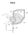
- a developer container 53 holds a magnetic toner 54 as the one component type developer, and electric charge having a reverse polarity to the electric charge of the electrostatic image formed on a photosensitive drum 51 and to the development standard potential is imparted to magnetic toner particles by the friction between particles of the magnetic toner and the friction between a developing sleeve 58 as a developer carrying member and the magnetic toner particles; the magnetic toner thus charged is very thin coated on the developing sleeve 58 by means of a magnetic blade 52 and then transported to the developing zone, D, defined by the photosensitive drum 51 and the developing sleeve 58; in the developing zone D, the magnetic toner is attracted by the action of a magnetic field formed by a magnet 55 stationarily set on the developping sle
- letter symbols A and B denote the directions of rotation of the developing sleeve 58 and the developing assembly 51, respectively.
- Reference numeral 59 denotes a development bias means for applying a development bias voltage at the time of development; and 60, an agitating element for agitating the magnetic toner 54 inside the developer container 53.
- the toner coated on the developing sleeve comes to have a too large charge quantity due to contact with the developing sleeve, so that the toner and the developing sleeve surface attract each other on account of the reflective force and the toner turns immobile on the surface of the developing sleeve.
- This is what is called the phenomenon of "charge-up", which especially tends to occur in an environment of low humidity.
- the toner forming an upper layer on the sleeve is difficult to charge so that the quantity of toner participating in development is lowered, raising such problems that line images are made thinner or solid-image density is reduced.
- the toner layer may be formed in a different state at image areas (where toner is consumed) and non-image areas to have been charged in different conditions, and hence, for example, if the position where a solid image with a high image density has been once formed by development comes to the development position on the next rotation of the developing sleeve and a latent halftone image is developed at that position, a mark of the solid image may appear on the image. Such a phenomenon, what is called “sleeve ghost", is liable to occur.
- toners have been made to have smaller particle diameters and made finer.
- toners in order to improve resolution and sharpness and faithfully reproduce latent images, it is common to use toners with a weight average particle diameter of about 6 to 9 ⁇ m.
- the toner is more liable to electrostatically adhere onto the developing sleeve and when external physical force is applied, the surface of the developing sleeve may be contaminated and the toner may be melt-adhered.
- a developing sleeve having a metal substrate provided with a coat layer formed of a resin in which a solid lubricant and a conductive fine powder such as carbon powder are dispersed.
- the use of this method can be seen to greatly reduce the occurrence of the above phenomenons.
- the surface shape of the developing sleeve is uneven and hence uniform charging still cannot be achieved sufficiently, leaving such problems on durability or running performance that the coat layer may become brittle.
- Japanese Patent Application Laid-open No. 3-200986 discloses a developing sleeve comprising a metal substrate provided with a conductive coat layer formed of a resin in which a solid lubricant, a conductive fine powder such as carbon powder and also spherical particles are dispersed.
- a developing sleeve comprising a metal substrate provided with a conductive coat layer formed of a resin in which a solid lubricant, a conductive fine powder such as carbon powder and also spherical particles are dispersed.
- the shape of the developing sleeve surface is made uniform, the charging is uniform and wear resistance is improved.
- its running performance is sought to be more improved, e.g., in wear resistance of the conductive coat layer and prevention of toner contamination and melt-adhesion of toner when the sleeve has worn.
- An object of the present invention is to provide a developer carrying member in which a conductive coat layer formed on its surface is less deteriorated due to repeated copying or running, which has a high durability and can give stable images; and a developing assembly, an image forming apparatus and a process cartridge which have such a developer carrying member.
- Another object of the present invention is to provide a developer carrying member which may cause no problems such as density decrease, sleeve ghost and fogging over a long period of time under various environmental conditions and can stably give high-grade images; and a developing assembly, an image forming apparatus and a process cartridge which have such a developer carrying member.
- Still another object of the present invention is to provide a developer carrying member which can inhibit uneven charging of toner on the developer carrying member surface when toners having small particle diameters are used, and can impart charges to toners in a proper quantity; and a developing assembly, an image forming apparatus and a process cartridge which have such a developer carrying member.
- a developer carrying member comprising a substrate the surface of which is covered with a conductive coat layer, wherein;
- the conductive coat layer contains at least a binder resin and conductive spherical particles dispersed therein having a number average particle diameter of from 0.3 ⁇ m to 30 ⁇ m and a true density of 3 g/cm 3 or below.
- the present invention also provides a developing assembly comprising;
- the present invention further provides an image forming apparatus comprising;
- the present invention still further provides a process cartridge detachably mountable on a main assembly of an image forming apparatus, comprising;
- Fig. 1 is a schematic drawing illustrating a developing assembly according to an embodiment of the present invention, having a developer carrying member which has a conductive coat layer.
- Fig. 2 is a schematic drawing illustrating a developing assembly according to another embodiment of the present invention, having a different developer layer thickness control member in the developing assembly shown in Fig. 1.
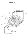
- Fig. 3 is a schematic drawing illustrating a developing assembly according to a still another embodiment of the present invention, having a different developer layer thickness control member in the developing assembly shown in Fig. 1.
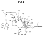
- Fig. 4 is a schematic drawing illustrating an image forming apparatus of the present invention.
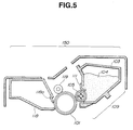
- Fig. 5 is a schematic drawing illustrating an example of the process cartridge of the present invention.
- Fig. 6 is a schematic drawing illustrating a conventional developing assembly having a developer carrying member which has no resin coat layer.
- the developer carrying member of the present invention is provided with a specific conductive coat layer on its surface, whereby its durability can be more greatly improved than those conventionally used, and the conductive coat layer on the surface of the developer carrying member may be less worn and deteriorated, not causing toner contamination. Hence, high-grade images can be provided over a long period of time substantially without causing decrease in image density and occurrence of ghost and fogging.
- Conductive spherical particles used in the conductive coat layer that covers the surface of a substrate constituting the developer carrying member of the present invention will be described.
- the conductive spherical particles used in the present invention have a number average particle diameter of from 0.3 ⁇ m to 30 ⁇ m, and preferably from 2 ⁇ m to 20 ⁇ m, and a true density of 3 g/cm 3 or below.
- Such conductive spherical particles are added so that the surface of the conductive coat layer in the developer carrying member of the present invention can retain a uniform surface roughness and also, even when the surface of the conductive coat layer has worn, the surface roughness of the conductive coat layer may less change so that contamination by toner and melt-adhesion of toner on the developer carrying member hardly occur.
- Conductive spherical particles having a number average particle diameter smaller than 0.3 ⁇ m are not preferable because the uniform roughness cannot be effectively imparted to the surface of the conductive coat layer, and the charge-up of toner, contamination by toner and melt-adhesion of toner may occur because of the wear of the conductive coat layer to result in poor images due to sleeve ghost and a decrease in image density.
- Those having a number average particle diameter larger than 30 ⁇ m also are not preferable because the conductive coat layer may have a too great roughness to make it difficult for the toner to be charged well and to cause a decrease in mechanical strength of the conductive coat layer.
- the "spherical" in the conductive spherical particles refers to particles having a major axis/minor axis ratio of from about 1.0 to 1.5. It is preferable to use particles having a major axis/minor axis ratio of from 1.0 to 1.2, and particularly to use truely spherical particles.
- Conductive spherical particles having a major axis/minor axis ratio higher than 1.5 are not preferable in view of uniform charging of the toner and strength of the conductive coat layer, because the dispersibility of the conductive spherical particles in the conductive coat layer may be lowered and also the surface roughness of the conductive coat layer may be non-uniform.
- the particles may have a volume resistivity of 10 6 ⁇ cm or below, and preferably a volume resistivity of from 10 3 ⁇ cm to 10 -6 ⁇ cm.
- Conductive spherical particles having a volume resistivity higher than 10 6 ⁇ cm are not preferable because spherical particles laid bare to the surface of the conductive coat layer as a result of wear may serve as nuclei to cause toner contamination and melt-adhesion.
- the conductive spherical particles used in the present invention have a true density of 3 g/cm 3 or below, preferably 2.7 g/cm 3 or below, and more preferably from 0.9 to 2.7 g/cm 3 .
- Conductive spherical particles having a true density exceeding 3 g/cm 3 or below are not preferable because the dispersibility of the spherical particles in the conductive coat layer is insufficient so that a uniform roughness may not be imparted to the surface of the coat layer, resulting in an insufficient uniform charging of the toner and strength of the coat layer.
- the conductive spherical particles used in the present invention may preferably be obtained by methods as described below, but not limited thereto.
- a method for obtaining particularly preferable conductive spherical particles used in the present invention there is, for example, a method in which spherical resin particles or mesocarbon microbeads are fired and thereby converted into carbon particles and/or graphite particles to obtain spherical carbon particles having a low density and a good conductivity.
- Resin used as the spherical resin particles may include, for example, phenol resins, naphthalene resins, furan resins, xylene resins, divinylbenzene polymers, styrene-divinylbenzene copolymers, and polyacrylonitrile.
- the mesocarbon microbeads can be usually produced by subjecting spherical crystals formed in the course of heating and firing a mesopitch, to washing with a large quantity of tar middle oil or solvent such as quinoline.
- the method may more preferably include a method in which the surfaces of spherical particles, such as phenol resin, naphthalene resin, furan resin, xylene resin, divinylbenzene polymer, styrene-divinylbenzene copolymer or polyacrylonitrile particles, are coated with bulk-mesophase pitch by a mechanochemical method, and the particles thus coated are heated in an oxidative atmosphere, followed by firing so as to be converted into carbon particles and/or graphite particles to give conductive spherical carbon particles.
- spherical particles such as phenol resin, naphthalene resin, furan resin, xylene resin, divinylbenzene polymer, styrene-divinylbenzene copolymer or polyacrylonitrile particles
- the conductivity of the spherical carbon particles can be controlled to a certain degree by changing conditions for firing, and such particles are preferably used in the present invention.
- the spherical carbon particles obtained by the above methods may optionally be coated with conductive metal and/or metal oxide to such an extent that the true density of the conductive spherical particles does not exceed 3 g/cm 3 .
- the conductive spherical particles used in the present invention there is a method in which core particles comprised of spherical resin particles and conductive fine particles having smaller particle diameters than the core particles are mechanically mixed in a suitable mixing ratio to cause the conductive fine particles to uniformly adhere to the peripheries of the core particles by the action of van der Waals force and electrostatic force, and thereafter the surfaces of the core particles are softened by local temperature rise caused by imparting mechanical impact so that the conductive fine particles form coats on the core particle surfaces, obtaining spherical resin particles subjected to conducting treatment.
- Resin for such particles may include, for example, PMMA, acrylic resins, polybutadiene resins, polystyrene resins, polyethylenes, polypropylenes, polybutadienes, or copolymers of any of theses, benzoguanamine resins, phenol resins, polyamide resins, nylons, fluorine resins, silicone resins, epoxy resins and polyester resins.
- coat particles used when coats are formed on the core particles (base particles)
- coat particles having a particle diameter of 1/8 or less of the base particles so that the coats of conductive fine particles can be uniformly provided.
- conductive fine particles are uniformly dispersed in spherical resin particles to give conductive spherical particles with the conductive fine particles dispersed therein.
- a method for uniformly dispersing the conductive fine particles in the spherical resin particles there is, for example, a method in which a binder resin and conductive fine particles are kneaded to disperse the latter in the former, and thereafter the product is pulverized into particles having a given particle diameter, followed by mechanical treatment and thermal treatment to make the particles spherical; and a method in which a polymerization initiator, conductive fine particles and other additives are added in polymerizable monomers and uniformly dispersed therein by means of a dispersion machine to give a monomer composition, followed by suspension polymerization in an aqueous phase containing a dispersion stabilizer by means of a stirrer so as to provide a given particle diameter, obtaining spherical particles with conductive fine particles dispersed therein.
- the conductive spherical particles with the conductive fine particles dispersed therein, obtained by this method may be further mechanically mixed with additional conductive fine particles having smaller particle diameters than the core particles, in a suitable mixing ratio to cause the additional conductive fine particles to uniformly adhere to the peripheries of the spherical resin particles by the action of van der Waals force and electrostatic force, and thereafter the surfaces of the resin particles with the conductive fine particles dispersed therein are softened by local temperature rise caused by imparting mechanical impact so that the additional conductive fine particles form coats on the resin particle surfaces, obtaining spherical resin particles with a higher conductivity.
- a lubricating material may be dispersed while used in combination with the conductive spherical particles. This is preferable since the present invention can be made more effective.
- Such lubricating material may include, for example, graphite, molybdenum disulfide, boron nitride, mica, graphite fluoride, silver-niobium selenide, calcium chloride-graphite, talc, and fatty acid metal salts such as zinc stearate.
- graphite is particularly preferable because conductivity of the conductive coat layer is not deteriorated when used in combination with the conductive spherical particles.
- this lubricating material those having a number average particle diameter of preferably from 0.2 to 20 ⁇ m, and more preferably from 1 to 15 ⁇ m, may be used.
- Lubricating materials having a number average particle diameter smaller than 0.2 ⁇ m are not preferable because the addition of the lubricating material can not be well effective. Those having a number average particle diameter larger than 20 ⁇ m are not preferable in view of uniform charging of the toner and strength of the conductive coat layer, because the surface roughness of the conductive coat layer may be non-uniform.
- the conductive coat layer constituting the developer carrying member of the present invention is formed by dispersing in the binder resin the conductive spherical particles and lubricating material as described above.
- the binder resin used herein it is possible to use, e.g., thermoplastic resins such as styrene resins, vinyl resins, polyether sulfone resin, polycarbonate resin, polyphenylene oxide resin, polyamide resins, fluorine resins, cellulose resins and acrylic resins; and photo- or heat-curable resins such as epoxy resins, polyester resins, alkyd resins, phenol resins, melamine resins, polyurethane resins, urea resins, silicone resins and polyimide resins.
- silicone resins and fluorine resins examples include those having release properties, such as silicone resins and fluorine resins, and those having good mechanical properties, such as polyether sulfone, polycarbonate, polyphenylene oxide, polyamide, phenol, polyester, polyurethane, styrene resins and acrylic resins.
- the conductive coat layer of the developer carrying member may preferably have a volume resistivity of 10 3 ⁇ cm or below, and more preferably from 10 3 to 10 -2 ⁇ cm.
- the conductive coat layer has a volume resistivity exceeding 10 3 ⁇ cm, the charge-up of toner tends to occur, so that ghost or density decrease is liable to occur.
- different conductive fine particles may be dispersed and incorporated into the conductive coat layer while used in combination with the conductive spherical particles described above.
- Such different conductive fine particles may preferably be those having a number average particle diameter of 1 ⁇ m or smaller, and more preferably from 0.01 to 0.8 ⁇ m.
- the different conductive fine particles dispersed and incorporated into the conductive coat layer, used in combination with the conductive spherical particles have a number average particle diameter larger than 1 ⁇ m, it may become difficult to control the volume resistivity of the conductive coat layer to be low, and cause the charge-up of toner is liable to occur.
- the conductive fine particles usable in the present invention may include, for example, carbon blacks such as furnace black, lamp black, thermal black, acetylene black and channel black; metal oxides such as titanium oxide, tin oxide, zinc oxide, molybdenum oxide, potassium titanate, antimony oxide and indium oxide; fine particles of metals such as aluminum, copper, silver and nickel; and inorganic fillers such as graphite, conductive metal fibers and conductive carbon fibers.
- carbon blacks such as furnace black, lamp black, thermal black, acetylene black and channel black
- metal oxides such as titanium oxide, tin oxide, zinc oxide, molybdenum oxide, potassium titanate, antimony oxide and indium oxide
- fine particles of metals such as aluminum, copper, silver and nickel
- inorganic fillers such as graphite, conductive metal fibers and conductive carbon fibers.
- the developer carrying member of the present invention is constituted as below.
- the developer carrying member of the present invention is mainly comprised of a metal cylinder serving as the substrate, and the conductive coat layer which covers the metal cylinder along its periphery.
- a metal cylinder serving as the substrate
- the conductive coat layer which covers the metal cylinder along its periphery.
- the metal cylinder a stainless steel cylinder and an aluminum cylinder are preferably used.
- the conductive spherical particles dispersed in the conductive coat layer may preferably be in a content of from 2 to 120 parts by weight, and preferably from 2 to 80 parts by weight, based on 100 parts by weight of the binder resin, which range gives particularly preferable results. If the conductive spherical particles are in a content less than 2 parts by weight, the addition of the conductive spherical particles can be less effective. If they are in a content more than 120 parts by weight, the charging performance of the toner may become too low.
- the lubricating material may preferably be in a content of from 5 to 120 parts by weight, and more preferably from 10 to 100 parts by weight, based on 100 parts by weight of the binder resin, which range gives particularly preferable results. If the lubricating material is in a content more than 120 parts by weight, the coat strength may be lowered and the charge quantity of the toner may be reduced. If it is in a content less than 5 parts by weight, the surface of the conductive coat layer may be contaminated by the toner.
- the conductive fine particles When the conductive fine particles are incorporated in the conductive coat layer while used in combination with the conductive spherical particles, the conductive fine particles may preferably be in a content not more than 40 parts by weight, and more preferably from 2 to 35 parts by weight, based on 100 parts by weight of the binder resin, which range gives particularly preferable results. Use of the conductive fine particles in a content more than 40 parts by weight is not preferable because the coat strength may be lowered and the charge quantity of the toner may be reduced.
- the conductive fine particles dispersed and incorporated in the conductive coat layer while used in combination with the conductive spherical particles may preferably have a number average particle diameter of 1 ⁇ m or smaller.
- the conductive coat layer may preferably have a surface roughness, as centerline average height (hereinafter “Ra”), within the range of from 0.2 to 4.5 ⁇ m, and more preferably within the range of from 0.4 to 3.5 ⁇ m.
- Ra centerline average height
- the conductive coat layer has an Ra less than 0.2 ⁇ m, the ability of the toner to be transported is lowered so that a sufficient image density may not be obtained. If the conductive coat layer has an Ra exceeding 4.5 ⁇ m, the transport quantity of the toner is so large that the toner cannot be charged sufficiently. Thus, such Ra are not preferable.
- the conductive coat layer constituted as described above may preferably have a layer thickness of 25 ⁇ m or less, more preferably 20 ⁇ m or less, and still more preferably from 4 to 20 ⁇ m. Such a thickness is preferable for obtaining a uniform layer thickness. The thickness is not particularly limited to this layer thickness.
- Fig. 1 schematically illustrates a developing assembly according to an embodiment of the present invention, having the developer carrying member.
- a latent image bearing member e.g., an electrophotographic photosensitive drum 1, having an electrostatic latent image formed by a known process is rotated in the direction of an arrow B.
- a developing sleeve 8 as the developer carrying member carries a one component type developer 4 having a magnetic toner, fed by a hopper serving as the developer container, and is rotated in the direction of an arrow A.
- the developer 4 is transported to the developing zone D where the developing sleeve 8 and the photosensitive drum 1 face each other.
- a magnet roller 5 inside the developing sleeve 8, a magnet roller 5 internally provided with a magnet is provided so that the developer 4 is magnetically attracted and held onto the developing sleeve 8.
- the developing sleeve 8 used in the developing assembly of the present invention has a conductive coat layer 7 covering a metal cylinder 6 of the substrate. Inside the hopper 3, a stirring wing 10 for stirring the developer 4 is provided. Reference numeral 12 denotes a gap, showing that the developing sleeve 8 and the magnet roller are not in contact with each other.
- the developer 4 gains triboelectric charges enabling development of the electrostatic latent image on the photosensitive drum 1, as a result of the friction between the particles of the magnetic toner and between the toner particles and the conductive coat layer 7 on the developing sleeve 8.
- a magnetic control blade 2 made of a ferromagnetic metal, serving as a developer layer thickness control member, vertically extends downwards from the hopper 3 in such a manner that its lower end faces the developing sleeve 8, leaving a gap of about 50 to 500 ⁇ m wide.
- the magnetic lines of force exerted from a magnetic pole N1 of the magnet roller 5 are converged to the magnetic control blade 2 to form on the developing sleeve 8 a thin layer of the developer 4.
- a non magnetic blade may also be used in place of the magnetic control blade 2.
- the thickness of the thin layer of the developer 4, thus formed on the developing sleeve 8, may preferably be smaller than the minimum gap between the developing sleeve 8 and the photosensitive drum in the developing zone D.
- Incorporation of the developer carrying member is particualrly effective in a type of a developing assembly in which electrostatic latent images are developed through such a developer thin layer, i.e., a non-contact type developing assembly.
- the developer carrying member of the present invention may also be applied in a type of developing assembly in which the thickness of the developer layer is larger than the minimum gap between the developing sleeve 8 and the photosensitive drum in the developing zone D, i.e., a contact type developing assembly.
- the non-contact developing assembly as described above is taken as an example in the following description.
- a development bias voltage is applied to the developing sleeve through a power source serving as a bias applying means.
- a voltage having a value intermediate between the potential at electrostatic latent image areas (the region rendered visible upon attraction of the developer 4) and the potential at back ground areas may preferably be applied to the developing sleeve 8.
- an alternating bias voltage may be applied to the developing sleeve 8 to form in the developing zone D a vibrating electric field whose direction alternately reverses.
- an alternating bias voltage formed by superimposing the above DC voltage component having a value intermediate between the potential at image areas to be developed and the potential at back ground areas may preferably be applied to the developing sleeve 8.
- Fig. 2 schematically illustrates the construction of a developing assembly according to another embodiment of the present invention.
- Fig. 3 schematically illustrates the construction of a developing assembly according to still another embodiment of the present invention.
- the developing assemblies shown in Figs. 2 and 3 use an elastic control blade 11 comprised of a material having rubber elasticity, such as urethane rubber or silicone rubber, or a material having metal elasticity, such as phosphor bronze or stainless steel, as the developer layer thickness control member to control the layer thickness of the magnetic toner 4 on the developing sleeve 8.
- this elastic control blade 11 is brought into press-contact with the developing sleeve 8 in the same direction as its rotational direction.
- this elastic control blade 11 is brought into press-contact with the developing sleeve 8 in the direction reverse to its rotational direction.
- the developer layer thickness control member is elastically brought into press-contact with the developing sleeve 8 through the developer layer to form the thin layer of the developer on the developing sleeve.
- a much thinner developer layer than the case aforementioned with reference to Fig. 1 can be formed on the developing sleeve 8.
- the developing assemblies shown in Figs. 2 and 3 have the same basic construction as the developing assembly shown in Fig. 1, and the same reference numerals denote basically the same members.
- Figs. 1 to 3 schematically exemplify the developing assembly of the present invention.
- the developer container the hopper 3
- the stirring member 10 the arrangement of magnetic poles.
- these assemblies can also be used in development employing a two component type developer comprised of a toner and a carrier.
- the surface of a photosensitive drum 101 as an electrostatic image bearing member is negatively charged by a contact (roller) charging means 102 as a primary charging means, and exposed to laser light 115 to form a digital latent image by image scanning.
- the latent image thus formed is developed by reversal development using a one component type developer having a magnetic toner, which is held in a developing assembly having equipped with a magnetic blade 11 and a developing sleeve 108 as a developer carrying member, internally provided with a magnet 105.
- the conductive substrate of the photosensitive drum 101 is earthed, and an alternating bias, a pulse bias and/or a DC bias is/are applied to the developing sleeve 108 through a bias applying means 109.
- a recording medium P is fed and delivered to the transfer zone, where the recording medium P is electrostatically charged by a contact (roller) transfer means 113 serving as a transfer means, on its back surface (the reverse side with respect to the photosensitive drum side) through a voltage applying means 114, so that the developed image (toner image) on the surface of the photosensitive drum 101 is transferred to the recording medium P through the contact transfer means 113.
- the recording medium P separated from the photosensitive drum 10 is subjected to fixing using a heat-pressure roller fixing assembly 7 serving as a fixing means, in order to fix the toner image on the recording medium P.
- the one component type developer 104 remaining on the photosensitive drum 101 after the step of transfer is removed by a cleaning means having a cleaning blade 118a.
- the cleaning step may be omitted.
- the residual charge on the surface of the photosensitive drum 101 is eliminated by erase exposure 116, and thus the procedure again starting from the charging step using the primary charging assembly 119 is repeated.
- the photosensitive drum 101 i.e., the latent image bearing member comprises a photosensitive layer and a conductive substrate, and is rotated in the direction of an arrow.
- the developing sleeve 108 formed of a non-magnetic cylinder, which is the developer carrying member, is rotated so as to move in the same direction as the surface movement of the photosensitive drum 101 in the developing zone.
- a multi-polar permanent magnet 105 (magnet roll) serving as a magnetic field generating means is provided in a non-rotatable state.
- the one component type developer 104 held in the developing assembly 103 is applied on the surface of the developing sleeve 108, and, for example, negative triboelectric charges are imparted to the magnetic toner as a result of the friction between its toner particles and the surface of the developing sleeve 108 and between particles of the magnetic toner.
- An elastic control blade 111 is also disposed so as to press the developing sleeve 108.
- the thickness of developer layer is controlled to be small (30 ⁇ m to 300 ⁇ m) and uniform so that a magnetic toner layer with a thickness smaller than the gap between the photosensitive drum 101 and the developing sleeve 108 in the developing zone is formed.
- the rotational speed of this developing sleeve 108 is regulated so that the peripheral speed of the developing sleeve 108 can be substantially equal or close to the peripheral speed of the photosensitive drum 101.
- an AC bias or a pulse bias may be applied as development bias voltage, to the developing sleeve 108 through a bias means 109.
- This AC bias may have a frequency (f) of 200 to 4,000 Hz and a Vpp of 500 to 3,000 V.
- the magnetic toner When the magnetic toner is moved in the developing zone, the magnetic toner is moved to the side of the electrostatic latent image by the electrostatic force of the surface of the photosensitive drum 10 and the action of the development bias voltage such as AC bias or pulse bias.
- the development bias voltage such as AC bias or pulse bias.
- the primary charging means has been described with reference to the charging roller as the contact charging means, it may also be a contact charging means such as a charging blade or a charging brush, as well as a non-contact corona charging means.
- the contact charging means is preferred in view of less ozone caused by charging.
- the transfer means has been described with reference to a contact transfer means such as the transfer roller, but it may also be a non-contact corona transfer means.
- the contact transfer means is preferred in view of less ozone caused by charging.
- Fig. 5 illustrates an embodiment of the process cartridge of the present invention.
- the developing means and the latent image bearing member are joined together into one unit to be a cartridge, and the process cartridge is provided detachably in the body of the image forming apparatus (e.g., a copying machine, a laser beam printer or a facsimile machine).
- the image forming apparatus e.g., a copying machine, a laser beam printer or a facsimile machine.
- a process cartridge 109 is exemplified in which a developing means 108, a drumlike latent image bearing member (a photosensitive drum) 101, a cleaning means 118 having a cleaning blade 118a and a primary charging means (a charging roller) 119 are joined into one unit.
- the developing means 109 has in a developer container 103 an elastic blade 111 and a one component type developer 104 having a magnetic toner.
- a given electric field is formed between the photosensitive drum 101 and the developing sleeve 105 by applying a development bias voltage from a bias applying means, carrying out the developing step by the use of the developer.
- the distance between the photosensitive drum 101 and the developing sleeve 105 is very important.
- the process cartridge has been described in which the four constituents, the developing means, the latent image bearing member, the cleaning means and the primary charging means, are joined together into one unit to be a cartridge.
- at least two constituents, the developing means and the latent image bearing member are joined together into one unit to be a cartridge.
- three constituents consisting of the developing means, the latent image bearing member and the cleaning means, and three constituents consisting of the developing means, the latent image bearing member and the primary charging means may be used while optionally adding other constituent(s), so that they are made together into one unit to constitute one cartridge.
- the developer (toner) used to visualize the electrostatic latent image will be described below.
- Toners to be contained in developers are generally classified into dry process toners and wet process toners.
- the wet process toners have a great problem concerning on the evaporation of solvents.
- the dry process toners are prevailing.
- the toner is a fine powder chiefly obtained by melt-kneading materials such as a binder resin, a release agent, a charge control agent and a colorant, and cooling the kneaded product to solidify, followed by pulverization and classification to make particle size distribution uniform.
- the binder resin used for the toner may include, for example, styrene, homopolymers of styrene or derivatives thereof such as ⁇ -methylstyrene and p-chlorostyrene; styrene copolymers such as a styrene-propylene copolymer, a styrene-vinyltoluene copolymer, a styrene-ethyl acrylate copolymer, a styrene-butyl acrylate copolymer, a styrene-octyl acrylate copolymer, a styrene-dimethylaminoethyl copolymer, a styrene-methyl methacrylate copolymer, a styrene-ethyl methacrylate copolymer, a styrene-butyl methacrylate
- a dye or pigment may be contained as a colorant in the toner.
- the dye or pigment may include, for example, carbon black, Nigrosine dyes, lamp black, Sudan Black SM, Fast Yellow G, Benzidine Yellow, Pigment Yellow, Indian First Orange, Irgazine Red, Para Nitraniline Red, Toluidine Red, Carmine 6B, Permanent Bordeaux F3R, Pigment Orange R, Lithol Red 2G, Lake Red 2G, Rhodamine FB, Rhodamine B Lake, Methyl Violet B lake, Phthalocyanine Blue, Pigment Blue, Brilliant Green B, Phthalocyanine Green, Oil Yellow GG, Zapon First Yellow CGG, Kayaset Y963, Kayaset YG, Zapon First Orange RR, Oil Scarlet, Aurazole Brown B, Zapon First Scarlet CG, and Oil Pink OP, any of which may be used under appropriate selection.
- a magnetic powder is incorporated in the toner.
- the magnetic powder a material magnetizable when placed in a magnetic field is used. It may include, for example, powders of ferromagnetic metals such as iron, cobalt and nickel; and alloys or compounds such as magnetite, hematite and ferrite. Such a magnetic powder may preferably be in a content of approximately from 15 to 70% by weight based on the weight of the toner.
- a release agent of various types is optionally added and incorporated in the toner.
- a release agent may include polyfluoroethylene, fluorine resins, fluorocarbon oil, silicone oil, low-molecular weight polyethylene, low-molecular weight polypropylene and various types of waxes.
- a charge control agent of various types may be added in order to make it easy for the toner to be charged positively or negatively.
- the non-magnetic toner as described above may be blended with a carrier so as to be used as a two component type developer, or, without being blended with a carrier, may be used as a one component type developer.
- the magnetic toner as described above may also be used as a one component type developer.
- the present invention Compared with developer carrying members conventionally used, the present invention enables more improved running performance (or durability) and maintenance of such a state that good images can be provided over a long period of time.
- the conductive coat layer on the surface of the developer carrying member is hardly deteriorated by, for example, wear and toner contamination due to repeated copying or running.
- high-grade images free of decrease in image density and occurrence of ghost and fogging can be provided over a long period of time.
- the 100 parts of spherical phenol resin particles with a number average particle diameter of 10 ⁇ m was uniformly coated with 14 parts of coal bulk-mesophase pitch powder with a number average particle diameter smaller than 3 ⁇ m by means of an automated mortar (manufactured by Ishikawa Kogyo). Thereafter, the coated particles were subjected to thermal stabilization treatment in an oxidative atmosphere, followed by firing at 2,200°C and graphitizing to give spherical, conductive carbon particles, which were used as conductive spherical particles A-1. Physical properties of the conductive spherical particles A-1 are shown in Table 1. Resol type phenol resin solution (containing 50% of methanol) 200 parts Graphite with number average particle diameter of 6.1 ⁇ m 45 parts Conductive carbon black 5 parts Isopropyl alcohol 130 parts
- zirconia beads of 1 mm diameter were added as media particles, and the dispersed for 2 hours by means of a sand mill, followed by separation of the zirconia beads through a sieve to give base solution B-1.
- a conductive coat layer was formed by spraying on a cylinder of 16 mm diameter, made of aluminum. Subsequently, the coated cylinder was heated at 150°C for 30 minutes by means of a hot air drying oven to cure the conductive coat layer. Thus, developer carrying member C-1 was produced. The conductive coat layer after drying was in a coating weight of 100 mg. Physical properties of the conductive coat layer of this developer carrying member C-1 are shown in Table 2.
- the developer carrying member C-1 was used in a laser beam printer LASER JET III Si (manufactured by Hulett Packard Co.) as the image forming apparatus shown in Fig. 4, having the developing assembly shown in Fig. 3. Using this apparatus, a running evaluation test (examination for durability in operation for a long period of time) was carried out for the developer carrying member while feeding a one component type developer.
- LASER JET III Si manufactured by Hulett Packard Co.
- Styrene-acrylic resin 100 parts Magnetite 80 parts Chromium complex of 3,5-di-tert-butylsalicylic acid 2 parts Low-molecular weight polypropylene 4 parts
- the image forming apparatus used in the present Example has the constitution that the process cartridge comprised of the latent image bearing member, the developing means, the cleaning means and the primary charging means which are joined into one unit as a cartridge is detachably mounted on the body of the image forming apparatus.
- the 100 parts of spherical phenol resin particles with a number average particle diameter of 4.8 ⁇ m was coated uniforming with 14 parts of coal bulk-mesophase pitch powder with a number average particle diameter smaller than 1 ⁇ m by means of an automated mortar (manufactured by Ishikawa Kogyo).
- the coated particles were subjected to thermal stabilization treatment in an oxidative atmosphere, followed by firing at 2,200°C and graphitizing to give spherical, conductive carbon particles, which were used as conductive spherical particles A-2. Physical properties of the conductive spherical particles A-2 are shown in Table 1.
- Example 2 The subsequent procedure in Example 1 was repeated except that 25 parts of the conductive spherical particles A-2 were added to 380 parts of the base solution B-1 as prepared in Example 1, to produce developer carrying member C-2.
- the conductive coat layer after drying was in a coating weight of 105 mg. Physical properties of the conductive coat layer of this developer carrying member C-2 are shown in Table 2.
- the developer carrying member C-2 was used in the same image forming apparatus as in Example 1. In the same manner as in Example 1, a running evaluation test was carried out for the developer carrying member while feeding the one component type developer.
- the 100 parts of spherical phenol resin particles with a number average particle diameter of 26 ⁇ m was coated uniforming with 14 parts of coal bulk-mesophase pitch powder with a number average particle diameter smaller than 4 ⁇ m by means of an automated mortar (manufactured by Ishikawa Kogyo).
- the coated particles were subjected to thermal stabilization treatment in an oxidative atmosphere, followed by firing at 2,200°C and graphitizing to give spherical, conductive carbon particles, which were used as conductive spherical particles A-3. Physical properties of the conductive spherical particles A-3 are shown in Table 1.
- Example 2 The subsequent procedure in Example 1 was repeated except that 6 parts of the conductive spherical particles A-3 were added to 380 parts of the base solution B-1 as prepared in Example 1, to produce developer carrying member C-3.
- the conductive coat layer after drying was in a coating weight of 100 mg. Physical properties of the conductive coat layer of this developer carrying member C-3 are shown in Table 2.
- the C-3 developer carrying member was used in the same image forming apparatus as in Example 1. In the same manner as in Example 1, a running evaluation test was carried out for the developer carrying member while feeding the one component type developer.
- the 100 parts of spherical phenol resin particles with a number average particle diameter of 10 ⁇ m was coated uniformly with 14 parts of coal bulk-mesophase pitch powder with a number average particle diameter smaller than 3 ⁇ m by means of an automated mortar (manufactured by Ishikawa Kogyo) in the same manner as in Example 1.
- the coated particles were subjected to thermal stabilization treatment in an oxidative atmosphere, followed by firing at 1,000°C and carbonizing to give spherical, conductive carbon particles, which were used as conductive spherical particles A-4. Physical properties of the conductive spherical particles A-4 are shown in Table 1.
- Example 2 The subsequent procedure in Example 1 was repeated except that 10 parts of the conductive spherical particles A-4 were added to 380 parts of the base solution B-1 as prepared in Example 1, to produce developer carrying member C-4.
- the conductive coat layer after drying was in a coating weight of 95 mg. Physical properties of the conductive coat layer of this developer carrying member C-4 are shown in Table 2.
- the developer carrying member C-4 was used in the same image forming apparatus as in Example 1. In the same manner as in Example 1, a running evaluation test was carried out for the developer carrying member while feeding the one component type developer.
- Spherical phenol resin particles with a number average particle diameter of 10.0 ⁇ m were subjected, as they were, to thermal stabilization treatment in an oxidative atmosphere, followed by firing at 2,200°C and graphitizing to give spherical, conductive carbon particles, which were used as conductive spherical particles A-5.
- Physical properties of the conductive spherical particles A-5 are shown in Table 1.
- Example 2 The subsequent procedure in Example 1 was repeated except that 10 parts of the conductive spherical particles A-5 were added to 380 parts of the base solution B-1 as prepared in Example 1, to produce developer carrying member C-5.
- the conductive coat layer after drying was in a coating weight of 100 mg. Physical properties of the conductive coat layer of this developer carrying member C-5 are shown in Table 2.
- the C-5 developer carrying member was used in the same image forming apparatus as in Example 1. In the same manner as in Example 1, a running evaluation test was carried out for the developer carrying member while feeding the one component type developer.
- Spherical phenol resin particles with a number average particle diameter of 10.3 ⁇ m were subjected, as they were, to thermal stabilization treatment in an oxidative atmosphere, followed by firing at 1,000°C and carbonizing to give spherical, conductive carbon particles, which were used as conductive spherical particles A-6.
- Physical properties of the conductive spherical particles A-6 are shown in Table 1.
- Example 2 The subsequent procedure in Example 1 was repeated except that 10 parts of the conductive spherical particles A-6 were added to 380 parts of the base solution B-1 as prepared in Example 1, to produce developer carrying member C-6.
- the conductive coat layer after drying was in a coating weight of 95 mg. Physical properties of the conductive coat layer of this developer carrying member C-6 are shown in Table 2.
- the C-6 developer carrying member was used in the same image forming apparatus as in Example 1. In the same manner as in Example 1, a running evaluation test was carried out for the developer carrying member while feeding the one component type developer.
- the 100 parts of spherical divinylbenzene polymer particles with a number average particle diameter of 10.2 ⁇ m was uniformly coated with 14 parts of petroleum bulk-mesophase pitch powder with a number average particle diameter smaller than 3 ⁇ m by means of an automated mortar (manufactured by Ishikawa Kogyo).
- the coated particles were subjected to thermal stabilization treatment in an oxidative atmosphere, followed by firing at 2,000°C and graphitizing to give spherical, conductive carbon particles, which were used as conductive spherical particles A-7. Physical properties of the conductive spherical particles A-7 are shown in Table 1.
- Example 2 The subsequent procedure in Example 1 was repeated except that 10 parts of the conductive spherical particles A-7 were added to 380 parts of the base solution B-1 as prepared in Example 1, to produce developer carrying member C-7.
- the conductive coat layer after drying was in a coating weight of 105 mg. Physical properties of the conductive coat layer of this developer carrying member C-7 are shown in Table 2.
- the C-7 developer carrying member was used in the same image forming apparatus as in Example 1. In the same manner as in Example 1, a running evaluation test was carried out for the developer carrying member while feeding the one component type developer.
- Example 2 The subsequent procedure in Example 1 was repeated except that 10 parts of the conductive spherical particles A-8 were added to 380 parts of the base solution B-1 as prepared in Example 1, to produce developer carrying member C-8. Its conductive coat layer after drying was in a coating weight of 110 mg. Physical properties of the conductive coat layer of this developer carrying member C-8 are shown in Table 2.
- the developer carrying member C-8 was used in the same image forming apparatus as in Example 1. In the same manner as in Example 1, a running evaluation test was carried out for the developer carrying member while feeding the one component type developer.
- spherical PMMA particles with a number average particle diameter of 11.5 ⁇ m was coated with 5 parts of conductive carbon black by means of a hybridizer (manufactured by Nara Kikai) to give spherical resin particles subjected to conducting treatment, which were used as conductive spherical particles A-9.
- a hybridizer manufactured by Nara Kikai
- Physical properties of the conductive spherical particles A-9 are shown in Table 1.
- Example 2 The subsequent procedure in Example 1 was repeated except that 10 parts of the conductive spherical particles A-9 were added to 380 parts of the base solution B-1 as prepared in Example 1, to produce developer carrying member C-9.
- the conductive coat layer after drying was in a coating weight of 100 mg. Physical properties of the conductive coat layer of this developer carrying member C-9 are shown in Table 2.
- the C-9 developer carrying member was used in the same image forming apparatus as in Example 1. In the same manner as in Example 1, a running evaluation test was carried out for the developer carrying member while feeding the one component type developer.
- spherical PMMA particles with a number average particle diameter of 11.5 ⁇ m was coated with 20 parts of fine conductive zinc oxide particles by means of a hybridizer (manufactured by Nara Kikai) to give spherical resin particles subjected to conducting treatment, which were used as conductive spherical particles A-10.
- Physical properties of the conductive spherical particles A-10 are shown in Table 1.
- Example 2 The subsequent procedure in Example 1 was repeated except that 10 parts of the conductive spherical particles A-10 were added to 380 parts of the base solution B-1 as prepared in Example 1, to produce developer carrying member C-10.
- the conductive coat layer after drying was in a coating weight of 105 mg. Physical properties of the conductive coat layer of this developer carrying member C-10 are shown in Table 2.
- the C-10 developer carrying member was used in the same image forming apparatus as in Example 1. In the same manner as in Example 1, a running evaluation test was carried out for the developer carrying member while feeding the one component type developer.
- the 100 parts of spherical nylon particles with a number average particle diameter of 11.0 ⁇ m was coated with 18 parts of conductive graphite by means of a hybridizer (manufactured by Nara Kikai) to give spherical resin particles subjected to conducting treatment, which were used as conductive spherical particles A-11.
- Physical properties of the conductive spherical particles A-ll are shown in Table 1.
- Example 2 The subsequent procedure in Example 1 was repeated except that 10 parts of the conductive spherical particles A-11 were added to 380 parts of the B-1 base solution as prepared in Example 1, to produce developer carrying member C-11.
- the conductive coat layer after drying was in a coating weight of 100 mg. Physical properties of the conductive coat layer of this developer carrying member C-11 are shown in Table 2.
- the C-11 developer carrying member was used in the same image forming apparatus as in Example 1. In the same manner as in Example 1, a running evaluation test was carried out for the developer carrying member while feeding the one component type developer.
- Example 2 The subsequent procedure in Example 1 was repeated except that 10 parts of the conductive spherical particles A-12 were added to 380 parts of the base solution B-1 as prepared in Example 1, to produce developer carrying member C-12.
- the C-12 developer carrying member was used in the same image forming apparatus as in Example 1. In the same manner as in Example 1, a running evaluation test was carried out for the developer carrying member while feeding the one component type developer.
- Example 2 The subsequent procedure in Example 1 was repeated except that 10 parts of the conductive spherical particles A-13 were added to 380 parts of the base solution B-1 as prepared in Example 1, to produce developer carrying member C-13. Its conductive coat layer after drying was in a coating weight of 100 mg. Physical properties of the conductive coat layer of this developer carrying member C-13 are shown in Table 2.
- the C-13 developer carrying member was used in the same image forming apparatus as in Example 1. In the same manner as in Example 1, a running evaluation test was carried out for the developer carrying member while feeding the one component type developer.
- conductive particles with a number average particle diameter of 10.5 ⁇ m. Thereafter, the particles were made spherical by means of a hybridizer (manufactured by Nara Kikai) to gice conductive spherical resin particles, which were used as conductive spherical particles A-14. Physical properties of the conductive spherical particles A-14 are shown in Table 1. Styrene/dimethylaminoethyl methacrylate/divinylbenzene copolymer (copolymerization ratio: 90:10:0.05) 100 parts Fine silver particles 50 parts
- Example 2 The subsequent procedure in Example 1 was repeated except that 10 parts of the conductive spherical particles A-14 were added to 380 parts of the base solution B-1 as prepared in Example 1, to produce developer carrying member C-14.
- the conductive coat layer after drying was in a coating weight of 105 mg. Physical properties of the conductive coat layer of this developer carrying member C-14 are shown in Table 2.
- the C-14 developer carrying member was used in the same image forming apparatus as in Example 1. In the same manner as in Example 1, a running evaluation test was carried out for the developer carrying member while feeding the one component type developer.
- zirconia beads of 1 mm diameter were added as media particles, and the materials were dispersed for 2 hours by means of a sand mill, followed by separation of the zirconia beads through a sieve to obtain base solution B-2.
- Example 2 The subsequent procedure in Example 1 was repeated except that 10 parts of the conductive spherical particles A-1 were added to 380 parts of the base solution B-2 thus prepared, to produce developer carrying member C-15.
- the conductive coat layer after drying was in a coating weight of 100 mg. Physical properties of the conductive coat layer of this developer carrying member C-15 are shown in Table 2.
- the C-15 developer carrying member was used in the same image forming apparatus as in Example 1. In the same manner as in Example 1, a running evaluation test was carried out for the developer carrying member while feeding the one component type developer.
- PMMA resin solution (containing 50% of methanol) 200 parts Graphite with number average particle diameter of 6.1 ⁇ m 45 parts Conductive carbon black 5 parts Toluene 130 parts
- zirconia beads of 1 mm diameter were added as media particles, and the materials were dispersed for 2 hours by means of a sand mill, followed by separation of the zirconia beads through a sieve to obtain base solution B-3.
- Example 2 The subsequent procedure in Example 1 was repeated except that 10 parts of the conductive spherical particles A-1 were added to 380 parts of the base solution B-3 thus prepared, to produce developer carrying member C-16.
- the conductive coat layer after drying was in a coating weight of 105 mg. Physical properties of the conductive coat layer of this developer carrying member C-16 are shown in Table 2.
- the C-16 developer carrying member was used in the same image forming apparatus as in Example 1. In the same manner as in Example 1, a running evaluation test was carried out for the developer carrying member while feeding the one component type developer.
- Resol type phenol resin solution (containing 50% of methanol) 200 parts Graphite with number average particle diameter of 1.5 ⁇ m 30 parts Conductive carbon black 5 parts Isopropyl alcohol 130 parts
- zirconia beads of 1 mm diameter were added as media particles, and the materials were dispersed for 2 hours by means of a sand mill, followed by separation of the zirconia beads through a sieve to give base solution B-4.
- Example 2 To 380 parts of the base solution B-4 thus prepared, 15 parts of the conductive spherical particles A-2 as used in Example 2 were added, and isopropyl alcohol was added so as to provide a solid matter concentration of 32%. Thereafter, the particles were dispersed for 1 hour with addition of glass beads of 3 mm diameter, followed by separation of the glass beads through a sieve to give a coating solution.
- a conductive coat layer was formed by spraying on a cylinder of 32 mm diameter, made of aluminum. Subsequently, the coated cylinder was heated at 140°C for 30 minutes by means of a hot air drying oven to cure the conductive coat layer. Thus, developer carrying member C-17 was produced. The conductive coat layer after drying was in a coating weight of 265 mg. Physical properties of the conductive coat layer of this developer carrying member C-17 are shown in Table 2.
- the developer carrying member C-17 was used in a copying machine NP-6060 (manufactured by CANON INC.) as the image forming apparatus shown in Fig. 4 (corona charging means, corona transfer means), having the developing assembly shown in Fig. 1. Using this apparatus, a running evaluation test was carried out for the developer carrying member while feeding a one component type developer.
- Polyester resin 100 parts Magnetite 100 parts Chromium complex of 3,5-di-tert-butylsalicylic acid 2 parts Low-molecular weight polypropylene 4 parts
- Example 2 The procedure of Example 1 was repeated except that, in place of the conductive spherical particles A-1, 10 parts of amorphous graphite a-1 with a number average particle diameter of 17.0 ⁇ m was added to 380 parts of the base solution B-1 as prepared in Example 1, to produce developer carrying member D-1.
- the conductive coat layer after druing was in a coating weight of 100 mg. Physical properties of the conductive coat layer of this developer carrying member D-1 are shown in Table 2.
- the D-1 developer carrying member was used in the same image forming apparatus as in Example 1. In the same manner as in Example 1, a running evaluation test was carried out for the developer carrying member while feeding the one component type developer.
- Example 2 The procedure of Example 1 was repeated except that, in place of the conductive spherical particles A-1, 10 parts of non-conductive spherical PMMA particles a-2 with a number average particle diameter of 11.5 ⁇ m were added to 380 parts of the base solution B-1 as prepared in Example 1, to produce developer carrying member D-2.
- the conductive coat layer after drying was in a coating weight of 100 mg. Physical properties of the conductive coat layer of this developer carrying member D-2 are shown in Table 2.
- the developer carrying member D-2 was used in the same image forming apparatus as in Example 1. In the same manner as in Example 1, a running evaluation test was carried out for the developer carrying member while feeding the one component type developer.
- the 100 parts of spherical phenol resin particles with a number average particle diameter of 37 ⁇ m was coated uniformly with 16 parts of coal bulk-mesophase pitch powder with a number average particle diameter smaller than 4 ⁇ m by means of an automated mortar (manufactured by Ishikawa Kogyo).
- the coated particles were subjected to thermal stabilization treatment in an oxidative atmosphere, followed by firing at 2,200°C and graphitizing to give spherical, conductive carbon particles, which were used as conductive spherical particles a-3.
- Physical properties of the conductive spherical particles a-3 were as shown in Table 1; the conductive spherical particles a-3 had a number average particle diameter of 35 ⁇ m.
- Example 2 The subsequent procedure in Example 1 was repeated except that 5 parts of the conductive spherical particles a-3 were added to 380 parts of the base solution B-1 as prepared in Example 1, to produce developer carrying member D-3.
- the conductive coat layer after drying was in a coating weight of 105 mg. Physical properties of the conductive coat layer of this developer carrying member D-3 are shown in Table 2.
- the developer carrying member D-3 was used in the same image forming apparatus as in Example 1. In the same manner as in Example 1, a running evaluation test was carried out for the developer carrying member while feeding the one component type developer.
- the 100 parts of spherical PMMA particles with a number average particle diameter of 0.19 ⁇ m was coated 25 parts of conductive carbon black by means of a hybridizer (manufactured by Nara Kikai) to give spherical, conductive-treated resin particles, which were used as conductive spherical particles a-4.
- Physical properties of the conductive spherical particles a-4 were as shown in Table 1; the conductive spherical particles a-3 had a number average particle diameter of 0.23 ⁇ m.
- Example 2 The subsequent procedure in Example 1 was repeated except that, in place of the conductive spherical particles A-1, 35 parts of the conductive spherical particles a-4 were added to 380 parts of the base solution B-1 as prepared in Example 1, to produce developer carrying member D-4.
- the conductive coat layer after drying was in a coating weight of 105 mg. Physical properties of the conductive coat layer of this developer carrying member D-4 are shown in Table 2.
- the developer carrying member D-4 was used in the same image forming apparatus as in Example 1. In the same manner as in Example 1, a running evaluation test was carried out for the developer carrying member while feeding the one component type developer.
- conductive particles with a number average particle diameter of 10.7 ⁇ m. Thereafter, the particles were made spherical by means of a hybridizer (manufactured by Nara Kikai) to give conductive spherical resin particles, which were used as conductive spherical particles a-5.
- Physical properties of the conductive spherical particles A-5 were as shown in Table 1; the true density thereof was 3.35 g/cm 3 .
- Styrene/dimethylaminoethyl methacrylate/divinylbenzene copolymer (copolymerization ratio: 90:10:0.05) 100 parts Fine silver particles 300 parts
- Example 2 The subsequent procedure in Example 1 was repeated except that, in place of the conductive spherical particles A-1, 10 parts of the conductive spherical particles a-5 were added to 380 parts of the base solution B-1 as prepared in Example 1, to produce developer carrying member D-5.
- the conductive coat layer after drying was in a coating weight of 105 mg. Physical properties of the conductive coat layer of this developer carrying member D-5 are shown in Table 2.
- the developer carrying member D-5 was used in the same image forming apparatus as in Example 1. In the same manner as in Example 1, a running evaluation test was carried out for the developer carrying member while feeding the one component type developer.
- Example 2 The subsequent procedure in Example 1 was repeated except that, in place of the conductive spherical particles A-1, 10 parts of the conductive amorphous particles a-6 were added to 380 parts of the base solution B-1 as prepared in Example 1, to produce developer carrying member D-6.
- the conductive coat layer after drying was in a coating weight of 95 mg. Physical properties of the conductive coat layer of this developer carrying member D-6 are shown in Table 2.
- the developer carrying member D-6 was used in the same image forming apparatus as in Example 1. In the same manner as in Example 1, a running evaluation test was carried out for the developer carrying member while feeding the one component type developer.
- Example 17 The procedure of Example 17 was repeated except that, in place of the conductive spherical particles A-2, 15 parts of amorphous graphite with a number average particle diameter of 4.0 ⁇ m was added to 380 parts of the base solution B-4 as prepared in Example 17, to produce developer carrying member D-7.
- the conductive coat layer after drying was in a coating weight of 270 mg. Physical properties of the conductive coat layer of this developer carrying member D-7 are shown in Table 2.
- the developer carrying member D-7 was used in the same image forming apparatus as in Example 17. In the same manner as in Example 17, a running evaluation test was carried out for the developer carrying member while feeding the one component type developer.
- Table 3 shows the results of evaluation for durability of image density, and running fogging and ghost (which may occur after operation over a long period of time) in a low temperature and low humidity environment in respect of Examples and Comparative Examples.
- Table 4 shows the results of evaluation for durability of image density, running fog and running ghost in environment of high temperature and high humidity in respect of Examples and Comparative Examples.
- Table 5 The results of evaluation for wear resistance and anti-contamination properties in respect of Examples and Comparative Examples are shown in Table 5.
Landscapes
- Physics & Mathematics (AREA)
- General Physics & Mathematics (AREA)
- Dry Development In Electrophotography (AREA)
- Developing Agents For Electrophotography (AREA)
Applications Claiming Priority (3)
| Application Number | Priority Date | Filing Date | Title |
|---|---|---|---|
| JP33761694 | 1994-12-28 | ||
| JP33761694 | 1994-12-28 | ||
| JP337616/94 | 1994-12-28 |
Publications (3)
| Publication Number | Publication Date |
|---|---|
| EP0720070A2 true EP0720070A2 (fr) | 1996-07-03 |
| EP0720070A3 EP0720070A3 (fr) | 1997-01-02 |
| EP0720070B1 EP0720070B1 (fr) | 2001-08-16 |
Family
ID=18310333
Family Applications (1)
| Application Number | Title | Priority Date | Filing Date |
|---|---|---|---|
| EP95309446A Expired - Lifetime EP0720070B1 (fr) | 1994-12-28 | 1995-12-27 | Elément de transport de développateur, ensemble de développement, appareil de formation d'images et unité de traitement |
Country Status (3)
| Country | Link |
|---|---|
| US (1) | US5860050A (fr) |
| EP (1) | EP0720070B1 (fr) |
| DE (1) | DE69522194T2 (fr) |
Cited By (1)
| Publication number | Priority date | Publication date | Assignee | Title |
|---|---|---|---|---|
| GB2350694B (en) * | 1996-09-02 | 2001-05-09 | Bridgestone Corp | Manufacture of magnetic rollers for use in developing rollers and developing devices |
Families Citing this family (9)
| Publication number | Priority date | Publication date | Assignee | Title |
|---|---|---|---|---|
| JP2001083796A (ja) * | 1999-09-13 | 2001-03-30 | Canon Inc | 現像装置、プロセスカートリッジおよび画像形成装置 |
| JP3984833B2 (ja) | 2001-01-16 | 2007-10-03 | キヤノン株式会社 | 現像剤担持体の再生方法 |
| US6924076B2 (en) * | 2001-08-20 | 2005-08-02 | Canon Kabushiki Kaisha | Developing assembly, process cartridge and image-forming method |
| JP3943885B2 (ja) * | 2001-10-04 | 2007-07-11 | キヤノン株式会社 | 画像形成方法 |
| EP1308796B1 (fr) * | 2001-10-30 | 2013-04-24 | Canon Kabushiki Kaisha | Ensemble de développement, porteur de développateur contenant une couche de résine, appareil de formation d'images et unité de traitement |
| DE60301084T2 (de) * | 2002-05-07 | 2006-05-24 | Canon K.K. | Entwicklerträger, Entwicklungsapparatur worin dieser Entwicklerträger eingesetzt ist und Verfahrenskassette worin dieser Entwicklerträger eingesetzt ist |
| US7223511B2 (en) * | 2003-09-02 | 2007-05-29 | Canon Kabushiki Kaisha | Developer carrying member and developing method by using thereof |
| US7727619B2 (en) * | 2003-10-31 | 2010-06-01 | Canon Kabushiki Kaisha | Developer carrying member and developing apparatus |
| JP4448174B2 (ja) * | 2005-07-21 | 2010-04-07 | キヤノン株式会社 | 現像剤担持体及び現像装置 |
Family Cites Families (11)
| Publication number | Priority date | Publication date | Assignee | Title |
|---|---|---|---|---|
| US4034709A (en) * | 1975-10-22 | 1977-07-12 | Xerox Corporation | Developer roll |
| US4614682A (en) * | 1984-10-11 | 1986-09-30 | Ricoh Company, Ltd. | Thermosensitive image transfer recording medium |
| US4989044A (en) * | 1988-04-27 | 1991-01-29 | Canon Kabushiki Kaisha | Developing apparatus for developing electrostatic latent images |
| ATE154145T1 (de) * | 1989-07-28 | 1997-06-15 | Canon Kk | Bildherstellungsapparat |
| US5210617A (en) * | 1989-07-28 | 1993-05-11 | Canon Kabushiki Kaisha | Developer for developing electrostatic images and image forming apparatus |
| JPH0395574A (ja) * | 1989-09-08 | 1991-04-19 | Canon Inc | 現像剤担持体及びその製造方法 |
| DE69010607T2 (de) * | 1989-10-02 | 1994-12-01 | Canon Kk | Entwickler-Trägerelement, Entwicklungsvorrichtung und Einheit mit dieser Vorrichtung. |
| US5177537A (en) * | 1989-12-20 | 1993-01-05 | Canon Kabushiki Kaisha | Developing apparatus with elastic regulating member urged to a developer carrying member |
| US5202729A (en) * | 1990-10-26 | 1993-04-13 | Canon Kabushiki Kaisha | Developing apparatus having a coated developing roller |
| JP2715337B2 (ja) * | 1990-10-26 | 1998-02-18 | キヤノン株式会社 | 画像形成方法 |
| DE69226310T2 (de) * | 1991-05-29 | 1998-12-17 | Canon K.K., Tokio/Tokyo | Entwicklungsgerät und Entwicklerträgerelement dafür |
-
1995
- 1995-12-27 DE DE69522194T patent/DE69522194T2/de not_active Expired - Lifetime
- 1995-12-27 EP EP95309446A patent/EP0720070B1/fr not_active Expired - Lifetime
-
1997
- 1997-06-27 US US08/884,623 patent/US5860050A/en not_active Expired - Lifetime
Cited By (1)
| Publication number | Priority date | Publication date | Assignee | Title |
|---|---|---|---|---|
| GB2350694B (en) * | 1996-09-02 | 2001-05-09 | Bridgestone Corp | Manufacture of magnetic rollers for use in developing rollers and developing devices |
Also Published As
| Publication number | Publication date |
|---|---|
| DE69522194T2 (de) | 2002-04-18 |
| EP0720070A3 (fr) | 1997-01-02 |
| EP0720070B1 (fr) | 2001-08-16 |
| US5860050A (en) | 1999-01-12 |
| DE69522194D1 (de) | 2001-09-20 |
Similar Documents
| Publication | Publication Date | Title |
|---|---|---|
| US5998008A (en) | Developer carrying member, comprising a coat layer containing a conductive particle and a nitrogen-containing heterocyclic compound developing apparatus, developing method, image forming apparatus, and process cartridge | |
| EP0420197A2 (fr) | Méthode et appareil de formation d'images | |
| JPH1097097A (ja) | 静電荷潜像現像用磁性トナー、装置ユニット及び画像形成方法 | |
| EP0720070B1 (fr) | Elément de transport de développateur, ensemble de développement, appareil de formation d'images et unité de traitement | |
| JP3192363B2 (ja) | 現像剤担持体、現像装置、画像形成装置及びプロセスカートリッジ | |
| JPS5811621B2 (ja) | 複写方法 | |
| US8298658B2 (en) | Developer carrying member and developing assembly | |
| EP1528440B1 (fr) | Elément porteur de révelateur avec dispositif de développement | |
| JP3332727B2 (ja) | 画像形成方法及びトナー | |
| JP3245034B2 (ja) | 現像剤担持体および現像装置 | |
| JP2003323041A (ja) | 現像剤担持体および該現像剤担持体を用いた現像装置およびプロセスカートリッジ | |
| JP4035366B2 (ja) | 現像剤担持体、それを用いた現像装置及びプロセスカートリッジ | |
| JP2000242029A (ja) | 画像形成方法、画像形成装置及び画像形成用磁性トナー | |
| CA1112500A (fr) | Materiaux porteurs de particules isolantes et conductrices | |
| JP3302271B2 (ja) | 現像剤担持体及びこれを用いた現像装置 | |
| JP2003323040A (ja) | 現像剤担持体、それを用いた現像装置及びプロセスカートリッジ | |
| JPH10293454A (ja) | 現像剤担持体、現像装置、現像方法、画像形成装置及びプロセスカートリッジ | |
| JP3363726B2 (ja) | 現像剤担持体及びプロセスカートリッジ | |
| JP3123013B2 (ja) | 現像剤担持体及び現像装置 | |
| JP3271171B2 (ja) | 現像剤担持体及びそれを用いた現像装置 | |
| JP3984861B2 (ja) | 現像剤担持体及び該現像剤担持体を用いた現像装置及びプロセスカートリッジ | |
| JP3729718B2 (ja) | 静電荷像現像用トナーと画像形成方法 | |
| JP3486538B2 (ja) | 現像方法、現像装置及び画像形成方法 | |
| JP3643992B2 (ja) | 静電荷像現像用キャリア | |
| JP2002196580A (ja) | 現像剤担持体、及びそれを用いた現像装置 |
Legal Events
| Date | Code | Title | Description |
|---|---|---|---|
| PUAI | Public reference made under article 153(3) epc to a published international application that has entered the european phase |
Free format text: ORIGINAL CODE: 0009012 |
|
| AK | Designated contracting states |
Kind code of ref document: A2 Designated state(s): DE FR GB IT |
|
| PUAL | Search report despatched |
Free format text: ORIGINAL CODE: 0009013 |
|
| AK | Designated contracting states |
Kind code of ref document: A3 Designated state(s): DE FR GB IT |
|
| 17P | Request for examination filed |
Effective date: 19970514 |
|
| 17Q | First examination report despatched |
Effective date: 19980804 |
|
| GRAG | Despatch of communication of intention to grant |
Free format text: ORIGINAL CODE: EPIDOS AGRA |
|
| GRAG | Despatch of communication of intention to grant |
Free format text: ORIGINAL CODE: EPIDOS AGRA |
|
| GRAG | Despatch of communication of intention to grant |
Free format text: ORIGINAL CODE: EPIDOS AGRA |
|
| GRAH | Despatch of communication of intention to grant a patent |
Free format text: ORIGINAL CODE: EPIDOS IGRA |
|
| GRAH | Despatch of communication of intention to grant a patent |
Free format text: ORIGINAL CODE: EPIDOS IGRA |
|
| GRAA | (expected) grant |
Free format text: ORIGINAL CODE: 0009210 |
|
| AK | Designated contracting states |
Kind code of ref document: B1 Designated state(s): DE FR GB IT |
|
| REF | Corresponds to: |
Ref document number: 69522194 Country of ref document: DE Date of ref document: 20010920 |
|
| REG | Reference to a national code |
Ref country code: GB Ref legal event code: IF02 |
|
| ET | Fr: translation filed | ||
| PLBE | No opposition filed within time limit |
Free format text: ORIGINAL CODE: 0009261 |
|
| STAA | Information on the status of an ep patent application or granted ep patent |
Free format text: STATUS: NO OPPOSITION FILED WITHIN TIME LIMIT |
|
| 26N | No opposition filed | ||
| PGFP | Annual fee paid to national office [announced via postgrant information from national office to epo] |
Ref country code: GB Payment date: 20131217 Year of fee payment: 19 Ref country code: DE Payment date: 20131231 Year of fee payment: 19 |
|
| PGFP | Annual fee paid to national office [announced via postgrant information from national office to epo] |
Ref country code: IT Payment date: 20131203 Year of fee payment: 19 |
|
| PGFP | Annual fee paid to national office [announced via postgrant information from national office to epo] |
Ref country code: FR Payment date: 20131227 Year of fee payment: 19 |
|
| REG | Reference to a national code |
Ref country code: DE Ref legal event code: R119 Ref document number: 69522194 Country of ref document: DE |
|
| GBPC | Gb: european patent ceased through non-payment of renewal fee |
Effective date: 20141227 |
|
| REG | Reference to a national code |
Ref country code: FR Ref legal event code: ST Effective date: 20150831 |
|
| PG25 | Lapsed in a contracting state [announced via postgrant information from national office to epo] |
Ref country code: DE Free format text: LAPSE BECAUSE OF NON-PAYMENT OF DUE FEES Effective date: 20150701 Ref country code: GB Free format text: LAPSE BECAUSE OF NON-PAYMENT OF DUE FEES Effective date: 20141227 |
|
| PG25 | Lapsed in a contracting state [announced via postgrant information from national office to epo] |
Ref country code: FR Free format text: LAPSE BECAUSE OF NON-PAYMENT OF DUE FEES Effective date: 20141231 |
|
| PG25 | Lapsed in a contracting state [announced via postgrant information from national office to epo] |
Ref country code: IT Free format text: LAPSE BECAUSE OF NON-PAYMENT OF DUE FEES Effective date: 20141227 |