EP0720099A1 - Verfahren und Vorrichtung zur Durchführung eines Busprotokolls mit geordnetem Betrieb - Google Patents
Verfahren und Vorrichtung zur Durchführung eines Busprotokolls mit geordnetem Betrieb Download PDFInfo
- Publication number
- EP0720099A1 EP0720099A1 EP95119620A EP95119620A EP0720099A1 EP 0720099 A1 EP0720099 A1 EP 0720099A1 EP 95119620 A EP95119620 A EP 95119620A EP 95119620 A EP95119620 A EP 95119620A EP 0720099 A1 EP0720099 A1 EP 0720099A1
- Authority
- EP
- European Patent Office
- Prior art keywords
- bus
- transaction
- slave
- pipe depth
- counter
- Prior art date
- Legal status (The legal status is an assumption and is not a legal conclusion. Google has not performed a legal analysis and makes no representation as to the accuracy of the status listed.)
- Ceased
Links
Images


Classifications
-
- G—PHYSICS
- G06—COMPUTING OR CALCULATING; COUNTING
- G06F—ELECTRIC DIGITAL DATA PROCESSING
- G06F13/00—Interconnection of, or transfer of information or other signals between, memories, input/output devices or central processing units
- G06F13/38—Information transfer, e.g. on bus
- G06F13/40—Bus structure
-
- G—PHYSICS
- G06—COMPUTING OR CALCULATING; COUNTING
- G06F—ELECTRIC DIGITAL DATA PROCESSING
- G06F13/00—Interconnection of, or transfer of information or other signals between, memories, input/output devices or central processing units
- G06F13/14—Handling requests for interconnection or transfer
- G06F13/36—Handling requests for interconnection or transfer for access to common bus or bus system
Definitions
- the present invention relates in general to a data processing system, and more particularly to a method and apparatus for implementing a bus protocol having in-order termination.
- Many data processing systems consist of one or more master devices, such as a processing unit, and one or more slave devices, such as memory devices, which the master devices need to access via a bus in order to read instructions and/or data.
- the master device In order to read the instructions or data (hereinafter referred to as data), the master device generally transmits a request to the slave device indicating where in the device the data is to be found and the slave device acknowledges the request and then proceeds to transmit the requested data.
- Such a transaction may take a relatively long time to complete, particularly if the slave device happens to be a slow responding device.
- a split-transaction bus is a bus that allows different bus masters to have ownership of the address bus and data bus at the same time.
- microprocessor #1 can use the address bus at the same time that microprocessor #2 uses the data bus.
- non-split-transaction buses the same processor is the bus master of both the address bus and the data bus. Thus when non-split-transaction buses are used, ownership of the address bus and data bus cannot be split.
- Split-transaction buses are often used in multi-processor systems in order to increase the bandwidth of the buses.
- a pipelined bus is a bus that allows the address phase of one transaction to overlap the data phase of another transaction.
- Many multi-processor buses combine split-transactions and pipelining in order to maximize information transfers on both the address bus and the data bus.
- the present invention addresses the problem of matching the initial request by a master to the corresponding data response from a slave when the bus used for master-slave communication is a split-transaction bus and/or a pipelined bus.
- the present invention provides a method and apparatus for implementing a bus protocol having in-order data bus termination.
- the present invention solves the problem of matching the initial address request by a bus master to the corresponding data response from a slave when the bus used for master-slave communication is a split-transaction bus and/or a pipelined bus.
- bus will be used to refer to a plurality of signals or conductors which may be used to transfer one or more various types of information, such as data, addresses, control, or status.
- assert and “negate” will be used when referring to the rendering of a signal, status bit, or similar apparatus into its logically true or logically false state, respectively. If the logically true state is a logic level one, the logically false state will be a logic level zero. And if the logically true state is a logic level zero, the logically false state will be a logic level one.
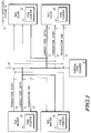
- FIG. 1 illustrates a data processing system 10 that includes one or more bus master devices 12-13 and one or more bus slave devices 14-15 which are bi-directionally coupled by way of bus 18.
- Central pipe counter 16 is also coupled to bus 18.
- Bus 18 includes a transaction start signal that is provided by bus masters 12-13 to bus slaves 14-15 and central pipe counter 16 by way of conductor 20. Bus 18 also includes a transaction end signal that is provided by one of bus slaves 14-15 to bus masters 12-13, to central pipe counter 16, and to the other of bus slaves 14-15 by way of conductor 22. And, bus 18 includes one or more current pipe depth signals 21 which are provided by central pipe counter 16 to bus master devices 12-13 and bus slave devices 14-15 by way of conductors 21. There are also other signals (not shown) which are included in bus 18, such as, for example, address signals, data signals, and various control signals.
- Bus master 12 includes a pipe counter 30 for keeping track of the pipe depth; and likewise, bus master 13 includes a pipe counter 31 for keeping track of the pipe depth.
- Bus slave 14 includes a pipe counter 32 for keeping track of the pipe depth; and likewise bus slave 15 includes a pipe counter 33 for keeping track of the pipe depth.
- all of data processing system 10 is integrated on a same integrated circuit. In alternate embodiments of the present invention, various portions of data processing system 10 may be integrated on different integrated circuits.
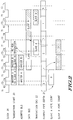
- FIG. 2 illustrates, in timing diagram form, a behavior of data processing system 10 of FIG. 1 in accordance with one embodiment of the present invention.
- clock signal 34 is an internal clock which is used only by bus master 12.
- clock signal 34 is included in bus 18 and is provided to all bus masters 12-13 and all bus slaves 14-15, as well as to central pipe counter 16.
- FIG. 3 illustrates a data processing system 40 that includes one or more bus master devices 42 and one or more bus slave devices 44 which are bi-directionally coupled by way of bus 48.
- bus master 42 is a central processing unit (CPU)
- bus slave 44 is a slave module
- central pipe counter 46 is a system integration unit (SIU).
- Information is communicated to and from data processing system 40 by way of external bus 80.
- all of data processing system 40 is integrated on a same integrated circuit, and SIU 46 is used to communicate external to the integrated circuit by way of external bus 80.
- various portions of data processing system 40 may be integrated on different integrated circuits.
- Bus 48 includes a transfer start signal that is provided by CPU 42 to slave 44 and SIU 46 by way of conductor 50, one or more current pipe depth signals 51 which are provided by SIU 46 to CPU 42 and slave 44 by way of conductors 51, a transfer acknowledge signal that is provided by slave 44 or SIU 46 to CPU 42 and to the other one of slave 44 and SIU 46 by way of conductor 52, a bus error signal that is provided by slave 44 or SIU 46 and is received by the other devices on bus 48 by way of conductor 53, an address recognized signal that is provided by slave 44 or SIU 46 to CPU 42 and SIU 46 by way of conductor 54, and an address acknowledge signal that is provided by slave 44 or SIU 46 to CPU 42 and SIU 46 by way of conductor 55.
- Bus 48 also includes an abort signal that is provided by CPU 42 to slave 44 and SIU 46 by way of conductor 56, a read /write signal that is provided by CPU 42 to slave 44 and SIU 46 by way of conductor 57, a plurality of address signals that are provided by CPU 42 to slave 44 and SIU 46 by way of conductors 58, a plurality of data signals that are either provided to CPU 42 from slave 44 or SIU 46 by way of conductors 58 or are provided from CPU 42 to slave 44 or SIU 46 by way of conductors 58, and finally, there are also other signals which are included in bus 18 (e.g. various control signals) that are transferred by way of conductors 60.
- abort signal that is provided by CPU 42 to slave 44 and SIU 46 by way of conductor 56
- a read /write signal that is provided by CPU 42 to slave 44 and SIU 46 by way of conductor 57
- a plurality of address signals that are provided by CPU 42 to slave 44 and SIU 46 by way of conductors
- CPU 42 includes control circuitry 70 which is bi-directionally coupled to counter 75.
- Slave 44 includes control circuitry 71 which is bi-directionally coupled to counter 76.
- SIU 46 includes control circuitry 72 which is bi-directionally coupled to counter 77.
- FIG. 4 illustrates, in tabular form, a behavior of data processing system 40 of FIG. 2 in accordance with one embodiment of the present invention.
- FIG. 5 illustrates, in flow diagram form, a behavior of data processing system 40 of FIG. 2 in accordance with one embodiment of the present invention.
- Ovals 90-91 indicate the initiation of a transaction to an address in slave 44 (see FIG. 3).
- Rectangles 92-94 indicate whether bus slave 44 has ownership of data bus 59.
- FIG. 6 illustrates, in timing diagram form, a behavior of data processing system 40 of FIG. 2 in accordance with one embodiment of the present invention.
- the present invention solves the problem of matching the initial address request by a bus master to the corresponding data response from a slave when the bus used for master-slave communication is a split-transaction bus and/or a pipelined bus.
- the present invention provides a method and apparatus for implementing a bus protocol which has in-order termination on the data bus.
- a central pipe counter 16 is used to track the current pipe depth (i.e. the number of pending transactions).
- the central pipe counter 16 is incremented each time that a new transaction is started (i.e. the transaction start signal 20 is asserted), and is decremented each time that a transaction is completed or terminated (i.e. the transaction end signal 22 is asserted).
- Each bus master 12-13 may initiate a new transaction only if the current pipe depth is less than a predetermined maximum pipe depth. For the embodiment of the present invention illustrated in FIG. 2, the maximum pipe depth is 2.
- the bus slave e.g. 14
- the bus slave receives and stores the current pipe depth value into pipe counter 32 from the current pipe depth signals 21.
- This bus slave 14 then decrements pipe counter 32 each time that a transaction is completed or terminated (i.e. each time that the transaction end signal 22 is asserted).
- the bus slave's pipe counter 32 is decremented to "0"
- the bus slave 14 knows that is will have ownership of the data bus during the next available data phase.
- bus master 12 Each time that a bus master (e.g. 12) initiates a transaction, bus master 12 must also track the pipe depth in the same manner as the recipient bus slave (e.g. 14) in order to know when the bus slave's data will be available on the data bus. Therefore, bus master 12, like bus slave 14, must store the current pipe depth value into its pipe counter 30 from the current pipe depth signals 21. Bus master 12 then decrements pipe counter 30 each time that a transaction is completed or terminated (i.e. each time that the transaction end signal 22 is asserted). When the bus master's pipe counter 30 is decremented to "0", the bus master 12 knows that is will be receiving data on the data bus from bus slave 14 during the next available data phase.
- Bus masters 12-13 must also monitor the current pipe depth signals 21 to determine if the current pipe depth is less than the predetermined maximum pipe depth. Bus masters 12-13 may not initiate a new transaction if the current pipe depth is at the maximum pipe depth (i.e. if the pipe is full). In some embodiments of the present invention, one or more of bus masters 12-13 may also have circuitry in their pipe counters 30-31 which allows the bus masters 12-13 to anticipate when the pipe depth will reach its maximum pipe depth. The advantage of this approach is that a bus master 12-13 may anticipate that the pipe is not yet full and may therefore initiate a new transaction even before the current pipe depth is available from the central pipe counter 16 on the current pipe depth signals 21. Note that the present invention does not requires any data bus arbitration or grant lines.
- data processing system 10 has a central pipe counter 16, one or more bus masters 12-13, and one or more bus slaves 14-15 which are all coupled to bus 18.
- FIG. 1 illustrates a set of basic control signals that may be included in bus 18 to implement the present invention. Alternate embodiments may use more, fewer, or different signals to implement the present invention.
- Bus 18 also includes an address bus (not shown separately) and a data bus (not shown separately).
- a bus master 12-13 initiates a new bus cycle by asserting the transaction start signal 20, and a bus slave 14-15 completes or ends that bus cycle by asserting the transaction end signal 22.
- Each bus cycle has a corresponding address phase and a corresponding data phase.
- each read bus cycle consists of an address phase in which the bus master 12-13 provides an address value to bus 18, followed by a data phase in which the bus slave 14-15 provides a corresponding data value to bus 18.
- Central pipe counter 16 keeps track of the number of pending accesses and provides current pipe depth signals 21 to the bus masters 12-13 and the bus slaves 14-15 in data processing system 10. In the embodiment of the present invention illustrated in FIG. 1, central pipe counter 16 is incremented every time that a transaction start occurs (i.e. every time that the transaction start signal 20 is asserted), and is decremented every time that a transaction end occurs (i.e. every time that the transaction end signal 22 is asserted).
- each bus slave 14-15 receives the transaction start signal 20 and the address value from bus master 12-13. Each bus slave 14-15 uses the received address value to determine whether the read bus cycle is attempting to access itself or another bus slave. If a bus slave 14-15 determines that the read bus cycle is not addressing it, it does not respond to the read bus cycle. If a bus slave 14-15 determines that the read bus cycle is addressing it, then bus slave 14-15 must respond by driving the data bus portion of bus 18 during the data phase that corresponds to this particular read bus cycle. Note that bus 18 also includes a read/write signal (not shown separately) which is provided by bus masters 12-13 to indicate to bus slaves 14-15 that the current bus cycle is a read access.
- a read/write signal (not shown separately) which is provided by bus masters 12-13 to indicate to bus slaves 14-15 that the current bus cycle is a read access.
- the key problem is how a particular bus slave 14-15 is able to determine which data phase "N" corresponds to the address phase "N" which accessed that particular slave. That is, if during bus cycle N, bus slave 14 receives one of its own address values on the address portion of bus 18, bus slave 14 must determine which time slot on the data portion of bus 18 corresponds to the bus cycle N. Then bus slave 14 must provide the data value to the data portion of bus 18 during the time slot on the data portion of bus 18 which corresponds to the bus cycle N.
- bus master 12 which initiated bus cycle N must also determine which time slot on the data portion of bus 18 corresponds to the bus cycle N so that bus master 12 can latch the return data provided by bus slave 14.
- bus master 12 stores a separate pipe depth value for each incomplete transaction which it initiated. This stored pipe depth value is decremented each time that the transaction end signal 22 is asserted. Thus, the same pipe depth value is captured from current pipe depth signals 21 and is stored in both the master's pipe counter 30 and in the slave's pipe counter 32. Both pipe counters 30 and 32 are decremented each time that the transaction end signal 22 is asserted. Note that for a pipe depth of 2, bus master 12 only needs to store one pipe depth value. The one or more stored pipe depth values may be stored in latches (not shown) in pipe counter 30. To complete bus cycle N, bus slave 14 must assert the transaction end signal 22.
- Pipe counter 32 may be an up-counter which is incremented until it reaches a predetermined match value or rolls over.
- Pipe counter 32 may be a down-counter which is loaded with the current pipe depth value and is decremented to a predetermined match value or zero.
- pipe counter 32 may be a state machine. The same is true for the implementation of the other pipe counters 30, 31, and 33.
- pipe counter 32 is a down-counter which is loaded with the current pipe depth value from signals 21 when an access to bus slave 14 is received. Bus slave 14 then decrements the counter value in pipe counter 32 every time that a transaction is completed (i.e. every time that the transaction end signal 22 is asserted). Thus, when the counter value in pipe counter 32 reaches zero, bus slave 14 determines that the next available data phase is for transaction N+1. So during the next available data phase, bus slave 14 drives its data value onto the data bus portion of bus 18.
- each bus master 12-13 and each bus slave 14-15 has a pipe counter 30-33 to determine when it has ownership of the data bus, while a central pipe counter 16 is used to keep track of the current pipe depth.
- FIG. 2 illustrates two pipelined transactions on bus 18 in FIG. 1.
- master-A (see FIG. 2) is bus master 12 (see FIG. 1)
- slave-A is bus slave 14
- master-B is bus master 13
- slave-B is bus slave 15.
- the first transaction is from bus master 12 to bus slave 14 (master-A to slave-A)
- the second transaction is from bus master 13 to bus slave 15 (master-B to slave-B).
- clock 34 is used to indicate timing relationships and is used by bus masters 12-13, bus slaves 14-15, and central pipe counter 16.
- each full period of clock 34 is divided into four equal time divisions or ticks which are sequentially labeled T1, T2, T3, and T4. Alternate embodiments of the present invention may use different timing relationships between the various signals on bus 18.
- Bus master 12 initiates the first transaction by asserting the transaction start signal 20 and driving the address bus portion of bus 18 with an address value for bus slave 14 on the first T3. As there have been no previous incomplete transactions, the current pipe depth value provided by central pipe counter 16 to signals 21 is zero.
- Each bus slave 14-15 responds to the assertion of the transaction start signal 20 by latching the address value and determining whether the address value is one of its own. Since the address value is for bus slave 14, bus slave 14 latches the current pipe depth value from signals 21 ("0" in this case) and stores this value in pipe counter 32. Note that bus master 12 also latches the current pipe depth value from signals 21 ("0" in this case) and stores this value in pipe counter 30.
- the "slave-A pipe count" value illustrated in FIG. 2 represents the value stored in pipe counter 32.
- bus slave 15 Since the address value is not for bus slave 15, bus slave 15 does not latch the current pipe depth value from signals 21 and no value is stored in pipe counter 33.
- the "slave-B pipe count" value illustrated in FIG. 2 represents the value stored in pipe counter 33. Note that in response to the assertion of the transaction start signal 20, the central pipe counter 16 increments its counter and drives the current pipe depth signals 21 with the new current pipe depth value (namely "1").
- bus slave 14 determines that the next data phase belongs to bus slave 14. Thus, bus slave 14 drives the data bus with its response data value during the next available time slot of the data bus. As the counter value stored in pipe counter 30 is "0", bus master 12 determines that bus slave 14 is responding with its data value during the next available time slot of the data bus.
- Bus master 13 initiates the second transaction by asserting the transaction start signal 20 and driving the address bus portion of bus 18 with an address value for bus slave 15 on the second T3. As there is one previous incomplete transaction, the current pipe depth value provided by central pipe counter 16 to signals 21 is "1".
- Each bus slave 14-15 responds to the assertion of the transaction start signal 20 by latching the address value and determining whether the address value is one of its own. Since the address value is for bus slave 15, bus slave 15 latches the current pipe depth value from signals 21 ("1" in this case) and stores this value in pipe counter 33. Likewise, bus master 13 latches the current pipe depth value from signals 21 ("1" in this case) and stores this value in pipe counter 31. Since the address value is not for bus slave 14, bus slave 14 does not latch the current pipe depth value from signals 21 and no new value is stored in pipe counter 32; pipe counter 32 still contains a "0". Note that in response to the second assertion of the transaction start signal 20, the central pipe counter 16 increments its counter and drives the current pipe depth signals 21 with the new current pipe depth value (namely "2").
- bus slave 15 determines that the next data phase does not belong to bus slave 15. Thus, bus slave 15 waits and does not drive the data bus with its response data value. As the counter value stored in pipe counter 31 is "1", bus master 13 determines that bus slave 15 is not responding with its data value during the next available time slot of the data bus.
- bus slave 14 When bus slave 14 completes the data phase for the first transaction, bus slave 14 asserts the transaction end signal 22.
- Bus slave 15 and bus master 13 respond to the assertion of the transaction end signal 22 by decrementing the value stored in their respective pipe counters 31 and 33.
- central pipe counter 16 responds to the assertion of the transaction end signal 22 by decrementing its counter and driving the current pipe depth signals 21 with the new current pipe depth value (namely "1").
- bus slave 15 determines that the next data phase belongs to bus slave 15. Thus, bus slave 15 drives the data bus with its response data value during the next available time slot of the data bus. As the counter value stored in pipe counter 31 is "0", bus master 13 determines that bus slave 15 is responding with its data value during the next available time slot of the data bus.
- bus slave 15 When bus slave 15 completes the data phase for the second transaction, bus slave 15 asserts the transaction end signal 22.
- Central pipe counter 16 responds to the assertion of the transaction end signal 22 by decrementing its counter and driving the current pipe depth signals 21 with the new current pipe depth value (namely "0").
- FIGS. 1 and 2 illustrate a pipe depth of 2
- alternate embodiments of the present invention may use any pipe depth.
- the number of current pipe depth signals 21, the number of bits and latches in pipe counters 30-33, and the number of bits in central pipe counter 16 may be scaled to accommodate any pipe depth.
- bus masters 12-13 can use the current pipe depth signals 21 to determine whether or not the maximum pipe depth has been reached, and thus whether or not a new transaction can be started. If the maximum pipe depth has been reached, bus masters 12-13 refrain from initiating a new transaction. If bus masters 12-13 determine from the current pipe depth signals 21 that the maximum pipe depth has been reached, bus masters 12-13 continue to monitor the current pipe depth signals 21 until the central pipe counter 16 decrements the current pipe depth value in response to receiving an asserted transaction end signal 22 from one of the bus slaves 14-15. Once the current pipe depth signals 21 indicate that the pipe depth is no longer at its maximum value, bus masters 12-13 may initiate a new transaction on bus 18.
- FIG. 3 illustrates an alternate embodiment of the present invention.
- the transfer start signal 50 illustrated in FIG. 3 serves the same general purpose as the transaction start signal illustrated in FIG. 1; both signals are asserted by a bus master in order to initiate the address phase of a new transaction.
- the transfer acknowledge signal 52 illustrated in FIG. 3 serves the same general purpose as the transaction end signal illustrated in FIG. 1; both signals are asserted by a bus slave in order to indicate the completion of the data phase of a transaction.
- the current pipe depth signals 51 illustrated in FIG. 3 serves the same general purpose as the current pipe depth signals illustrated in FIG. 1; both broadcast the current pipe depth to bus master and bus slaves.
- the SIU 46 functions as both the central pipe counter and as a bus slave. Alternate embodiments may have the central pipe counter 46 separate from all of the bus slaves. Also, in alternate embodiments of the present invention, instead of having one central pipe counter 46, each bus master (e.g. 42) may keep track of the current pipe depth and may provide the current pipe depth signals 51 for each transaction which that bus master initiates.
- a bus slave 44 may indicate the completion of the data phase of a transaction by either asserting the transfer acknowledge signal 52 if the transaction has competed without error, or by asserting the bus error signal 53 if the transaction has competed with a bus error.
- bus master 42, bus slave 44, and central pipe counter 46 must monitor both the transfer acknowledge signal 52 and the bus error signal 53 in order to properly decrement their respective counters 75-77.
- Alternate embodiments of the present invention may use any combination of one or more signals to indicate the completion of the data phase of a transaction, as long as the counters 75-76 can be selectively adjusted (i.e. incremented or decremented) based on the one or more signals which indicate that the data phase of a transaction has completed.
- counters 75-76 may also be implemented as state machines.
- the address recognized signal 54 and the address acknowledge signal 55 are provided by bus slave 14 to indicate the completion of the address phase of a transaction.
- the abort signal 56 is provided by bus master 42 in order to abort an address phase of a transaction.
- bus master 42, bus slave 44, and central pipe counter 46 must monitor both the transfer start signal 50 and the abort signal 56 in order to properly increment their respective counters 75-77.
- Alternate embodiments of the present invention may use any combination of one or more signals to indicate that a transaction has been started and will not be aborted before a corresponding data phase is completed.
- address bus 58, the data bus 59, and the read/write signal 57 are expressly illustrated.
- address bus 58 and data bus 59 are pipelined, split transaction buses.
- Bus 48 also includes other signals 60 which may be used for control or for transferring information, such as, for example, address attribute information (e.g. supervisor/user space).
- FIG. 4 indicates how the pipe depth value in counter 77 is incremented and decremented in one embodiment of the present invention.
- the column titled "previous pipe depth” indicates the present value stored in counter 77 (see FIG. 3).
- the column titled “next pipe depth” indicates the next value to be stored in counter 77, as determined by various signals on bus 48.
- the next pipe depth is a function of the transfer start signal 50, the address acknowledge signal 55, the abort signal 56, and the transfer acknowledge signal 52.
- next pipe depth is also a function of the bus error signal 53 which may be used in the same manner as the transfer acknowledge signal 52 to indicate the completion of the data phase of a transaction. Alternate embodiments of the present invention may not use a bus error signal 53, or may not use the bus error signal 53 in this manner.
- the column titled "start a new cycle on T3?" indicates whether or not the maximum pipe depth has been reached, and thus whether a bus master 42 can initiate a new transaction or bus cycle on bus 48. Since the maximum pipe depth for the data processing system 40 illustrated in FIG. 3 is 2, bus master 42 does not initiate a new transaction when the next pipe depth value will be "2".
- control circuitry 70 in bus master 42 may duplicate most or all of the control circuitry 72 in the central pipe counter 46 so that bus master 42 may effectively anticipate when the maximum pipe depth will be reached.
- bus master 42 may effectively anticipate when the maximum pipe depth will be reached by calculating the next pipe value in the same manner as central pipe counter 46 (see table in FIG. 4).
- bus master 42 has a more simple counter 75 and must wait for the next pipe depth value to be provided from central pipe counter 46 by way of the current pipe depth signals 51.
- FIG. 5 illustrates a flow diagram of the behavior of bus slave 44, assuming that bus slave 44 is available to respond to the transaction and the transaction is not aborted.
- bus slave 44 will wait for the data bus 59 to be granted before responding (see rectangle 92).
- counter 76 stores the least significant bit of the current pipe depth signals 51. Thus, counter 76 stores a "1”.
- the transfer acknowledge signal 52 is asserted, counter 76 is decremented so that it now contains "0”, thus indicating that the data bus 59 has been granted and bus slave 44 may respond by driving the data bus 59 with the appropriate data value (see rectangle 93).
- the transfer acknowledge signal 52 is then asserted by bus slave 44, counter 76 is not affected (it continues to store a "0"), and the data bus 59 is now idle as no other transactions are pending (see rectangle 94).
- bus slave 44 determines that data bus 59 has been granted, and bus slave 44 responds by driving the data bus 59 with the appropriate data value (see rectangle 93).
- the transfer acknowledge signal 52 is then asserted by bus slave 44, counter 76 is not affected (it continues to store a "0"), and the data bus 59 is now idle as no other transactions are pending (see rectangle 94).
- FIG. 6 illustrates three pipelined transactions on bus 48 (see FIG. 3).
- the first transaction is a read access to a first bus slave (e.g. bus slave 14)
- the second transaction is a write access to a second bus slave
- the third transaction is a read access to a third bus slave.
- clock 64 is used to indicate timing relationships and is used by bus master 12, bus slave 14, and central pipe counter 46.
- each full period of clock 34 is divided into four equal time divisions or ticks which are sequentially labeled T1, T2, T3, and T4. Alternate embodiments of the present invention may use different timing relationships between the various signals on bus 48.
- any type of address bus arbitration for ownership of address signals 58 may be used.
- the bus master 42 drives the data bus 59 with the data value during T4
- the bus slave 44 drives the data bus 59 with the data value during T2.
- data bus 59 is an in-order termination bus
- each bus slave must keep track of whether it has ownership of data bus 59 so that it may properly terminate the data phase of a transaction by asserting the transfer acknowledge signal 52 at the proper time.
- the second slave is being accesses for a write access and latches the data value from data bus 59 during T4, the second slave must latch the current pipe depth value from signals 51 in order to determine when it should assert the transfer acknowledge signal 52.
- the incrementing and decrementing of counters 75-77 can be qualified by the read/write signal so that counters 75-77 ignore all write access and data bus ownership during read accesses is determined independent of all write accesses.
- the data bus ownership during write accesses is given to the bus master that initiated the most recent transaction, and write accesses on the data bus uses time slots that do not conflict with read accesses on the data bus (e.g. write accesses use time slots T3 and T4 of the data bus, while read access use time slots T1 and T2 of the data bus).
- FIGS. 3-6 illustrate a pipe depth of 2
- alternate embodiments of the present invention may use any pipe depth.
- the number of current pipe depth signals 51 and the number of bits and latches in counters 75-77 may be scaled to accommodate any pipe depth.
Landscapes
- Engineering & Computer Science (AREA)
- Theoretical Computer Science (AREA)
- General Engineering & Computer Science (AREA)
- Physics & Mathematics (AREA)
- General Physics & Mathematics (AREA)
- Computer Hardware Design (AREA)
- Bus Control (AREA)
- Information Transfer Systems (AREA)
Applications Claiming Priority (2)
| Application Number | Priority Date | Filing Date | Title |
|---|---|---|---|
| US08/363,435 US5699516A (en) | 1994-12-22 | 1994-12-22 | Method and apparatus for implementing a in-order termination bus protocol within a data processing system |
| US363435 | 1994-12-22 |
Publications (1)
| Publication Number | Publication Date |
|---|---|
| EP0720099A1 true EP0720099A1 (de) | 1996-07-03 |
Family
ID=23430202
Family Applications (1)
| Application Number | Title | Priority Date | Filing Date |
|---|---|---|---|
| EP95119620A Ceased EP0720099A1 (de) | 1994-12-22 | 1995-12-13 | Verfahren und Vorrichtung zur Durchführung eines Busprotokolls mit geordnetem Betrieb |
Country Status (4)
| Country | Link |
|---|---|
| US (1) | US5699516A (de) |
| EP (1) | EP0720099A1 (de) |
| JP (1) | JP4040704B2 (de) |
| KR (1) | KR100354934B1 (de) |
Cited By (3)
| Publication number | Priority date | Publication date | Assignee | Title |
|---|---|---|---|---|
| US6948019B2 (en) * | 2002-04-30 | 2005-09-20 | Lsi Logic Corporation | Apparatus for arbitrating non-queued split master devices on a data bus |
| US7174401B2 (en) | 2002-02-28 | 2007-02-06 | Lsi Logic Corporation | Look ahead split release for a data bus |
| WO2008056205A1 (en) * | 2006-11-08 | 2008-05-15 | Freescale Semiconductor, Inc. | Device and method for managing access requests |
Families Citing this family (22)
| Publication number | Priority date | Publication date | Assignee | Title |
|---|---|---|---|---|
| US5615343A (en) * | 1993-06-30 | 1997-03-25 | Intel Corporation | Method and apparatus for performing deferred transactions |
| US5809258A (en) * | 1994-08-23 | 1998-09-15 | Ascom Timeplex Trading Ag | Bus with high gross data transfer rate |
| US6085261A (en) * | 1996-07-29 | 2000-07-04 | Motorola, Inc. | Method and apparatus for burst protocol in a data processing system |
| US5881224A (en) * | 1996-09-10 | 1999-03-09 | Hewlett-Packard Company | Apparatus and method for tracking events in a microprocessor that can retire more than one instruction during a clock cycle |
| US5887003A (en) * | 1996-09-10 | 1999-03-23 | Hewlett-Packard Company | Apparatus and method for comparing a group of binary fields with an expected pattern to generate match results |
| US6003107A (en) * | 1996-09-10 | 1999-12-14 | Hewlett-Packard Company | Circuitry for providing external access to signals that are internal to an integrated circuit chip package |
| US5867644A (en) * | 1996-09-10 | 1999-02-02 | Hewlett Packard Company | System and method for on-chip debug support and performance monitoring in a microprocessor |
| US5880671A (en) * | 1996-10-31 | 1999-03-09 | Hewlett-Packard Company | Flexible circuitry and method for detecting signal patterns on a bus |
| US5956476A (en) * | 1996-10-31 | 1999-09-21 | Hewlett Packard Company | Circuitry and method for detecting signal patterns on a bus using dynamically changing expected patterns |
| US5956477A (en) * | 1996-11-25 | 1999-09-21 | Hewlett-Packard Company | Method for processing information in a microprocessor to facilitate debug and performance monitoring |
| US5881217A (en) * | 1996-11-27 | 1999-03-09 | Hewlett-Packard Company | Input comparison circuitry and method for a programmable state machine |
| US6009539A (en) * | 1996-11-27 | 1999-12-28 | Hewlett-Packard Company | Cross-triggering CPUs for enhanced test operations in a multi-CPU computer system |
| KR100414750B1 (ko) * | 1997-06-20 | 2005-09-28 | 주식회사 하이닉스반도체 | 동기식 그래픽 램에서의 파이프 카운터 제어회로 |
| US6240479B1 (en) | 1998-07-31 | 2001-05-29 | Motorola, Inc. | Method and apparatus for transferring data on a split bus in a data processing system |
| US6374370B1 (en) | 1998-10-30 | 2002-04-16 | Hewlett-Packard Company | Method and system for flexible control of BIST registers based upon on-chip events |
| US6813251B1 (en) * | 1999-07-27 | 2004-11-02 | Intel Corporation | Split Transaction protocol for a bus system |
| US6772254B2 (en) | 2000-06-21 | 2004-08-03 | International Business Machines Corporation | Multi-master computer system with overlapped read and write operations and scalable address pipelining |
| US6970962B2 (en) * | 2003-05-19 | 2005-11-29 | International Business Machines Corporation | Transfer request pipeline throttling |
| US7711909B1 (en) * | 2004-12-09 | 2010-05-04 | Oracle America, Inc. | Read sharing using global conflict indication and semi-transparent reading in a transactional memory space |
| JP2007122410A (ja) * | 2005-10-28 | 2007-05-17 | Nec Electronics Corp | バス調停回路及びバス調停方法 |
| US8185680B2 (en) * | 2006-02-06 | 2012-05-22 | Standard Microsystems Corporation | Method for changing ownership of a bus between master/slave devices |
| US9213665B2 (en) * | 2008-10-28 | 2015-12-15 | Freescale Semiconductor, Inc. | Data processor for processing a decorated storage notify |
Citations (2)
| Publication number | Priority date | Publication date | Assignee | Title |
|---|---|---|---|---|
| FR2637997A1 (fr) * | 1988-10-14 | 1990-04-20 | Intel Corp | Procede et dispositif pour mettre en file d'attente des requetes et des reponses sur un bus |
| US5345562A (en) * | 1992-02-12 | 1994-09-06 | Industrial Technology Research Institute | Data bus arbitration for split transaction computer bus |
Family Cites Families (6)
| Publication number | Priority date | Publication date | Assignee | Title |
|---|---|---|---|---|
| US5345578A (en) * | 1989-06-30 | 1994-09-06 | Digital Equipment Corporation | Competitive snoopy caching for large-scale multiprocessors |
| IL96808A (en) * | 1990-04-18 | 1996-03-31 | Rambus Inc | Introductory / Origin Circuit Agreed Using High-Performance Brokerage |
| US5191649A (en) * | 1990-12-21 | 1993-03-02 | Intel Corporation | Multiprocessor computer system with data bus and ordered and out-of-order split data transactions |
| US5255373A (en) * | 1991-08-07 | 1993-10-19 | Hewlett-Packard Company | Decreasing average time to access a computer bus by eliminating arbitration delay when the bus is idle |
| US5588125A (en) * | 1993-10-20 | 1996-12-24 | Ast Research, Inc. | Method and apparatus for increasing bus bandwidth on a system bus by inhibiting interrupts while posted I/O write operations are pending |
| US5546546A (en) * | 1994-05-20 | 1996-08-13 | Intel Corporation | Method and apparatus for maintaining transaction ordering and arbitrating in a bus bridge |
-
1994
- 1994-12-22 US US08/363,435 patent/US5699516A/en not_active Expired - Fee Related
-
1995
- 1995-12-13 EP EP95119620A patent/EP0720099A1/de not_active Ceased
- 1995-12-15 JP JP34769495A patent/JP4040704B2/ja not_active Expired - Fee Related
- 1995-12-19 KR KR1019950051785A patent/KR100354934B1/ko not_active Expired - Fee Related
Patent Citations (2)
| Publication number | Priority date | Publication date | Assignee | Title |
|---|---|---|---|---|
| FR2637997A1 (fr) * | 1988-10-14 | 1990-04-20 | Intel Corp | Procede et dispositif pour mettre en file d'attente des requetes et des reponses sur un bus |
| US5345562A (en) * | 1992-02-12 | 1994-09-06 | Industrial Technology Research Institute | Data bus arbitration for split transaction computer bus |
Cited By (4)
| Publication number | Priority date | Publication date | Assignee | Title |
|---|---|---|---|---|
| US7174401B2 (en) | 2002-02-28 | 2007-02-06 | Lsi Logic Corporation | Look ahead split release for a data bus |
| US6948019B2 (en) * | 2002-04-30 | 2005-09-20 | Lsi Logic Corporation | Apparatus for arbitrating non-queued split master devices on a data bus |
| WO2008056205A1 (en) * | 2006-11-08 | 2008-05-15 | Freescale Semiconductor, Inc. | Device and method for managing access requests |
| US8006015B2 (en) * | 2006-11-08 | 2011-08-23 | Freescale Semiconductor, Inc. | Device and method for managing access requests |
Also Published As
| Publication number | Publication date |
|---|---|
| JPH08255124A (ja) | 1996-10-01 |
| US5699516A (en) | 1997-12-16 |
| JP4040704B2 (ja) | 2008-01-30 |
| KR100354934B1 (ko) | 2003-01-29 |
| KR960025090A (ko) | 1996-07-20 |
Similar Documents
| Publication | Publication Date | Title |
|---|---|---|
| US5699516A (en) | Method and apparatus for implementing a in-order termination bus protocol within a data processing system | |
| US6173349B1 (en) | Shared bus system with transaction and destination ID | |
| US5535341A (en) | Apparatus and method for determining the status of data buffers in a bridge between two buses during a flush operation | |
| US5274763A (en) | Data path apparatus for IO adapter | |
| US5253348A (en) | Method of arbitration for buses operating at different speeds | |
| US6094700A (en) | Serial bus system for sending multiple frames of unique data | |
| US5901295A (en) | Address and data bus arbiter for pipelined transactions on a split bus | |
| US5047921A (en) | Asynchronous microprocessor random access memory arbitration controller | |
| US5313591A (en) | Computer bus arbitration for N processors requiring only N unidirectional signal leads | |
| JP2822986B2 (ja) | Dma内蔵シングルチップマイクロコンピュータ | |
| US6598104B1 (en) | Smart retry system that reduces wasted bus transactions associated with master retries | |
| KR930002787B1 (ko) | 주변 제어기와 어댑터 인터페이스 | |
| US4622630A (en) | Data processing system having unique bus control protocol | |
| JP2501737B2 (ja) | デ―タ転送方法及び装置 | |
| US5640517A (en) | Method and apparatus for masters to command a slave whether to transfer data in a sequential or non-sequential burst order | |
| KR100395383B1 (ko) | 데이터 전송 장치 | |
| US6175887B1 (en) | Deterministic arbitration of a serial bus using arbitration addresses | |
| US5255373A (en) | Decreasing average time to access a computer bus by eliminating arbitration delay when the bus is idle | |
| US6115767A (en) | Apparatus and method of partially transferring data through bus and bus master control device | |
| US5717931A (en) | Method and apparatus for communicating between master and slave electronic devices where the slave device may be hazardous | |
| US5708783A (en) | Data bus arbiter for pipelined transactions on a split bus | |
| US5526494A (en) | Bus controller | |
| US5671370A (en) | Alternating data valid control signals for high performance data transfer | |
| JPH051504B2 (de) | ||
| KR100243868B1 (ko) | 주 전산기에서의 중재로직 방법 |
Legal Events
| Date | Code | Title | Description |
|---|---|---|---|
| PUAI | Public reference made under article 153(3) epc to a published international application that has entered the european phase |
Free format text: ORIGINAL CODE: 0009012 |
|
| AK | Designated contracting states |
Kind code of ref document: A1 Designated state(s): DE FR GB NL |
|
| 17P | Request for examination filed |
Effective date: 19970103 |
|
| 17Q | First examination report despatched |
Effective date: 19980226 |
|
| GRAG | Despatch of communication of intention to grant |
Free format text: ORIGINAL CODE: EPIDOS AGRA |
|
| STAA | Information on the status of an ep patent application or granted ep patent |
Free format text: STATUS: THE APPLICATION HAS BEEN REFUSED |
|
| 18R | Application refused |
Effective date: 19990607 |