EP0720125B1 - Dispositif de formation d'image et procédé pour effectuer des corrections de distorsions optiques géométriques dans une image - Google Patents
Dispositif de formation d'image et procédé pour effectuer des corrections de distorsions optiques géométriques dans une image Download PDFInfo
- Publication number
- EP0720125B1 EP0720125B1 EP95203550A EP95203550A EP0720125B1 EP 0720125 B1 EP0720125 B1 EP 0720125B1 EP 95203550 A EP95203550 A EP 95203550A EP 95203550 A EP95203550 A EP 95203550A EP 0720125 B1 EP0720125 B1 EP 0720125B1
- Authority
- EP
- European Patent Office
- Prior art keywords
- grating
- image
- centre
- points
- grid
- Prior art date
- Legal status (The legal status is an assumption and is not a legal conclusion. Google has not performed a legal analysis and makes no representation as to the accuracy of the status listed.)
- Expired - Lifetime
Links
Images






Classifications
-
- G—PHYSICS
- G06—COMPUTING OR CALCULATING; COUNTING
- G06T—IMAGE DATA PROCESSING OR GENERATION, IN GENERAL
- G06T5/00—Image enhancement or restoration
- G06T5/80—Geometric correction
-
- H—ELECTRICITY
- H04—ELECTRIC COMMUNICATION TECHNIQUE
- H04N—PICTORIAL COMMUNICATION, e.g. TELEVISION
- H04N23/00—Cameras or camera modules comprising electronic image sensors; Control thereof
- H04N23/80—Camera processing pipelines; Components thereof
- H04N23/81—Camera processing pipelines; Components thereof for suppressing or minimising disturbance in the image signal generation
-
- H—ELECTRICITY
- H04—ELECTRIC COMMUNICATION TECHNIQUE
- H04N—PICTORIAL COMMUNICATION, e.g. TELEVISION
- H04N25/00—Circuitry of solid-state image sensors [SSIS]; Control thereof
- H04N25/60—Noise processing, e.g. detecting, correcting, reducing or removing noise
- H04N25/61—Noise processing, e.g. detecting, correcting, reducing or removing noise the noise originating only from the lens unit, e.g. flare, shading, vignetting or "cos4"
Definitions
- the invention relates to an image forming device comprising: a system for shooting, a system for capturing data from a source image distorted by the system of shooting, a system for digitizing said source image including a first image memory for storing the intensity data of each pixel identified by a address in a two-dimensional matrix, a digital image processing system construction of a target image corrected in distortions, corresponding to the source image.
- the invention also relates to a method for carrying out corrections of geometric optical distortions produced by a camera in a picture.
- the invention finds its application in the correction of the images scanned in the field of R-X systems, or video systems, or imaging systems digital.
- This device includes a recording camera of the image formed by the optical system, and means for digitizing this image which include the storage of intensity data for each current pixel.
- This device includes in addition an error corrector to compensate for geometric, recording errors, and chromatic and thus compensate for the optical imperfections of the shooting system at lens.
- This error corrector is controlled by a correction controller.
- This controller of correction receives, via an interface, external information, appropriate to the program it to supply the error corrector with control signals which take taking into account the parameters of the shooting system. Under these conditions, the corrector is able to correct the pixel data.
- a map memory receives these control signals from the correction controller depending on the settings of the shooting system. This map memory is tabulated according to these parameters so as to define the mapping that it is necessary to use to correct faults of the optical system with a type of lens given and under given shooting conditions. Memory output is provided to an interpolator used to improve the definition of the image of exit. Map memory is calibrated by providing the shooting camera a test pattern with a regular square grid pattern, and manually adjusting the stored parameters, so as to obtain a corrected grid at the output of the device. This operation can be carried out by displaying for example the output of the device on a screen fitted with a superimposed graticule.
- the device known from patent GB 2 256 989 does not therefore correct the imperfections of the shooting system automatically. You have to provide him with lens focal length, shooting distance, and zoom ratio data used. It is also necessary to enter a cartographic memory, for each type of lens and each shooting condition, tables from which the information on the new addresses to assign to the pixels of the target image, to replace the original addresses of these pixels in the source image, i.e. in the image straight from the shooting system and tainted with imperfections. So the target image can be corrected for distortions in the source image. No automatic means of tabulation of the cartographic memory, or automatic means to calculate correction functions to be applied to the pixels of the source image, to obtain the pixels of the target image is only taught by the cited document. Only means of calibration map memory manuals are disclosed, including image overlay target distorted from a grid on a reference graticule and correction by manual action on input parameters of the shooting system.
- An object of the present invention is to provide a device, as well as a method, to calculate optical distortion correction functions of a pickup system view, to obtain pixel data for constructing a corrected target image.
- a method for correcting optical distortions produced by a shooting system, in one image, includes steps as claimed in the Claim 2.
- a camera shooting system can include a wide angle lens optical system, or a zoom lens system which produce geometric optical distortions in the image formed by this camera. These distortions appear even if the optical system is of very good quality.
- an image forming device includes a shooting system 1 having an optical lens system, which provides an image distorted by a scene.
- This optical system 1 with lens is attached to a camera 2 which converts the optical image into electrical signals using a CCD element for example.
- These electrical signals are supplied to a digitization system 3 capable of storing the digitized image data, i.e. intensity data for each address pixels of the image identified in a two-dimensional matrix, in a first image memory.
- This scanned image data relates to the distorted image.
- This image forming device also includes a system for processing digital signal which comprises a subset 47 which processes the image data scanned stored in the image memory of scanning system 3 to provide data of a corresponding digital image, reconstructed with correction of distortions, this data being finally stored in a second image memory.
- a system for processing digital signal which comprises a subset 47 which processes the image data scanned stored in the image memory of scanning system 3 to provide data of a corresponding digital image, reconstructed with correction of distortions, this data being finally stored in a second image memory.
- the source image SI will be called the digital image data output from the scanning system 3 relating to an image distorted by the shooting system, and target image TI the digital image data supplied by the subset 47 of the image processing system, relating to the reconstructed image corrected in distortion.
- the sub-assembly 47 of the image processing system comprises, stored in a chip or in a table (LOOK UP TABLE) of the laws of correction of the distortions for build the corrected target image TI. These laws must be determined by means of a process comprising preliminary steps.
- One of the objects of the invention is to provide such a process for determining these correction laws automatically.
- the laws of corrections are determined once and for all in a first subset 4 of the processing system. Then they are applied automatically by means of the subset 47 of the image processing system called second sub-assembly 47.
- the INT switch in FIG.1A makes it possible to switch off the first sub-assembly 4 of the processing system, when these laws have been determined.
- This first sub-assembly 4 could also be an extension of the digitization system 3, or be integrated in this scanning system 3.
- FIG.2 represents the different stages by a schematic block diagram.
- This process does not require any preliminary measurements such as measuring the focal length, or the measurement of the shooting distance, or the actual measurement of the pitch of a test grid.
- This method is based on the use of the assumption that the geometric distortions generated by the shooting system are radial, that is to say that, in the target image constructed by the second subset 47 of the system of processing, a corrected point must be on a radius determined by the distorted point and by the center of distortion. This is why this method requires, in addition to the determination of the correction laws, the concomitant precise determination of the distortion center. However, this process does not require any real precise preliminary measurement. In this process, we will not seek to measure precisely, by a sensor for example, the location of the optical center of the camera, since only the center of distortion of the source image is interesting, because the distortions are radial around the center of distortion.
- this method implemented in the first subset 4 includes at least the following steps:
- This step includes the following substeps.
- a test pattern M is produced.
- it is preferably chosen to carry out the drawing of a grid on a rigid flat support.
- the meshes of this grid can be square or rectangular.
- this target can be a drawing on a support at bottom 1m x 1.50m white, representing horizontal black bars and vertical forming square meshes as shown in M in FIG.1A.
- the calibration conditions therefore essentially consist in verifying three conditions of orthogonality, two of these conditions of orthogonality being satisfied when the optical axis X'X of the camera is perpendicular to the plane of the target, and the third when the bars of the target grid are parallel respectively to the orthogonal lines and columns of the CCD element of the camera.
- the calibration operation can be carried out by simply using brackets. This calibration is not binding because it appears that the method according to the invention is very robust to possible imperfections of this calibration.
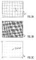
- the digitization system 3 provides a digitized image thereof in the form of a 'a grid, called source grid SG -2 , showing optical distortions as shown in FIG.3A.
- Distortions can be cushion-shaped like in FIG.5A, or shaped barrels as in FIGs 5B and 3A.
- An image of the distorted source grid is digitized and stored in the media scanning and storage 3 shown in FIG. 1.
- the areas of intersection of the vertical bars and the horizontal bars are black as shown in FIG.3A.
- the digitized image of the distorted grid SG -2 is processed to make these areas clear, and to make the rest of the image darker. We then obtain the image of a source grid noted SG -1 as shown next in FIG. 3B.
- This treatment can be carried out by a first method known to man of the trade consisting of a linear filtering by means of linear filters corresponding to correlation masks in the shape of a cross.
- the enhancement of the intensities of the intersections of the grid bars is essential. It is therefore important to carry out very good filtering.
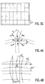
- FIG.4A An intersection of a horizontal grid bar with a vertical grid bar is shown schematically in FIG.4A.
- the edges of the horizontal bar and the vertical bars are represented by distorted lines since we are in the distorted source image.
- the distance d1 is chosen such that the selected cardinal points are located at inside the grid bars design when center C is located in the area intersection. This result is obtained by choosing d1 on the order of 1 to 5 pixels; generally around half the thickness of a grid bar measured in pixels in the distorted image.
- the distance d2 is chosen so that the corresponding diagonal points are located in the background of the image, i.e. outside the bar drawing regions grid. This effect is obtained by choosing d2 measured in pixels, of the order of half the not the distorted grid in the scanned image. For example for a grid with a pitch of the order of 50 pixels, d2 could be 20 pixels.
- this filtering allows to obtain that, when the center of the filter is inside an intersection zone, then the cardinal points S, N, E, W are inside the regions of the bar drawings grid, and the diagonal points are actually in the background, and this even in the regions of the distorted image where the greatest distortions are found.
- FILT Min (NW, NE, SE, SW) -Max (C, N, S, E, W).
- Min (NW, NE, SW, SE) means that we evaluate the minimum intensity relative to the points diagonally
- Max (C, N, S, E, W) means that we evaluate the maximum intensity relative to the cardinal points including the center.
- the non-linear filter performs the evaluation of this FILT criterion at each point of the image distorted from FIG. 3A.
- the result of the calculation of the FILT criterion constitutes the output of the filter not linear according to the invention.
- the regions of intersection detected are those where the measurement of this criterion is the greatest.
- the image obtained resulting from this filtering is a new source grid SG -1 and shows, as in FIG. 3B, that the regions of intersection are enhanced in intensity, and that the other regions of the distorted source image are darkened .
- a thresholding sub-step is carried out on the intensity of these points.
- a thresholding is carried out in the enhanced image SG -1 by selecting a number referenced Nb representing the number of points of higher intensity.
- a histogram is produced by counting, for each level intensity, the number of pixels having this intensity.
- the thresholding operation consists in summing the number of pixels by intensity level decreasing, and to stop the summation when the number Nb threshold is reached. So the pixels of higher intensity are retained and their address and intensity data are stored.
- the image produced from the test grid is only formed of bright areas containing a certain number of pixels whose intensity is greater than or equal to the intensity corresponding to the threshold Nb on the histogram, the background being uniformly dark and devoid of the details of bars that were still visible after filtering on the image SG -1 of FIG.3B.
- the pixels extracted by thresholding in the previous step are grouped by a labeling method.
- the intersection zones each containing a few thresholded pixels grouped are identified, then their barycenter is calculated.
- the barycenters thus extracted constitute points hereinafter called reference points R k , where k is the number which makes it possible to number each of the reference points in the source image SG 0 thus obtained.
- Each R k corresponds to an address in the source image SG 0 now obtained, given by the coordinates of the calculated barycenter. These coordinates are denoted rx k along the x axis and ry k along the y axis of a fixed coordinate reference ⁇ x, ⁇ y used in this source image SG 0 .
- This coordinate system is orthogonal and its axes coincide respectively with a line and a column of pixels in this image.
- the barycentres or reference points R k extracted are represented by black dots on a white background for the convenience of the drawing, while in the example described, they are in reality white on a black background.
- the method of the invention now comprises steps for constructing a target image of a grid called theoretical grid TG n which represents the grid SG 0 of the source image (FIG.3C) corrected for its geometric distortions.
- the method according to the invention provides transformation functions, making it possible to construct this corrected theoretical grid TG n very precisely, from image data of the source grid SG 0 ; these image data are initially constituted by the coordinates rx k , ry k of the reference points R k in the frame ⁇ x, ⁇ y.
- the corrected theoretical grid TG n is constructed based on the assumption that the source image is radially distorted around a center of distortion with respect to the target image to be constructed.
- the reference points R k the source image are represented by small circles, and the points of intersection TR 0 / m of the theoretical grid by small crosses in black on a white background, whatever their actual intensity level for the simplification of the drawings.
- This first theoretical grid is entirely defined as soon as a center GC 0 and a step GM 0 are determined.
- the bars of the theoretical grid are orthogonal and regularly spaced. It should be noted that this center of the theoretical grid can be found anywhere in the image, and even, possibly outside the image.
- the estimation of a center GC 0 for the first theoretical grid is carried out around the center of distortion of the distorted source grid, to lead to an easy estimation of the pitch GM 0 of this first theoretical grid TG 0 .
- any function capable of providing the estimate of a reference point, denoted R 0 / k, closest to the center of distortion of the source grid SG 0 can be used.
- R 0 / k the estimate of a reference point
- This approximate source grid pitch is defined for two distances gmx -1 and gmy -1 along the axes of coordinates ⁇ x and ⁇ y of the source image SG 0 .
- an alignment criterion is now proposed with respect to a horizontal band and a vertical band of widths equal to the horizontal and vertical components of the approximate pitch GM -1, that is to say respectively of width gmx -1 and gmy -1 , these bands being centered on the reference point tested R 0 / ka.
- the points forming the subset HS 0 / ka and the subset VS 0 / ka are selected respectively.
- the reference points R k of the source grid SG 0 of FIG. 3C are tested by applying the alignment criterion AL (ka) proposed, and a reference point R 0 / k for which the measure of the criterion is the most large is retained.
- This point R 0 / k is reported in the image of the first theoretical grid TG 0 to be constructed. It is then referenced center GC 0 of the first theoretical grid TG 0 and its coordinates gcx 0 and gcy 0 are stored in the frame ⁇ x, ⁇ y.
- the grid center in the theoretical grid is always at an intersection of bars.
- optical center 0C 0 of the first theoretical grid is also chosen to coincide with this center GC 0 .
- the optical center of the theoretical grid is defined below as the best center of distortions known in the stage of the process in progress.
- the reference points are ordered in the horizontal subset HS 0 / k. The same is done in the subset VS 0 / k not shown; then we calculate the values of the distances between these reference points, and we order these values from the smallest to the largest. Then, we apply a median filter on the ordered values in the sets HS 0 / k and VS 0 / k horizontally and vertically. The median filter retains the value located in the middle of the horizontally ordered values for gmx 00 ; and the same vertically for gmy 00 .
- Median filters have the advantage of providing robust error results of localization of the treated points. In particular the result remains correct, in the band horizontal or vertical of treated points, even when a point is missing because it has not not been extracted, or when an extracted point exists by mistake.
- the middle filters give better results than simple averaging.
- the measurements carried out in this first filtering phase constitute a robust torque gmx 00 , gmy 00 for a rough value of the pitch in the construction of the first theoretical grid. This rough value, however, does not have sufficient precision to construct the first theoretical grid. This is why, we then proceed to a second filtering to provide a value of the grid pitch sufficiently precise to start this construction.
- a subset S '0 / k of 8 reference points is selected located around the reference point R 0 / k retained as closest to the center of distortion in the source image SG 0 .
- the search for each of these neighbors is done using the value of the approximate step GM 00 determined in the first calculation.
- Each of these 8 neighbors is identified as the reference point that best corresponds to this first calculation.
- a median filter is applied which now operates on the values of the distances between the reference points thus defined.
- 6 horizontal intervals HS 0 / k and 6 vertical intervals VS 0 / k are used; these intervals are ordered by increasing values and the new values of the horizontal gmx 0 and vertical gmy 0 components of the grid step, denoted GM 0 , located in the middle of these values ordered in horizontal and vertical respectively, are determined by median filtering, which are more precise than the values determined by the filtering in the previous step, because the filtering is only carried out in a region of the source image close to the center of distortion, and therefore having the lowest distortions.
- f (k) g (k)
- the first matching operation consists in selecting the pairs P 0 / k each formed by a reference point R f (k) and a point TR 0 / g (k) of the first theoretical grid, the closest to each other by a simple proximity criterion.
- the points TR 0 / g (k) of the theoretical grid are represented by crosses when they are sufficiently distant from the reference points R f (k) , themselves represented by circles, to be distinguished.
- a reference point is sought in the source image SG 0 to correspond to a new tested point TR 0 / g (k ⁇ ) of the first theoretical grid TG 0 .
- the error vectors V 0 / k ⁇ relative to all the pairs P 0 / k ⁇ of the preceding ring ⁇ have been stored.
- a new error vector V 0 / k ⁇ is then stored to serve as an input to the processing of the points of the next crown.
- the method according to the invention consists, from the characteristics of the first theoretical grid TG 0 , of now building the best possible theoretical grid, that is to say of building a theoretical grid TG n as well corrected in distortion as possible .
- index zero (0) placed by exposing, all the notations relating to the first estimates of the center GC 0 , of the step GM 0 and of the pairs P 0 / k of points of the first grid theoretical TG 0 to build.
- Each iteration will be identified by an index placed as an exponent, this index increasing from zero with each new iteration.
- the grid center is GC n
- the optical center is OC n
- the grid pitch is GM n
- the couples are P n / k etc.
- this iterative method forms a loop.
- P n-1 k Rf (K) , TG n-1 g (K) where the superscript indices indicate the number of the iteration n-1 where these values were determined.
- the optical center OC n coming from block 46 is represented, the grid point TR n-1 / g (k) stored in the previous iteration n-1, the corresponding reference point R f (k) forming in the previous iteration n-1 a pair P n-1 / k with said grid point TR n-1 / g (k).
- ⁇ not k [TR n-1 g (k) (OC not , R f (k) )] which is the geometric distance memorized at the iteration n-1, between a point TR n-1 / g (k) of the theoretical grid TG n-1 and the radius passing through the center OC n and the corresponding reference point R f (k) .
- TR n-1 g (k) [(gcx n-1 + gmx n-1 x ⁇ x (k) ), (gcy n-1 + gmy n-1 x ⁇ y (k) )]
- the grid points TR n-1 / g (k) depend only on the components gmx n-1 , gmy n-1 of the theoretical grid step and on the components gcx n-1 , gcy n-1 of the center of theoretical grid.
- the parameters ⁇ x (k) and ⁇ y (k) respectively define the number of theoretical grid steps respectively gmx n-1 and gmy y-1 which must be moved parallel to the axes ⁇ x, ⁇ y, to find the grid point TR n-1 / g (k) from the theoretical grid center with coordinates gcx n-1 , gcy n-1 .
- the center GC n and the grid pitch GM n are calculated at this iteration n in block 43 by performing the minimization of a criterion noted ⁇ n , called hereinafter radial criterion, which expresses the radial hypothesis stated more top, according to which the best possible theoretical grid corresponds to distances ⁇ n / k smaller at iteration n than at iteration n-1.
- this criterion ⁇ n has an unambiguous solution, it is advisable to exclude the solution where the grid pitch is zero and where the grid center is coincident with the optical center, because in all these cases the criterion ⁇ n is zero , and no constructive solution can be found.
- the grid pitch is constrained to have a reasonable size, and if the grid center is different from the optical center, then the problem is well posed.
- This operation is done by practicing exactly the same procedure as for the first theoretical grid with the exception that one uses the values of the center and the step GC n and GM n , respectively updated with the iteration n during l 'previous step.
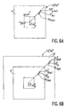
- X-rays k 1 n , X k 2 n are shown on a graph on the abscissa X, and rays Y k 1 n , Y k 2 n are on the ordinate Y, forming pairs P k 1 n , P k 2 n respectively, the optical center OC n being placed at the origin of the coordinate axes graduated in pixels.
- These pairs P k 1 n , P k 2 n form, on this graph, points symbolized by small circles, which are distributed on either side of the curve representative of the polynomial function F "sought.
- FIG. 8A we have limited our to the representation of two pairs of rays for the clarity of the drawing.
- the function F n most suitable for connecting the pairs of X-rays n / k, Y n / k to the iteration n was a polynomial of degree 5 or 6; a polynomial of degree 3 for example is not enough to solve this problem. It appeared that the correction of the radial distortions required the calculation of a polynomial of order greater than 3.
- the best radial correction polynomial F n is calculated to minimize the modeling error E n , by a classic linear regression operation.
- a modeling error E n is calculated at each of the iterations from 0 to, for example, 10. And these modeling errors E 0 , E 1 ... E 10 are stored. Among the different modeling errors calculated during the 10 iteration cycles taken as an example, one of them, in a numbered iteration Nopt, turns out to be lower than the other errors calculated in previous iterations and possibly in subsequent iterations.
- This minimum error E Nopt is stored at the same time as the radial correction polynomial F Nopt , or else its rectangular components F x Nopt , F y Nopt .
- the best position of the optical center OC n to obtain this minimization can be sought in several ways.
- a wide search area is defined around the starting optical center which was noted OC 0 at zero iteration. During each iteration, one of the points of this wide search area is tested, to constitute an optical center. We perform as many iterations as points to test in the wide search area (FULL SEARCH). One finally retains as optical center that which corresponds to the weakest modeling error.
- a second method, less costly in computation time, is based on the computation of gradients.
- a first location then a second location are tried, in a given direction from the first optical center 0C 0 .
- the best position of the optical center continues to be sought in the same direction and the same direction, or else in the same direction and in direction opposite.
- other directions are tried making a given angle with the first direction and finally we retain the iteration where, in a given direction and direction, we found the best optical center to minimize the modeling error.
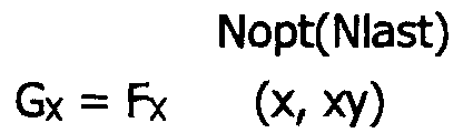
- the components G X and G Y are transformation formulas which pass from the rectified space denoted target image TI, to the distorted space denoted source image SI of origin.
- the coordinates of each pixel x TI and y TI in the fixed reference frame ⁇ x, ⁇ y, are stored.
- the TI image is then scanned pixel by pixel, for example by usual video scanning.
- the level of monochromatic light or gray level is calculated for this point by interpolation from the intensity of its neighboring pixels in this source image. Then the intensity value calculated by interpolation is assigned to the current pixel at the address x TI , y TI in the target image and is stored in the second image memory.
Landscapes
- Engineering & Computer Science (AREA)
- Multimedia (AREA)
- Signal Processing (AREA)
- Physics & Mathematics (AREA)
- General Physics & Mathematics (AREA)
- Theoretical Computer Science (AREA)
- Image Processing (AREA)
- Length Measuring Devices By Optical Means (AREA)
Description
- des lois de correction géométriques des distorsions produites par le système 1 de prise de vue,
- et la localisation précise du centre des distorsions géométriques, qui est aussi le centre optique du système à lentilles de la caméra, dans la plupart des cas.
- une méthode pour déterminer ces lois de correction des distorsions géométriques et pour déterminer de façon concomitante la localisation précise du centre de distorsion, mise en oeuvre dans le premier sous-ensemble 4,
- une méthode pour construire l'image cible TI en utilisant ces connaissances, mise en oeuvre dans le second sous-ensemble 47.
- rendre le support plan de la mire M perpendiculaire à l'axe optique X'X de la caméra de prise de vue, comme illustré par la FIG.1B ;
- rendre les barreaux de la grille parallèles aux lignes et aux colonnes de l'élément à CCD de la caméra 2, comme illustré par la FIG.1C ;
- placer le plan support de la grille de telle sorte que tout le plan image de la caméra soit couvert par des mailles de grille, comme illustré par la FIG.3A.
- pour les points de référence Rk, k est un indice qui permet de numéroter les points de référence de la grille source ; ces numéros peuvent être 1 à 500 par exemple,
- pour les images de la grille source, par exemple SG-2, l'exposant permet de numéroter l'étape du traitement d'image. Ici l'exposant (-2) indique que cette étape est la deuxième avant celle qui fournira l'image de grille source SG0 des lois et du centre recherchés.
- un filtrage de l'image source pour rehausser l'intensité des zones d'intersection,
- un seuillage de l'image filtrée ;
- une labellisation des points seuillés pour former des zones, et une extraction du barycentre de chaque zone.
- ne produit pas de tache d'éblouissement,
- est très robuste à la distorsion de l'intersection,
- il est facile à mettre en oeuvre.
- C le centre du filtre,
- S, N, E, W quatre points cardinaux,
- SE, SW, NE, NW quatre points en diagonale.
- d1 et la distance mesurée en pixels entre le centre C et les points cardinaux (d1 = C-S, C-N, C-E, C-W),
- d2 est la distance mesurée en pixels entre le centre C et les points en diagonale (d2 = C-SE, C-SW, C-NE, C-NW).
- le comptage du nombre N1 des intersections dans l'image,
- le comptage, compte tenu de la numérisation, du nombre N2 approximatif de pixels contenus dans une zone d'intersection : chaque zone d'intersection a quatre côtés, et sa surface est donnée par le produit des épaisseurs en pixels des barreaux de grille horizontaux et verticaux dans l'image distordue, comme montré par exemple sur la FIG.4A,
- le calcul du nombre Nb recherché égal au produit du nombre d'intersections N1 dans l'image distordue par le nombre de pixels approximatif N2 dans une zone d'intersection.
- une estimation d'un point appelé centre de grille cible, noté GC0, localisé à une intersection d'un barreau horizontal et d'un barreau vertical de cette première grille théorique. Il est repéré par ses coordonnées en pixels gcx0, et gcy0 dans un repère orthogonal Ωx, Ωy de la première grille théorique, dont l'axe des x est parallèle aux lignes de pixels et l'axe des y est parallèle aux colonnes de pixels, et dont l'origine correspond à l'origine Ω du repère fixe dans l'image source SG0,
- une détermination de la position d'un centre optique 0C0 considéré comme un centre de distorsion approximatif pour cette première grille théorique TG0.
- une estimation d'un pas GM0 pour cette première grille théorique, défini par les distances en pixels gmx0, gmy0 entre les intersections de barreaux de cette première grille cible, selon l'axe des x et selon l'axe des y, dans le repère fixe Ωx, Ωy,
- une mise en correspondance de points TR 0 / m de la première grille théorique avec des points de référence Rk de la grille source distordue SG0. La localisation de ces points TR 0 / m situés à l'intersection des barreaux de la première grille théorique, est définie à partir des estimations du centre GC0 et du pas GM0 réalisés pour cette première grille théorique.
- une estimation d'un point de référence de départ R 0 / k dans l'image de la grille source SG0, proche du centre de distorsion,
- le report de ce point de départ R 0 / k comme centre de grille GC0 et comme centre optique approximatif 0C0 dans l'image de la première grille théorique TG0. Le centre optique de la première grille théorique est différent du centre optique de la caméra 1, 2 de la FIG.1A.
- un sous-ensemble horizontal noté HS 0 / ka composé de points de référence situés sur le même barreau de grille horizontal dans l'image source, que le point de référence de départ R 0 / ka,
- un sous-ensemble vertical noté VSka composé de points de référence situés sur le même barreau de grille vertical dans l'image source que le point de référence de départ R 0 / ka.

- plus la mesure représentée par ce critère AL(ka) est grande, et plus il existe des points appartenant à cet ensemble S 0 / ka. Donc, plus il existe des points de référence de la grille source SG0 suffisamment bien alignés avec le point de référence testé, pour ne pas dépasser, avec ce point R 0 / ka testé, une distance géométrique égale à la moitié de la composante du pas approximatif gmx-1 horizontalement, et gmy-1 verticalement,
- ce critère est donc une description naturellement bonne d'une région peu distordue.
- un premier filtrage pour déterminer une valeur grossière d'un pas GM00 de la première grille théorique,
- un deuxième filtrage pour déterminer une valeur plus précise d'un pas GM0 pour la construction de la première grille théorique TG0.
- un sous-ensemble horizontal noté HS 0 / k composé des points de référence situés sur le même barreau horizontal que le point de référence R 0 / k dans l'image source SG0, délimité par une bande horizontale de hauteur gmy-1 qui est la composante verticale du pas de grille approximatif GM-1 ;
- un sous-ensemble vertical noté VSk composé des points de référence situés sur le même barreau vertical que le point de référence R 0 / k dans l'image source SG0, délimité par une bande verticale de largeur gmx-1 qui est la composante horizontale du pas de grille approximatif GM-1.
- en calculant la composante gmx00 selon l'axe des Ωx du repère fixe comme le résultat du filtrage par un filtre médian appliqué sur les distances HD 0 / k entre les points de référence du sous-ensemble horizontal HS 0 / k,
- en calculant la composante gmy00 selon l'axe Ωy du repère fixe comme le résultat du filtrage par un filtre médian appliqué sur les distances entre les points de référence du sous-ensemble vertical HS 0 / k.
- d'une mesure robuste,
- et d'une mesure suffisamment précise d'un pas GM0= (gmx0, gmy0), pour la construction de la première grille théorique. Ces données sont mémorisées.
- le centre de grille GC0 déterminé par les coordonnées d'un point de référence R 0 / k proche du centre de distorsion,
- le centre optique OC0 également déterminé par R 0 / k
- le pas de grille GM0,
- des coordonnées gcx0, gcy0 du centre de grille GC0,
- des composantes gmx0, gmy0 du pas de grille GM0
- la première couronne se compose du centre de grille GC0 lui-même,
- la seconde couronne rectangulaire se compose de ses 8 voisins directs de GC0,
- la troisième couronne rectangulaire se compose de ses 16 seconds voisins de GC0.
- calcul d'un polynôme Fn de correction radiale, mis en oeuvre dans le bloc 44),
- calcul de l'erreur En de modélisation et mémorisation de l'optimum, mis en oeuvre dans le bloc 45,
- modification du centre optique OCn mise en oeuvre dans le bloc 46,
- estimation d'une nouvelle grille théorique TGn, mis en oeuvre dans le bloc 43.
- on calcule d'abord, dans le bloc 44, un polynôme F0 de correction des distorsions radiales,
- on calcule ensuite dans le bloc 45, une erreur E0 de modélisation,
- on modifie alors, dans le bloc 46 fermant la boucle, la position du centre optique approximatif qui était 0C0 dans la première grille théorique et que l'on déplace en OC1 pour chercher à le rapprocher d'une position idéale où l'hypothèse radiale est vérifiée, c'est-à-dire où les points de grille théorique sont alignés avec les points de référence et avec le centre optique, comme montré sur la FIG.3D,
- ayant modifié le centre optique maintenant noté OC1, on réestime dans le bloc 43 les éléments de construction d'une seconde grille théorique TG1 définie par son centre de grille GC1, son pas de grille GM1 ; on construit cette seconde grille théorique TG1 au moyen de ces nouveaux élément GC1 et GM1, puis toujours dans ce bloc 43, on réalise la mise en correspondance des nouveaux points de grille théorique TR 1 / g(k) et des points de référence de l'image source SG0,
- à ce moment là, on poursuit le procédé d'itération dans le bloc 44 par le calcul du polynôme F1 de correction des distorsions radiales, puis dans le bloc 45 par le calcul de l'erreur E1 de modélisation et on reboucle l'itération dans le bloc 46 par la modification du centre optique qui devient OC2, etc.
- du centre de grille GCn-1 = (gcxn-1, gcyn-1),
- du pas de grille théorique GMn-1 = (gmxn-1, gmyn-1)
- un centre de grille amélioré GCn = (gcxn, gcyn)
- et un pas de grille amélioré GMn = (gmxn, gmyn),

- départ avec une valeur raisonnable du pas de grille GMn-1, en posant dans le critère radial Φn, les composantes gmxn-1 et gmyy-1 du pas de grille fixes,
- minimisation du critère radial Φn, par rapport au centre de grille GCn-1 : les composantes gmxn-1, gmyn-1 du pas étant fixes, on dérive la formule du critère radial Φn par rapport aux deux coordonnées variables gcxn-1, gcyn-1 du centre de grille GCn-1. Ce calcul de dérivées fournit deux formules explicites qui donnent des valeurs de coordonnées gcxn et gcyn pour mettre à jour le centre de grille GCn à cette itération n,
- minimisation du critère radial Φn, par rapport au pas de grille GMn-1 : on fixe maintenant les coordonnées gcxn et gcyn du centre de grille qui viennent d'être calculée, et on dérive la formule du critère radial Φn par rapport aux composantes du pas de grille variables gmxn-1, gmyn-1. Ce calcul de dérivées fournit à nouveau deux formules explicites qui donnent des valeurs de composantes gmxn et gmyn pour mettre à jour le pas de grille GMn à cette itération n,
- répétition de ces opération autant de fois que nécessaire jusqu'à l'obtention d'une précision requise.
- une mise à jour des coordonnées du centre de grille GCn = (gcxn, gcyn)
- une mise à jour des composantes du pas de grille GMn = (gmxn, gmyn)
- la position du centre optique OCn provenant du bloc 46.
- un premier rayon X n / k ayant pour valeur la longueur du segment qui lie le centre optique OCn et point de grille TG n / g(k) d'un de ces couples P n / k;
- un second rayon Y n / k ayant pour valeur la longueur du segment qui lie le centre optique OCn et le point de référence Rf(k) de ce couple P n / k.

- d'un point TR n / g(k)de la grille théorique corrigée,
- à un point de référence Rf(k) de la grille source distordue.

Claims (8)
- Dispositif de formation d'image comprenant :dans lequel, le système de traitement d'image comprend:un système de prise de vue (1),un système de saisie (2) des données d'une image source (SI) distordue par le système de prise de vues,un système de numérisation (3) de ladite image source (SI) incluant une première mémoire d'image pour le stockage des données d'intensité de chaque pixel repéré par une adresse dans une matrice bidimensionnelle,un système de traitement d'image numérique (4,47) de construction d'une image cible (TI) corrigée en distorsions, correspondant à l'image source (SI),caractérisé en ce le premier sous-ensemble (4) comprend:un premier sous-ensemble (4) de détermination préalable à partir des données d'image d'une image source TEST distordue (SG-2), d'un centre optique (OCn) et d'une fonction polynomiale (FNopt/NLast) de correction des distorsions radiales autour de ce centre optique,un second sous-ensemble (47) incluant une mémoire de stockage du centre optique et de la fonction polynomiale déterminés par le premier sous-ensemble, un bloc de calcul qui applique la fonction polynomiale de correction à chaque adresse de pixel de l'image cible (TI) pour fournir l'adresse d'un point dans l'image source distordue (SI) où trouver une donnée d'intensité à appliquer à l'adresse de départ dans l'image cible, etune seconde mémoire d'image pour le stockage des données de l'image cible (TI) reconstruite;des blocs de traitement de l'image source TEST, ladite image source TEST étant en forme de grille appelée grille source (SG0), pour construire une image cible TEST appelée grille théorique (TGn), lesdits blocs de traitement incluant:un bloc d'extraction (41) de points de référence (Rk) aux intersections des barreaux de la grille source (SG0),un bloc d'estimation (42) d'une première grille théorique (TG0) approchée, calculant l'adresse d'un centre (GC0) et la grandeur d'un pas (GM0) de ladite première grille théorique (TG0),un bloc d'estimation (43) d'une grille théorique (TGn) corrigée en distorsion, calculant par itération l'adresse d'un centre (GCn) et la grandeur d'un pas (GMn) de ladite grille théorique corrigée (TGn),un bloc de calcul (44) d'un polynôme de correction des distorsions radiales fournissant une loi de transformation pour passer d'un point de la grille théorique corrigée à l'itération n (TGn) à un point de référence (Rk) de la grille source distordue, loi de transformation à l'itération n,un bloc de calcul (45) d'une erreur de modélisation (En) due à la loi de transformation à l'itération n,un bloc de calcul (46) d'une adresse modifiée du centre optique (Ocn) qui minimise l'erreur de modélisation.
- Procédé pour mettre en oeuvre le dispositif selon la Revendication 1, pour effectuer des corrections des distorsions optiques géométriques produites dans une image par un système de prise de vue, ce procédé comprenant des étapes préliminaires de :et dans l'étape a) préliminaire de saisie de données et numérisation, l'image source TEST est l'image numérisée d'une grille à mailles rectangulaires dont les barreaux sont parallèles aux lignes et colonnes de pixels, aux erreurs de distorsions optiques près, référencée grille source,a) saisie des données et numérisation d'une image source TEST (SG0), incluant le stockage des données d'intensité de chaque pixel repéré par une adresse dans une matrice bidimensionnelle,b) estimation d'un centre optique (OCn) localisé au mieux au centre des distorsions optiques de l'image source TEST (SG0) et report de ce centre optique dans une image numérique à construire (TGn), référencée image TEST cible, représentant l'image source TEST corrigée des distorsions optiques,c) estimation d'une fonction polynomiale (Fn) pour faire correspondre à l'adresse d'un pixel (TR n / m) dans l'image TEST cible corrigée, l'adresse d'un point correspondant (Rk), noté point de référence, dans l'image source TEST distordue, en se fondant sur l'hypothèse de base que les distorsions optiques géométriques dans l'image source TEST sont radiales autour du centre de distorsion, de sorte que lesdits points correspondants (TR n / m, Rk) sont alignés au mieux avec le centre optique estimé (OCn);
ce procédé comprenant en outre, dans les étapes préliminaires, des étapes itératives de :d) estimation de la meilleure fonction polynomiale (FNopt) capable de minimiser, à une itération d'ordre Nopt, l'erreur de modélisation (En) réalisée sur la localisation des pixels de l'image TEST cible (TGn) construite à une itération précédente (n) selon l'hypothèse des distorsions radiales autour d'un centre optique (OCn) estimé à ladite itération précédente,e) estimation, à une itération d'ordre Nlast, d'un centre optique modifié optimisé (OCNlast) et réestimation dans ces conditions d'une nouvelle fonction polynomiale (FNopt(Nlast)) capable de minimiser davantage l'erreur de modélisation réalisée sur la localisation des pixels de l'image cible reconstruite selon l'hypothèse des distorsions radiales autour dudit meilleur centre optique (OCNlast) estimé;
et dans l'étape b) l'estimation d'un centre optique (OCn) est effectuée de manière itérative à partir d'une itération zéro comprenant la construction d'une première image TEST cible corrigée en distorsion, notée première grille cible (TG0) au moyen des sous-étapes de :extraction d'un point par zone d'intersection des barreaux de la grille source, ces points extraits étant notés points de référence (Rk) de la grille source (SG0),estimation d'un point de référence (R 0 / k) le plus proche du centre de distorsions de la grille source,report de ce point de référence (R 0 / k) dans la première grille cible (TG0) pour constituer le premier centre de grille (GC0),estimation d'un premier pas de grille (GM0) pour ladite grille cible (TG0),estimation d'un premier centre optique approximatif (OC0) pour ladite première grille cible (TG0), situé en coïncidence avec ledit point de référence (R 0 / k) reporté et en coïncidence avec le centre de grille (GC0). - Procédé selon la Revendication 2, dans lequel les étapes préliminaires sont faites une fois pour toutes, ce procédé comprenant à l'issue des étapes préliminaires, des étapes de :ao) saisie des données d'une image source (SI)quelconque distordue par le dispositif de prise de vue, et numérisation et stockage des données d'intensité de chaque pixel,f) correction proprement dite des distorsions optiques, en appliquant à une image cible numérique (TI) à construire, la fonction polynomiale (Fn) estimée, de manière à fournir à partir de chaque adresse de cette image cible (TI), une adresse correspondante dans l'image numérique source (SI) distordue où trouver une donnée d'intensité à appliquer à ladite adresse dans l'image cible à construire.
- Procédé selon la revendication 3, dans lequel les étapes préliminaires sont faites une fois pour toutes, ce procédé comprenant à l'issue des étapes préliminaires, des étapes de :ao) saisie des données d'une image source (SI) quelconque distordue par le dispositif de prise de vue, numérisation et stockage des données d'intensité de chaque pixel ;f') correction proprement dite des distorsions optiques, en appliquant, à une image cible numérique (TI) à construire, la fonction polynomiale (FNopt(Nlast)) estimée la meilleure, de manière à fournir à partir de chaque adresse dans cette image cible (TI), une adresse correspondante dans l'image numérique source (SI) distordue où trouver une fonction d'intensité à appliquer à ladite adresse dans l'image cible à construire.
- Procédé selon la revendication 4, dans lequel à l'étape d) l'estimation itérative de la meilleure fonction polynomiale (FNopt) comprend l'estimation à l'itération d'ordre zéro d'une première fonction polynomiale (F0) comprenant les sous-étapes de :construction des points (TR 0 / m) de ladite première grille cible à partir du centre de grille (GC0) et du pas de grille (GM0) pour correspondre aux points de référence (Rk) d'intersection des barreaux de grille source (SG0)mise en correspondance des points de grille (TR 0 / m) de la première grille cible (TG0) et des points de référence (Rk) de la grille source (SG0) en localisant le centre de grille (GC0) en coïncidence avec le point de référence (R 0 / k) le plus proche du centre de distorsion,formation des couples P 0 / k constitués des points de grille (TR 0 / m) et des points de référence (Rk) correspondants, de proche en proche à partir du centre vers les bords de la grille cible (TG0),estimation de couples de rayons (X 0 / k, Y 0 / k) formés de segments joignant le centre optique (OC0) de la première grille cible (TG0) et chaque points des couples points de grille cible-point de référence (TR 0 / m, Rk),calcul de la première fonction polynomiale (F0) comme celle qui relie le mieux les couples de rayons (X 0 / k, Y 0 / k) pour respecter l'hypothèse selon laquelle les distorsions sont radiales autour du centre optique connu (OC0).
- Procédé selon la revendication 5, dans lequel à l'étape d) l'estimation itérative de la meilleure fonction polynomiale (FNopt) comprend l'estimation à une itération d'ordre n > 0, d'une fonction polynomiale (Fn) comprenant les sous-étapes de :construction d'une grille cible (TGn) à l'ordre n, ayant un centre optique (OCn) et des points de grille (TR n / m) définis par un centre de grille (GCn) et un pas de grille (GMn),mise en correspondance des points de grille (TR n / m) de la grille cible (TGn) et des points de référence (Rk) de la grille source (SGn) en localisant le centre de grille cible (GCn) par ses coordonnées déterminées à l'itération précédente,formation de couples (P n / k) de points de grille (TR n / m)-point de référence (Rk) de proche en proche à partir du centre vers les bords de l'image cible (TGn),estimation des couples de rayons (X n / k, Y n / k) formés des segments joignant le centre optique connu (OCn) et chaque point des couples (TR n / m, Rk),calcul de la fonction polynomiale (Fn) comme celle qui relie le mieux les couples de rayons (X n / k, Y n / k) pour respecter l'hypothèse selon laquelle les distorsions géométriques sont radiales autour du centre optique (OCn).
- Procédé selon la revendication 6, dans lequel la construction d'une grille cible (TGn) à l'itération courante (n) comprend les sous-étapes de :localisation d'un centre optique (OCn) nouvellement mis à jour,localisation des points de grille (TR n-1 / m) et points de référence (Rk) correspondants constituant des couples (P n-1 / k) formés à l'itération précédente (n-1),estimation des distances géométriques (Δ n-1 / k) abscisses des points de grille (TR n-1 / m) sur les rayons passant par le centre optique nouvellement mis à jour (OCn) et par les points de référence correspondants (Rk) des couples (P n-1 / k) formés à cette itération précédente (n-1),estimation d'un critère référencé critère radial n qui exprime l'hypothèse radiale que la meilleure grille cible corrigée correspond à la minimisation des distances géométriques (Δ n-1 / k),minimisation du critère radial n exprimé en fonction des coordonnées du centre et des composantes du pas de la grille à l'itération (n-1), fournissant les coordonnées du centre et les composantes du pas de la. grille cible à l'itération n.
- Procédé selon la revendication 7, dans lequel l'étape e) d'estimation du meilleur centre optique (OCNlast) est réalisée dans une boucle d'itération dans laquelle à chaque itération courante (n) la localisation du centre optique (OCn) est modifiée, puis réintroduite dans la construction de la grille cible courante (TGn) pour la détermination d'une nouvelle fonction polynomiale (Fn) et l'estimation de l'erreur de modélisation (En) correspondante,
la meilleure localisation du centre (OCNlast) étant celle qui résulte en l'erreur de modélisation la plus faible correspondant à la meilleure fonction polynomiale (FNopt(Nlast)).
Applications Claiming Priority (2)
| Application Number | Priority Date | Filing Date | Title |
|---|---|---|---|
| FR9415872 | 1994-12-29 | ||
| FR9415872 | 1994-12-29 |
Publications (2)
| Publication Number | Publication Date |
|---|---|
| EP0720125A1 EP0720125A1 (fr) | 1996-07-03 |
| EP0720125B1 true EP0720125B1 (fr) | 2002-05-08 |
Family
ID=9470416
Family Applications (1)
| Application Number | Title | Priority Date | Filing Date |
|---|---|---|---|
| EP95203550A Expired - Lifetime EP0720125B1 (fr) | 1994-12-29 | 1995-12-19 | Dispositif de formation d'image et procédé pour effectuer des corrections de distorsions optiques géométriques dans une image |
Country Status (4)
| Country | Link |
|---|---|
| US (1) | US5675380A (fr) |
| EP (1) | EP0720125B1 (fr) |
| JP (1) | JPH08287243A (fr) |
| DE (1) | DE69526635T2 (fr) |
Families Citing this family (84)
| Publication number | Priority date | Publication date | Assignee | Title |
|---|---|---|---|---|
| JP3393029B2 (ja) * | 1997-01-20 | 2003-04-07 | 富士通株式会社 | ディスプレイ装置の表示画像歪みの補正方法、歪み検出装置、歪み補正装置、及びその歪み補正装置を備えたディスプレイ装置 |
| US6101288A (en) * | 1997-07-28 | 2000-08-08 | Digital Equipment Corporation | Method for recovering radial distortion parameters from a single camera image |
| US6281931B1 (en) * | 1997-11-04 | 2001-08-28 | Tien Ren Tsao | Method and apparatus for determining and correcting geometric distortions in electronic imaging systems |
| JP2000125174A (ja) * | 1998-10-12 | 2000-04-28 | Fuji Photo Film Co Ltd | 画像情報における歪曲収差補正方法および装置 |
| US6618494B1 (en) * | 1998-11-27 | 2003-09-09 | Wuestec Medical, Inc. | Optical distortion correction in digital imaging |
| DE19856537A1 (de) * | 1998-12-08 | 2000-06-15 | Philips Corp Intellectual Pty | Verfahren zur intraoperativen Kalibration von C-Bogen Röntgenanordnungen |
| US6538691B1 (en) * | 1999-01-21 | 2003-03-25 | Intel Corporation | Software correction of image distortion in digital cameras |
| JP2000241120A (ja) | 1999-02-23 | 2000-09-08 | Fanuc Ltd | 計測装置 |
| US6449397B1 (en) * | 1999-04-05 | 2002-09-10 | Mustek Systems Inc. | Image processing system for scanning a rectangular document |
| US7023472B1 (en) * | 1999-04-23 | 2006-04-04 | Hewlett-Packard Development Company, L.P. | Camera calibration using off-axis illumination and vignetting effects |
| US6437795B1 (en) * | 1999-07-21 | 2002-08-20 | Sun Microsystems, Inc. | Method and apparatus for clipping a function |
| JP4343341B2 (ja) * | 1999-09-01 | 2009-10-14 | オリンパス株式会社 | 内視鏡装置 |
| JP2001290820A (ja) * | 2000-01-31 | 2001-10-19 | Mitsubishi Electric Corp | 映像収集装置、映像検索装置および映像収集検索システム |
| US6536907B1 (en) * | 2000-02-08 | 2003-03-25 | Hewlett-Packard Development Company, L.P. | Aberration compensation in image projection displays |
| AU2001279600A1 (en) | 2000-08-10 | 2002-02-18 | Novo-Nordisk A/S | A support for a cartridge for transferring an electronically readable information to an electronic circuit, and use of composite material in a support |
| US6994261B2 (en) * | 2000-08-10 | 2006-02-07 | Novo Nirdisk A/S | Support for a cartridge for transferring an electronically readable item of information from the cartridge to an electronic circuit |
| WO2002029490A1 (fr) * | 2000-10-04 | 2002-04-11 | Panoram Technologies, Inc. | Systeme de projection pour ecrans en reseau ou en mosaique |
| JP2002216136A (ja) * | 2001-01-23 | 2002-08-02 | Sony Corp | 距離算出方法及び撮像装置 |
| JP2002237998A (ja) * | 2001-02-07 | 2002-08-23 | Sony Corp | 画面補正方法及び撮像装置 |
| JP3804916B2 (ja) * | 2001-02-09 | 2006-08-02 | シャープ株式会社 | 撮像システムとその画像データ制御に用いられるプログラムおよびその撮像システムにおける撮像画像の歪み補正方法とその手順を記憶させた記憶媒体 |
| FI113132B (fi) * | 2001-06-28 | 2004-02-27 | Nokia Corp | Menetelmä ja laite kuvanparannukseen |
| FR2827459B1 (fr) * | 2001-07-12 | 2004-10-29 | Poseidon | Procede et systeme pour fournir a des logiciels de traitement d'image des informations formatees liees aux caracteristiques des appareils de capture d'image et/ou des moyens de restitution d'image |
| ES2282429T3 (es) * | 2001-07-12 | 2007-10-16 | Do Labs | Procedimiento y sistema para producir informaciones formateadas relacionadas con las distorsiones geometricas. |
| EP1326416A1 (fr) * | 2002-01-03 | 2003-07-09 | Fujifilm Electronic Imaging Limited | Compensation de la courbure de champ |
| US6707998B2 (en) | 2002-05-14 | 2004-03-16 | Eastman Kodak Company | Method and system for correcting non-symmetric distortion in an image |
| JP3971246B2 (ja) * | 2002-06-03 | 2007-09-05 | 富士フイルム株式会社 | デジタル撮影装置 |
| DE10224993C1 (de) * | 2002-06-05 | 2003-08-21 | Siemens Ag | Verfahren zur Vermessung der Verzerrung einer Flächen-Positioniervorrichtung |
| US7408576B2 (en) | 2002-08-16 | 2008-08-05 | Zoran Corporation | Techniques for modifying image field data as a function of radius across the image field |
| US7388610B2 (en) | 2002-08-16 | 2008-06-17 | Zoran Corporation | Techniques of modifying image field data by extrapolation |
| US7391450B2 (en) * | 2002-08-16 | 2008-06-24 | Zoran Corporation | Techniques for modifying image field data |
| JP4144292B2 (ja) * | 2002-08-20 | 2008-09-03 | ソニー株式会社 | 画像処理装置と画像処理システム及び画像処理方法 |
| EP1447977A1 (fr) * | 2003-02-12 | 2004-08-18 | Dialog Semiconductor GmbH | Compensation du vignettage |
| DE10306986A1 (de) * | 2003-02-19 | 2004-09-09 | Siemens Ag | Gerät und Verfahren zur Entzerrung eines weitwinklig aufgenommenen Bildes |
| JP4762131B2 (ja) * | 2003-03-24 | 2011-08-31 | ノボ・ノルデイスク・エー/エス | 薬用カートリッジの透明な電子マーキング |
| JP4095491B2 (ja) * | 2003-05-19 | 2008-06-04 | 本田技研工業株式会社 | 距離測定装置、距離測定方法、及び距離測定プログラム |
| US7596286B2 (en) * | 2003-08-06 | 2009-09-29 | Sony Corporation | Image processing apparatus, image processing system, imaging apparatus and image processing method |
| US20060243804A1 (en) * | 2003-10-03 | 2006-11-02 | Novo Nordisk A/S | Container comprising code information elements |
| FR2860601B1 (fr) * | 2003-10-07 | 2005-12-30 | Thales Sa | Procede de correction de distorsion d'un imageur a cristaux liquides |
| JP4071793B2 (ja) | 2003-10-22 | 2008-04-02 | 松下電器産業株式会社 | 撮像装置とその製造方法、及び携帯機器 |
| JP4124096B2 (ja) * | 2003-10-29 | 2008-07-23 | 株式会社ニコン | 画像処理方法および画像処理装置、並びにプログラム |
| JP2005151317A (ja) * | 2003-11-18 | 2005-06-09 | Tamron Co Ltd | 歪曲収差変更撮影装置 |
| CN100446556C (zh) * | 2003-12-26 | 2008-12-24 | 深圳创维-Rgb电子有限公司 | 超大屏全数字光机电引擎光学失真校正方法 |
| JP4104571B2 (ja) * | 2004-03-29 | 2008-06-18 | 三洋電機株式会社 | 歪曲補正装置及びこの歪曲補正装置を備えた撮像装置 |
| US8184923B2 (en) * | 2004-04-19 | 2012-05-22 | Semiconductor Energy Laboratory Co., Ltd. | Image analysis method, image analysis program, pixel evaluation system having the image analysis method, and pixel evaluation system having the image analysis program |
| JP4542821B2 (ja) * | 2004-05-25 | 2010-09-15 | 学校法人愛知学院 | 画像処理方法、画像処理装置、および画像処理プログラム |
| DE602005004332T2 (de) | 2004-06-17 | 2009-01-08 | Cadent Ltd. | Verfahren zum Bereitstellen von Daten im Zusammenhang mit der Mundhöhle |
| DE502004005441D1 (de) * | 2004-09-04 | 2007-12-20 | Universitaetsspital Basel Carc | Verfahren und System zur Bildkomposition |
| GB0422585D0 (en) * | 2004-10-12 | 2004-11-10 | Trw Ltd | Sensing apparatus and method for vehicles |
| JP2006127083A (ja) * | 2004-10-28 | 2006-05-18 | Aisin Seiki Co Ltd | 画像処理方法及び画像処理装置 |
| DE602006019712D1 (fr) * | 2005-05-10 | 2011-03-03 | Novo Nordisk As | |
| US7839446B2 (en) * | 2005-08-30 | 2010-11-23 | Olympus Corporation | Image capturing apparatus and image display apparatus including imparting distortion to a captured image |
| RU2432549C2 (ru) | 2005-09-22 | 2011-10-27 | Ново Нордиск А/С | Способ и прибор для бесконтактного определения абсолютного положения и устройство, снабженное данным прибором |
| US7912317B2 (en) * | 2005-10-29 | 2011-03-22 | Apple Inc. | Estimating and removing lens distortion from scenes |
| FR2894685A3 (fr) * | 2005-12-09 | 2007-06-15 | 6115187 Canada Inc | Procede et dispositif d'identification et de calibration d'optiques panoramiques |
| CN101405749B (zh) | 2006-03-20 | 2012-05-30 | 诺沃—诺迪斯克有限公司 | 套筒及在套筒插入到其中时的药物输送装置 |
| EP2011223B1 (fr) | 2006-04-12 | 2018-06-13 | Novo Nordisk A/S | Détermination de la position absolue d'un membre monté de manière mobile dans un dispositif pour administrer un médicament |
| BRPI0710915A2 (pt) | 2006-04-26 | 2011-09-27 | Novo Nordisk As | dispositivo de distribuição de medicação e método para determinar posições absolutas de um primeiro membro em relação a um segundo membro de um dispositivo de distribuição de medicação |
| KR100744937B1 (ko) | 2006-06-29 | 2007-08-01 | 삼성전기주식회사 | 렌즈 왜곡 보정 방법 |
| JP4977556B2 (ja) * | 2006-10-11 | 2012-07-18 | ルネサスエレクトロニクス株式会社 | 半導体集積回路装置および描画処理表示システム |
| US8348904B2 (en) | 2007-03-21 | 2013-01-08 | Novo Nordisk A/S | Medical delivery system having container recognition and container for use with the medical delivery system |
| FR2914099B1 (fr) * | 2007-03-22 | 2013-04-05 | Eads Test & Services | Systeme de test universel apte a controler une pluralite de parametres relatifs au fonctionnement de dispositif de presentation d'informations optoelectroniques de types varies |
| BRPI0817024A2 (pt) * | 2007-09-21 | 2015-03-24 | Koninkl Philips Electronics Nv | Método para realçar uma estrutura móvel de interesse em uma seqüência de imagens, sistema de geração de imagem, meio legível por computador, elemento de programa, método para exibir uma seqüência de imagens, dispositivo de exibição, e, seqüência de imagens |
| DE502007006045D1 (de) * | 2007-10-26 | 2011-02-03 | Sick Ag | Ortsauflösender optoelektronischer Sensor mit Testeinheit und Testverfahren hierfür |
| JP5020894B2 (ja) * | 2008-06-10 | 2012-09-05 | キヤノン株式会社 | 画像処理装置、制御方法、及びプログラム |
| JP5562969B2 (ja) | 2008-11-06 | 2014-07-30 | ノボ・ノルデイスク・エー/エス | 電子的に支援された薬剤送達装置 |
| EP2396059B1 (fr) | 2009-02-13 | 2014-01-08 | Novo Nordisk A/S | Dispositif médical et cartouche |
| US8872887B2 (en) * | 2010-03-05 | 2014-10-28 | Fotonation Limited | Object detection and rendering for wide field of view (WFOV) image acquisition systems |
| US8675115B1 (en) | 2011-02-14 | 2014-03-18 | DigitalOptics Corporation Europe Limited | Forward interpolation approach for constructing a second version of an image from a first version of the image |
| US8577186B1 (en) * | 2011-02-14 | 2013-11-05 | DigitalOptics Corporation Europe Limited | Forward interpolation approach using forward and backward mapping |
| US8340462B1 (en) * | 2011-02-14 | 2012-12-25 | DigitalOptics Corporation Europe Limited | Pixel mapping using a lookup table and linear approximation |
| US8723959B2 (en) | 2011-03-31 | 2014-05-13 | DigitalOptics Corporation Europe Limited | Face and other object tracking in off-center peripheral regions for nonlinear lens geometries |
| US8982180B2 (en) * | 2011-03-31 | 2015-03-17 | Fotonation Limited | Face and other object detection and tracking in off-center peripheral regions for nonlinear lens geometries |
| US8860816B2 (en) * | 2011-03-31 | 2014-10-14 | Fotonation Limited | Scene enhancements in off-center peripheral regions for nonlinear lens geometries |
| CN105326498A (zh) * | 2011-09-08 | 2016-02-17 | Apn健康有限责任公司 | R波检测方法 |
| JP5924020B2 (ja) * | 2012-02-16 | 2016-05-25 | セイコーエプソン株式会社 | プロジェクター、及び、プロジェクターの制御方法 |
| CN103674244B (zh) * | 2013-07-05 | 2015-10-21 | 北京师范大学 | 一种基于gpu的快速反卷积二维光纤光谱抽取方法 |
| CN106596063B (zh) * | 2014-06-27 | 2019-05-24 | 歌尔科技有限公司 | 一种测量透镜畸变的方法及系统 |
| US9675430B2 (en) | 2014-08-15 | 2017-06-13 | Align Technology, Inc. | Confocal imaging apparatus with curved focal surface |
| CN104239861A (zh) * | 2014-09-10 | 2014-12-24 | 深圳市易讯天空网络技术有限公司 | 卷曲文本图像预处理方法和彩票扫描识别方法 |
| JP2016103169A (ja) * | 2014-11-28 | 2016-06-02 | 株式会社リコー | 画像処理装置、画像処理方法および電子機器 |
| CN109443697B (zh) * | 2018-09-29 | 2021-10-15 | 歌尔光学科技有限公司 | 光学中心测试方法、装置、系统和设备 |
| CN112907677B (zh) * | 2019-12-04 | 2023-07-25 | 杭州海康威视数字技术股份有限公司 | 一种单帧图像的相机标定方法、装置及存储介质 |
| JP7633014B2 (ja) * | 2020-10-26 | 2025-02-19 | 住友重機械工業株式会社 | 歪曲収差補正処理装置、歪曲収差補正方法、及びプログラム |
| CN112288659B (zh) * | 2020-12-18 | 2021-03-23 | 南京佗道医疗科技有限公司 | 一种透视图像矫正方法 |
Family Cites Families (9)
| Publication number | Priority date | Publication date | Assignee | Title |
|---|---|---|---|---|
| JPS59125176A (ja) * | 1982-12-30 | 1984-07-19 | インタ−ナシヨナル ビジネス マシ−ンズ コ−ポレ−シヨン | ビデオイメ−ジのシエ−ジング効果の補正装置 |
| US5235528A (en) * | 1990-10-05 | 1993-08-10 | Kabushiki Kaisha Toshiba | Method and apparatus for calibrating and correcting magnetic and geometrical distortions in an imaging system |
| JP2956213B2 (ja) * | 1990-11-30 | 1999-10-04 | ソニー株式会社 | 画像処理装置 |
| EP0543980A1 (fr) * | 1991-05-10 | 1993-06-02 | Eastman Kodak Company | Circuit integre a applications specifiques personnalisable a fonctions de commande et de synchronisation utilise en imagerie electronique |
| EP0518185B1 (fr) * | 1991-06-10 | 1996-12-11 | Eastman Kodak Company | Système d'alignement de détecteur d'image par correlation croisée |
| GB2256989B (en) | 1991-06-21 | 1995-02-08 | Sony Broadcast & Communication | Video image capture apparatus |
| GB2263379B (en) * | 1992-01-10 | 1995-07-26 | Ceramaspeed Ltd | Radiant heater having multiple heating zones |
| EP0605045B1 (fr) * | 1992-12-29 | 1999-03-31 | Laboratoires D'electronique Philips S.A.S. | Procédé et dispositif de traitement d'images pour construire une image à partir d'images adjacentes |
| US5444794A (en) * | 1993-08-25 | 1995-08-22 | Sqn | Check image capture system |
-
1995
- 1995-12-19 EP EP95203550A patent/EP0720125B1/fr not_active Expired - Lifetime
- 1995-12-19 DE DE69526635T patent/DE69526635T2/de not_active Expired - Fee Related
- 1995-12-20 US US08/575,537 patent/US5675380A/en not_active Expired - Fee Related
- 1995-12-26 JP JP7339236A patent/JPH08287243A/ja not_active Abandoned
Also Published As
| Publication number | Publication date |
|---|---|
| EP0720125A1 (fr) | 1996-07-03 |
| DE69526635D1 (de) | 2002-06-13 |
| JPH08287243A (ja) | 1996-11-01 |
| DE69526635T2 (de) | 2002-12-05 |
| US5675380A (en) | 1997-10-07 |
Similar Documents
| Publication | Publication Date | Title |
|---|---|---|
| EP0720125B1 (fr) | Dispositif de formation d'image et procédé pour effectuer des corrections de distorsions optiques géométriques dans une image | |
| CN115398469B (zh) | 图像处理方法及图像处理装置 | |
| EP3412245B1 (fr) | Procédé d'évaluation d'une goutière orthodontique | |
| EP0650299B1 (fr) | Procédé de traitement des niveaux de luminance dans une image composite et système de traitement d'image appliquant ce procédé | |
| CN110023810B (zh) | 光学系统像差的数字校正 | |
| JP5153846B2 (ja) | 画像処理装置、撮像装置、画像処理方法、及び、プログラム | |
| EP3114831B1 (fr) | Débruitage vidéo optimisé pour système multicapteur hétérogène | |
| EP0692772A1 (fr) | Procédé et dispositif pour détecter des points clés situés sur le contour d'un objet | |
| EP0755023A1 (fr) | Procédé de filtrage spatial du bruit dans une image numérique, et dispositif mettant en oeuvre ce procédé | |
| KR20050107741A (ko) | 이미지 인해스먼트 기능을 가진 카메라 | |
| WO2015166176A1 (fr) | Procédé de suivi de forme dans une scène observée par un capteur asynchrone de lumière | |
| WO2015071457A1 (fr) | Procede d'estimation de la vitesse de deplacement d'une camera | |
| FR2652695A1 (fr) | Procede et dispositif de visualisation d'images, a correction automatique de defauts par contre-reaction. | |
| EP1523731A1 (fr) | Procede de traitement d'une image acquise au moyen d'un guide compose d'une pluralite de fibres optiques | |
| EP3657784A1 (fr) | Procédé d'estimation d'un défaut d'un système de capture d'images et systèmes associés | |
| EP3314888A1 (fr) | Correction de pixels parasites dans un capteur d'image infrarouge | |
| FR2657208A1 (fr) | Procede et dispositif de correction automatique de geometrie, de superposition de couleurs et d'uniformite d'image pour camera de television. | |
| JP5587264B2 (ja) | 調整方法、調整装置、及び、撮像装置の製造方法 | |
| EP3301644B1 (fr) | Procédé de construction d'une carte de profondeur d'une scène et/ou d'une image entièrement focalisée | |
| JP2013033496A (ja) | 画像処理装置、撮像装置、画像処理方法、及び、プログラム | |
| KR102584209B1 (ko) | 오목 렌즈 배열을 이용한 집적 영상의 3차원 재구성 방법 | |
| EP3054422A1 (fr) | Procédé de determination d'un axe de rotation d'un objet en tomographie et procédé de caracterisation par tomographie | |
| WO2020094441A1 (fr) | Capteur d'image pour la reconnaissance optique de code(s) | |
| JP2018088587A (ja) | 画像処理方法および画像処理装置 | |
| FR3135553A1 (fr) | Procédé de correction globale d’une image, et système associé |
Legal Events
| Date | Code | Title | Description |
|---|---|---|---|
| PUAI | Public reference made under article 153(3) epc to a published international application that has entered the european phase |
Free format text: ORIGINAL CODE: 0009012 |
|
| AK | Designated contracting states |
Kind code of ref document: A1 Designated state(s): DE FR GB IE |
|
| 17P | Request for examination filed |
Effective date: 19970103 |
|
| RAP1 | Party data changed (applicant data changed or rights of an application transferred) |
Owner name: KONINKLIJKE PHILIPS ELECTRONICS N.V. |
|
| 17Q | First examination report despatched |
Effective date: 20000526 |
|
| GRAG | Despatch of communication of intention to grant |
Free format text: ORIGINAL CODE: EPIDOS AGRA |
|
| GRAG | Despatch of communication of intention to grant |
Free format text: ORIGINAL CODE: EPIDOS AGRA |
|
| GRAH | Despatch of communication of intention to grant a patent |
Free format text: ORIGINAL CODE: EPIDOS IGRA |
|
| REG | Reference to a national code |
Ref country code: GB Ref legal event code: IF02 |
|
| GRAH | Despatch of communication of intention to grant a patent |
Free format text: ORIGINAL CODE: EPIDOS IGRA |
|
| GRAA | (expected) grant |
Free format text: ORIGINAL CODE: 0009210 |
|
| AK | Designated contracting states |
Kind code of ref document: B1 Designated state(s): DE FR GB IE |
|
| PG25 | Lapsed in a contracting state [announced via postgrant information from national office to epo] |
Ref country code: IE Free format text: LAPSE BECAUSE OF FAILURE TO SUBMIT A TRANSLATION OF THE DESCRIPTION OR TO PAY THE FEE WITHIN THE PRESCRIBED TIME-LIMIT Effective date: 20020508 |
|
| REG | Reference to a national code |
Ref country code: IE Ref legal event code: FG4D Free format text: FRENCH |
|
| REF | Corresponds to: |
Ref document number: 69526635 Country of ref document: DE Date of ref document: 20020613 |
|
| GBT | Gb: translation of ep patent filed (gb section 77(6)(a)/1977) |
Effective date: 20020720 |
|
| REG | Reference to a national code |
Ref country code: GB Ref legal event code: 746 Effective date: 20020919 |
|
| REG | Reference to a national code |
Ref country code: FR Ref legal event code: D6 |
|
| REG | Reference to a national code |
Ref country code: IE Ref legal event code: FD4D Ref document number: 0720125E Country of ref document: IE |
|
| PLBE | No opposition filed within time limit |
Free format text: ORIGINAL CODE: 0009261 |
|
| STAA | Information on the status of an ep patent application or granted ep patent |
Free format text: STATUS: NO OPPOSITION FILED WITHIN TIME LIMIT |
|
| 26N | No opposition filed |
Effective date: 20030211 |
|
| PGFP | Annual fee paid to national office [announced via postgrant information from national office to epo] |
Ref country code: GB Payment date: 20031224 Year of fee payment: 9 |
|
| PGFP | Annual fee paid to national office [announced via postgrant information from national office to epo] |
Ref country code: FR Payment date: 20031229 Year of fee payment: 9 |
|
| PGFP | Annual fee paid to national office [announced via postgrant information from national office to epo] |
Ref country code: DE Payment date: 20040216 Year of fee payment: 9 |
|
| PG25 | Lapsed in a contracting state [announced via postgrant information from national office to epo] |
Ref country code: GB Free format text: LAPSE BECAUSE OF NON-PAYMENT OF DUE FEES Effective date: 20041219 |
|
| PG25 | Lapsed in a contracting state [announced via postgrant information from national office to epo] |
Ref country code: DE Free format text: LAPSE BECAUSE OF NON-PAYMENT OF DUE FEES Effective date: 20050701 |
|
| GBPC | Gb: european patent ceased through non-payment of renewal fee |
Effective date: 20041219 |
|
| PG25 | Lapsed in a contracting state [announced via postgrant information from national office to epo] |
Ref country code: FR Free format text: LAPSE BECAUSE OF NON-PAYMENT OF DUE FEES Effective date: 20050831 |
|
| REG | Reference to a national code |
Ref country code: FR Ref legal event code: ST |