EP0720355B1 - Appareil pour déterminer des vecteurs de déplacement à l'aide d'un filtre médian adaptif - Google Patents
Appareil pour déterminer des vecteurs de déplacement à l'aide d'un filtre médian adaptif Download PDFInfo
- Publication number
- EP0720355B1 EP0720355B1 EP95100028A EP95100028A EP0720355B1 EP 0720355 B1 EP0720355 B1 EP 0720355B1 EP 95100028 A EP95100028 A EP 95100028A EP 95100028 A EP95100028 A EP 95100028A EP 0720355 B1 EP0720355 B1 EP 0720355B1
- Authority
- EP
- European Patent Office
- Prior art keywords
- vectors
- major
- motion vector
- center
- motion
- Prior art date
- Legal status (The legal status is an assumption and is not a legal conclusion. Google has not performed a legal analysis and makes no representation as to the accuracy of the status listed.)
- Expired - Lifetime
Links
Images
Classifications
-
- H—ELECTRICITY
- H04—ELECTRIC COMMUNICATION TECHNIQUE
- H04N—PICTORIAL COMMUNICATION, e.g. TELEVISION
- H04N5/00—Details of television systems
- H04N5/14—Picture signal circuitry for video frequency region
- H04N5/144—Movement detection
- H04N5/145—Movement estimation
-
- G—PHYSICS
- G06—COMPUTING OR CALCULATING; COUNTING
- G06T—IMAGE DATA PROCESSING OR GENERATION, IN GENERAL
- G06T7/00—Image analysis
- G06T7/20—Analysis of motion
- G06T7/223—Analysis of motion using block-matching
- G06T7/231—Analysis of motion using block-matching using full search
-
- H—ELECTRICITY
- H04—ELECTRIC COMMUNICATION TECHNIQUE
- H04N—PICTORIAL COMMUNICATION, e.g. TELEVISION
- H04N19/00—Methods or arrangements for coding, decoding, compressing or decompressing digital video signals
- H04N19/50—Methods or arrangements for coding, decoding, compressing or decompressing digital video signals using predictive coding
- H04N19/503—Methods or arrangements for coding, decoding, compressing or decompressing digital video signals using predictive coding involving temporal prediction
- H04N19/51—Motion estimation or motion compensation
-
- G—PHYSICS
- G06—COMPUTING OR CALCULATING; COUNTING
- G06T—IMAGE DATA PROCESSING OR GENERATION, IN GENERAL
- G06T2207/00—Indexing scheme for image analysis or image enhancement
- G06T2207/10—Image acquisition modality
- G06T2207/10016—Video; Image sequence
Definitions
- the present invention relates to an improved apparatus for determining motion vectors; and, more particularly, to an improved apparatus for determining motion vectors through the use of a median filter employing an adaptive filtering window.
- an image signal may need be transmitted in a digitized form.
- the image signal is expressed in a digitized form, there is bound to occur a substantial amount of digital data. Since, however, the available frequency bandwidth of a conventional transmission channel is limited, in order to transmit the image signal therethrough, it is inevitable to compress or reduce the volume of the transmission data.
- a motion compensated interframe coding technique which utilizes temporal redundancies of the video signals between two adjacent video frames for the compression of the signals, is known to be one of the effective compression techniques.
- current frame data is predicted from previous frame data based on an estimation of a motion between the current and the previous frames.
- estimated motion may be described in terms of two dimensional motion vectors representing the displacement of pixels between the previous and the current frames.
- One of the motion vector estimation schemes which have been proposed in the art is a block matching algorithm( see , e.g., J.R. Jain et al., "Displacement Measurement and Its Application in Interframe Image Coding", IEEE Transactions on Communications COM-29 , No. 12(December 1981)).
- a current frame is divided into a plurality of equal-sized search blocks.
- the size of a search block typically ranges between 8x8 and 32x32 pixels.
- a similarity calculation is performed between the search block of the current frame and each of a multiplicity of equal-sized candidate blocks included in a generally larger search region within a previous frame.
- An error function such as the mean absolute error or mean square error is used to carry out a similarity measurement between the search block of the current frame and each of the candidate blocks in the search region.
- a motion vector by definition, represents the displacement between the search block and a best matching block, i.e., a candidate block which yields a minimum "error" or difference.
- the document EP-A-466 981 discloses a motion vector processing device including filter means for median-filtering the motion vectors to generate filtered motion vectors for pixels included in the current frame.
- an apparatus for use in a motion-compensated video signal encoder, for determining motion vectors representing a displacement between a current frame and a reference frame of video signals, wherein the current frame is divided into a plurality of processing blocks, each processing block having P x Q pixels with P and Q being integers larger than two, and said P x Q pixels include therein a center pixel located at the center of each processing block, said apparatus comprising: means for providing a motion vector for each of the pixels included in the current frame, the motion vectors including center motion vectors, each of the center motion vectors being a motion vector for each of the center pixels; means for detecting edge positions of an object in the current frame to produce edge position signals; filtering means, having a filtering window, for median-filtering the motion vectors to generate filtered motion vectors for the pixels included in the current frame, whereby the filtering means adjusts the size of said filtering window in response to the edge position signals provided by the detecting means; means for counting the number of
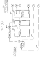
- FIG. 1 there is shown a block diagram of an inventive apparatus for determining a motion vector for each of a plurality of processing blocks included in the current frame, each of the processing block having P x Q, e.g., 7 x 7, pixels.
- Current frame data is fed as an input digital video signal to a frame memory 100 and motion vector estimator 200.
- the reference frame data provided from the frame memory 100 is also fed to the motion estimator 200.
- the motion estimator 200 serves to determine a motion vector for each of the pixels contained in the current frame by using a block matching algorithm. Specifically, in order to determine a motion vector for a pixel("target pixel") included in the current frame, a search block of M x N, e.g., 3 x 3 pixels is set up by using the target pixel as a reference, the target pixel coinciding with the center of the search block. The search block is compared with all of the candidate blocks included in the corresponding search region in the reference frame, on a block-by-block basis, by using the block matching algorithm well known in the art. A displacement for the search block obtained through the use of the block matching algorithm is assigned as a motion vector of the target pixel.
- a block matching algorithm well known in the art.
- Each of the motion vectors corresponding to each pixel included in the current frame is provided from the motion estimator 200 to a median filter 300 for further processing.
- the motion estimator 200 also provides motion vectors of center pixels to a comparator 510 in accordance with the invention, each of the center pixels being a pixel positioned at the center of each processing block if both Q and P are odd numbered integers; one of two pixels at the center thereof if either Q or P is an even numbered integer; and one of four pixels at the center thereof if both Q and P are even numbered integers. That is, the center pixel is one of maximum four pixels located at the center of the processing block.
- the current frame data is also provided to an edge detector 400 which serves to detect edge positions of an object within the current frame.
- the edge detector 400 detects the edge positions of the object in the incoming current frame and generates edge position signals to the median filter 300.
- the operation of the edge detector 400 will not be described in detail herein as it is well known in the art( See , e.g., A.K. Jain, "Fundamentals of Digital Image Processing", 1989, Prentice-Hall International).
- the median filtering operation is performed on each of the motion vectors fed from the motion estimator 200 through the use of an appropriate filtering window.
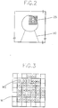
- the median filter 300 has an adaptive filtering window having a variable window size as shown in Fig. 3, wherein the size of the adaptive filtering window varies with the edge position signals provided from the edge detector 400.
- the median filter 300 increasingly expands its filtering window until a boundary of the filtering window includes any of the edges. It can be seen from Fig. 3 that the adaptive filtering window W1 is extended to W2 which includes the edge positions of the object 50 shown in Fig. 2.
- the object in the current frame is illustrated to have a processing block 25 having an center pixel (a). Edge positions of the object 50 contained in the processing block 25 are marked with (X) shown in Fig. 3.
- the median filter 300 averages the motion vectors for the pixels (a) to (y), which are included in the expanded adaptive filtering window W2, by multiplying predetermined filter coefficients thereto; and assigns the averaged value as a filtered motion vector of the center pixel (a).
- Each of the filtered motion vectors corresponding to each of the pixels included in each processing block of the current frame is provided from the median filter 300 to a majority detector 500.
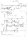
- the majority detector 500 which receives filtered motion vector corresponding to each of the processing blocks of, e.g., 7 x 7 pixels, counts the number of filtered motion vectors having a same value and determines a first and a second major vectors, the first and second major vectors corresponding to filtered motion vectors having the largest and second largest counted numbers, respectively.
- the first and second major vectors are outputted through output terminals 400A and 400C of the majority detector 500, respectively.
- the majority detector 500 outputs the number of the first major vectors through its output terminal 400B.
- a comparator 515 compares the number of the first major vectors from the majority detector 500 with a predetermined value, e.g., 25; and generates a logic high signal to an AND gate 520 if the number of the first major vector is not smaller than 25; otherwise, it generates a logic low signal to the AND gate 520.
- the comparator 510 compares the first major vector provided from the output terminal 400A with the motion vector of the center pixel fed from the motion estimator 200; and produces a logic high signal to the AND gate 520 if they are identical; otherwise it produces a logic low signal.
- the AND gate 520 In response to the output signals from the comparators 510 and 515, the AND gate 520 generates, as a control signal CTL of a switch 530, a logic high signal if both of the output signals from the comparators 510 and 515 are logic high and a logic low signal if otherwise.
- the inventive apparatus further includes a vector selection block 600 for selecting among the first and second major vectors a major vector which generates a motion-compensated processing block having a less error function, e.g., mean square error.
- the vector selection block 600 comprises predictors 610 and 615 and mean square error(MSE) detectors 620 and 625.
- the first and second major vectors are provided from the majority detector 500 to the predictors 610 and 615, respectively.
- each of the predictors 610 and 615 extracts the prediction data for the processing block, i.e., pixel data of the reference frame corresponding the first and second major vectors from the frame memory via line 110, and provides the extracted pixel data to the MSE detectors 620 and 625, respectively.
- the MSE detectors calculate mean square errors between the two inputs, i.e., the processing block data of the current frame provided via line 105 and corresponding prediction data, and provides the calculated values, i.e., mean square errors, E1 and E2 to a comparator 630, respectively.
- the comparator 630 compares two input values, i.e., E1 and E2 and generates a selection signal to a multiplexer(MUX) 635 having two input terminals coupled to the output terminals 400A and 400C of the majority detector 500.
- E1 is not less than E2
- the comparator 630 generates, e.g., a logic high selection signal to the MUX 635, thereby providing the first major vector to a terminal S2 of the switch 530 through line 605; otherwise, it generates a logic low selection signal to the MUX 635, thereby providing the second major vector to the terminal S2.
- the switch 530 selects one of the two input signals fed to the two terminals S1 and S2 in response to the control signal CTL. In other words, the switch 530 selects, as a motion vector of the processing block, the input to the terminal S1, i.e., the motion vector of the center pixel if the control signal CTL is logic high; and the input to the terminal S2, i.e., the major vector which yields a less mean square error if otherwise.
Landscapes
- Engineering & Computer Science (AREA)
- Multimedia (AREA)
- Signal Processing (AREA)
- Computer Vision & Pattern Recognition (AREA)
- Physics & Mathematics (AREA)
- General Physics & Mathematics (AREA)
- Theoretical Computer Science (AREA)
- Compression Or Coding Systems Of Tv Signals (AREA)
Claims (2)
- Appareil pour emploi dans un codeur du signal vidéo à compensation du mouvement, pour déterminer des vecteurs mouvement représentant un déplacement entre une image en cours et une image de référence de signaux vidéo, dans lequel l'image en cours est divisée en une pluralité de blocs de traitement (25), chaque bloc de traitement (25) contenant P x Q pixels, P et Q étant des entiers supérieurs à deux, et lesdits P x Q pixels y incluent un pixel central ((a)) situé au centre de chaque bloc de traitement (25), ledit appareil comportant:des moyens (200) pour fournir un vecteur mouvement pour chacun des pixels inclus dans l'image en cours, des vecteurs mouvement incluant des vecteurs mouvement du pixel central, chacun des vecteurs mouvement du pixel central étant un vecteur mouvement pour chacun des pixels centraux;des moyens (400) pour détecter des positions ((x)) d'un objet (50) en bordure dans l'image en cours pour donner des signaux de position en bordure;des moyens de filtrage (300), présentant une fenêtre de filtrage (W1, W2), pour filtrer, en moyenne, le vecteur mouvement pour générer des lecteurs mouvement filtrés pour les pixels inclus dans l'image en cours, ce par quoi, les moyens de filtrage ajustent la dimension de ladite fenêtre de filtrage (W1; W2) en réponse aux signaux de position en bordure fournis par les moyens de détection (400);des moyens (500) pour compter le nombre de vecteurs mouvement filtrés présentant la même valeur parmi les vecteurs mouvement filtrés pour les pixels inclus dans chaque bloc de traitement (25), triant ainsi un premier et un second vecteurs principaux, le premier et le second vecteurs principaux représentant les vecteurs mouvement filtrés ayant le plus grand et le second plus grand nombres comptés, respectivement, pour chaque dit bloc de traitement (25);des moyens (600) pour calculer des fonctions d'erreur représentant l'erreur de position de chaque dit bloc de traitement (25) sur la base du premier et du second vecteurs principaux de façon à sélectionner comme vecteur mouvement formant donnée de sortie celui du premier et du second vecteurs principaux qui donne une fonction d'erreur (E1; E2) minimale;des moyens (510, 515, 520) pour générer un signal de commande sur la base du vecteur mouvement du pixel central, du premier vecteur principal et du nombre compté du premier vecteur principal pour chaque dit bloc de traitement (25); etdes moyens de commutation (530), sensibles au signal de commande, pour sélectionner comme vecteur mouvement, pour chaque bloc de traitement l'un, du vecteur mouvement formant donnée de sortie et du vecteur mouvement du pixel central.
- Appareil selon la revendication 1, dans lequel les moyens de génération (510), 515, 520) comportent:et de ce fait les moyens de commutation (530) sélectionnent, comme vecteur mouvement pour chaque bloc de traitement (25), le vecteur mouvement du pixel central en réponse au premier signal de sélection et le vecteur mouvement formant donnée de sortie en réponse au second signal de sélection.des moyens (510), sensibles au vecteur mouvement du pixel central et au premier vecteur principal, pour générer un premier signal de commande si le vecteur mouvement du pixel central et le premier vecteur principal sont identiques l'un à l'autre, et un second signal de commande dans le cas contraire;des moyens (520) pour comparer le nombre des premiers vecteurs principaux à un nombre prédéterminé pour générer alors un troisième signal de commande si le nombre des premiers vecteurs principaux est non inférieur au nombre prédéterminé et un quatrième signal de commande dans le cas contraire;des moyens (520), en réponse au premier, au second, au troisième et au quatrième signaux de commande, pour générer un premier signal de sélection si ce sont le premier et le troisième signaux de commande qui s'appliquent, et un second signal de sélection dans le cas contraire;
Priority Applications (3)
| Application Number | Priority Date | Filing Date | Title |
|---|---|---|---|
| US08/367,363 US5539469A (en) | 1994-12-30 | 1994-12-30 | Apparatus for determining motion vectors through the use of an adaptive median filtering technique |
| EP95100028A EP0720355B1 (fr) | 1994-12-30 | 1995-01-02 | Appareil pour déterminer des vecteurs de déplacement à l'aide d'un filtre médian adaptif |
| DE1995612197 DE69512197T2 (de) | 1995-01-02 | 1995-01-02 | Vorrichtung zur Bestimmung von Bewegungsvektoren durch Verwendung einer adaptiven Medianfiltertechnik |
Applications Claiming Priority (2)
| Application Number | Priority Date | Filing Date | Title |
|---|---|---|---|
| US08/367,363 US5539469A (en) | 1994-12-30 | 1994-12-30 | Apparatus for determining motion vectors through the use of an adaptive median filtering technique |
| EP95100028A EP0720355B1 (fr) | 1994-12-30 | 1995-01-02 | Appareil pour déterminer des vecteurs de déplacement à l'aide d'un filtre médian adaptif |
Publications (2)
| Publication Number | Publication Date |
|---|---|
| EP0720355A1 EP0720355A1 (fr) | 1996-07-03 |
| EP0720355B1 true EP0720355B1 (fr) | 1999-09-15 |
Family
ID=26138389
Family Applications (1)
| Application Number | Title | Priority Date | Filing Date |
|---|---|---|---|
| EP95100028A Expired - Lifetime EP0720355B1 (fr) | 1994-12-30 | 1995-01-02 | Appareil pour déterminer des vecteurs de déplacement à l'aide d'un filtre médian adaptif |
Country Status (2)
| Country | Link |
|---|---|
| US (1) | US5539469A (fr) |
| EP (1) | EP0720355B1 (fr) |
Cited By (1)
| Publication number | Priority date | Publication date | Assignee | Title |
|---|---|---|---|---|
| US8325196B2 (en) | 2006-05-09 | 2012-12-04 | Koninklijke Philips Electronics N.V. | Up-scaling |
Families Citing this family (43)
| Publication number | Priority date | Publication date | Assignee | Title |
|---|---|---|---|---|
| JP3228638B2 (ja) * | 1994-06-08 | 2001-11-12 | 松下電器産業株式会社 | 背景差分法を用いた移動体検出方法 |
| JP2853616B2 (ja) * | 1995-07-07 | 1999-02-03 | 日本電気株式会社 | 動き検出方式 |
| US5790207A (en) * | 1996-03-14 | 1998-08-04 | Daewoo Electronics, Co., Ltd. | Motion compensation method for use in an image encoding system |
| JP3299671B2 (ja) * | 1996-03-18 | 2002-07-08 | シャープ株式会社 | 画像の動き検出装置 |
| US5721595A (en) * | 1996-06-19 | 1998-02-24 | United Microelectronics Corporation | Motion estimation block matching process and apparatus for video image processing |
| GB9712651D0 (en) * | 1997-06-18 | 1997-08-20 | Nds Ltd | Improvements in or relating to encoding digital signals |
| KR100255748B1 (ko) * | 1997-07-19 | 2000-05-01 | 전주범 | 가중된 블럭 정합 알고리즘에 의한 움직임 추정 방법 및장치 |
| US5978048A (en) * | 1997-09-25 | 1999-11-02 | Daewoo Electronics Co., Inc. | Method and apparatus for encoding a motion vector based on the number of valid reference motion vectors |
| EP0953254B1 (fr) * | 1997-11-17 | 2006-06-14 | Koninklijke Philips Electronics N.V. | Codage et decodage d'images a compensation de mouvement |
| DE69834901T2 (de) * | 1997-11-17 | 2007-02-01 | Koninklijke Philips Electronics N.V. | Bewegungskompensierte prädiktive bildcodierung und -decodierung |
| US6178205B1 (en) * | 1997-12-12 | 2001-01-23 | Vtel Corporation | Video postfiltering with motion-compensated temporal filtering and/or spatial-adaptive filtering |
| US6278735B1 (en) * | 1998-03-19 | 2001-08-21 | International Business Machines Corporation | Real-time single pass variable bit rate control strategy and encoder |
| JP3314043B2 (ja) * | 1998-09-29 | 2002-08-12 | 松下電器産業株式会社 | 動き検出回路とノイズ低減装置 |
| JP3285545B2 (ja) * | 1998-09-29 | 2002-05-27 | 松下電器産業株式会社 | 動き検出回路とノイズ低減装置 |
| GB2348064A (en) | 1999-03-16 | 2000-09-20 | Mitsubishi Electric Inf Tech | Motion vector field encoding |
| JP3340976B2 (ja) * | 1999-06-21 | 2002-11-05 | 松下電器産業株式会社 | 動き検出回路とノイズ低減装置 |
| JP3473528B2 (ja) * | 1999-12-10 | 2003-12-08 | 日本電気株式会社 | 動き検出装置及び動き検出方法 |
| KR100412501B1 (ko) * | 2001-11-30 | 2003-12-31 | 삼성전자주식회사 | 움직임 보상을 위한 화소값 선택 장치 및 방법 |
| KR20030059399A (ko) * | 2001-12-29 | 2003-07-10 | 엘지전자 주식회사 | 모자이크 영상 생성장치 및 방법과 모자이크 영상 기반동영상 재생방법 |
| KR100561461B1 (ko) * | 2003-07-04 | 2006-03-16 | 삼성전자주식회사 | 프레임 레이트 변환 시 움직임 벡터 검출 장치 및 방법 |
| US7724307B2 (en) * | 2004-07-28 | 2010-05-25 | Broadcom Corporation | Method and system for noise reduction in digital video |
| US8422546B2 (en) * | 2005-05-25 | 2013-04-16 | Microsoft Corporation | Adaptive video encoding using a perceptual model |
| US20070237237A1 (en) * | 2006-04-07 | 2007-10-11 | Microsoft Corporation | Gradient slope detection for video compression |
| US8503536B2 (en) | 2006-04-07 | 2013-08-06 | Microsoft Corporation | Quantization adjustments for DC shift artifacts |
| US8130828B2 (en) * | 2006-04-07 | 2012-03-06 | Microsoft Corporation | Adjusting quantization to preserve non-zero AC coefficients |
| US7995649B2 (en) | 2006-04-07 | 2011-08-09 | Microsoft Corporation | Quantization adjustment based on texture level |
| US8059721B2 (en) * | 2006-04-07 | 2011-11-15 | Microsoft Corporation | Estimating sample-domain distortion in the transform domain with rounding compensation |
| US7974340B2 (en) | 2006-04-07 | 2011-07-05 | Microsoft Corporation | Adaptive B-picture quantization control |
| TWI386032B (zh) * | 2006-04-20 | 2013-02-11 | Realtek Semiconductor Corp | 型樣偵測方法與相關的影像處理裝置 |
| US8711925B2 (en) | 2006-05-05 | 2014-04-29 | Microsoft Corporation | Flexible quantization |
| TWI323435B (en) * | 2006-05-10 | 2010-04-11 | Realtek Semiconductor Corp | Pattern detecting method and apparatus thereof |
| TWI342154B (en) * | 2006-05-17 | 2011-05-11 | Realtek Semiconductor Corp | Method and related apparatus for determining image characteristics |
| US8238424B2 (en) | 2007-02-09 | 2012-08-07 | Microsoft Corporation | Complexity-based adaptive preprocessing for multiple-pass video compression |
| US8498335B2 (en) | 2007-03-26 | 2013-07-30 | Microsoft Corporation | Adaptive deadzone size adjustment in quantization |
| US8243797B2 (en) | 2007-03-30 | 2012-08-14 | Microsoft Corporation | Regions of interest for quality adjustments |
| US8442337B2 (en) | 2007-04-18 | 2013-05-14 | Microsoft Corporation | Encoding adjustments for animation content |
| US8331438B2 (en) * | 2007-06-05 | 2012-12-11 | Microsoft Corporation | Adaptive selection of picture-level quantization parameters for predicted video pictures |
| CN101374235B (zh) * | 2007-08-24 | 2012-05-02 | 大唐移动通信设备有限公司 | 视频编码中的快速块运动估计方法和装置 |
| US8189933B2 (en) | 2008-03-31 | 2012-05-29 | Microsoft Corporation | Classifying and controlling encoding quality for textured, dark smooth and smooth video content |
| US8897359B2 (en) | 2008-06-03 | 2014-11-25 | Microsoft Corporation | Adaptive quantization for enhancement layer video coding |
| US8457206B2 (en) | 2008-11-03 | 2013-06-04 | Broadcom Corporation | Method and system for adaptive temporal interpolation filtering for motion compensation |
| TW201102913A (en) * | 2009-07-15 | 2011-01-16 | Novatek Microelectronics Corp | Numeric decision device |
| US9307251B2 (en) * | 2009-08-19 | 2016-04-05 | Sharp Laboratories Of America, Inc. | Methods and systems for determining data-adaptive weights for motion estimation in a video sequence |
Family Cites Families (9)
| Publication number | Priority date | Publication date | Assignee | Title |
|---|---|---|---|---|
| JPH07118784B2 (ja) * | 1984-10-27 | 1995-12-18 | ソニー株式会社 | テレビジヨン信号の動き検出方法 |
| DE69029999T2 (de) * | 1990-07-20 | 1997-08-14 | Philips Electronics Nv | Vorrichtung zur Verarbeitung von Bewegungsvektoren |
| US5151784A (en) * | 1991-04-30 | 1992-09-29 | At&T Bell Laboratories | Multiple frame motion estimation |
| FR2680808B1 (fr) * | 1991-08-30 | 1996-01-26 | Roux Michel | Dispositif de balisage de deviation pour autoroute. |
| JPH05176314A (ja) * | 1991-12-24 | 1993-07-13 | Sharp Corp | 画像の動き検出装置 |
| JP3164121B2 (ja) * | 1992-02-21 | 2001-05-08 | キヤノン株式会社 | 動きベクトル検出装置 |
| DE69315626T2 (de) * | 1992-05-15 | 1998-05-28 | Koninkl Philips Electronics Nv | Anordnung zum Interpolieren eines bewegungsausgeglichenen Bildsignals |
| KR950009699B1 (ko) * | 1992-06-09 | 1995-08-26 | 대우전자주식회사 | 움직임벡터 검출방법 및 장치 |
| KR0134352B1 (ko) * | 1992-10-30 | 1998-04-23 | 윤종용 | 영상신호의 임펄스노이즈제거방법 및 장치 |
-
1994
- 1994-12-30 US US08/367,363 patent/US5539469A/en not_active Expired - Lifetime
-
1995
- 1995-01-02 EP EP95100028A patent/EP0720355B1/fr not_active Expired - Lifetime
Cited By (1)
| Publication number | Priority date | Publication date | Assignee | Title |
|---|---|---|---|---|
| US8325196B2 (en) | 2006-05-09 | 2012-12-04 | Koninklijke Philips Electronics N.V. | Up-scaling |
Also Published As
| Publication number | Publication date |
|---|---|
| EP0720355A1 (fr) | 1996-07-03 |
| US5539469A (en) | 1996-07-23 |
Similar Documents
| Publication | Publication Date | Title |
|---|---|---|
| EP0720355B1 (fr) | Appareil pour déterminer des vecteurs de déplacement à l'aide d'un filtre médian adaptif | |
| US5781249A (en) | Full or partial search block matching dependent on candidate vector prediction distortion | |
| US7706450B2 (en) | Block distortion detection method, block distortion detection apparatus, block distortion removal method, and block distortion removal apparatus | |
| US5347309A (en) | Image coding method and apparatus | |
| US5596370A (en) | Boundary matching motion estimation apparatus | |
| US4667233A (en) | Apparatus for discriminating a moving region and a stationary region in a video signal | |
| US6091460A (en) | Video signal encoding method and system | |
| EP0720356B1 (fr) | Appareil pour déterminer des vecteurs de déplacement | |
| KR950009699B1 (ko) | 움직임벡터 검출방법 및 장치 | |
| US20040114688A1 (en) | Device for and method of estimating motion in video encoder | |
| EP0883301A2 (fr) | Dispositif de détection de vecteurs de mouvement | |
| GB2390951A (en) | Identifying telecine signals by comparing an inter-field motion pattern with a reference pattern | |
| KR0181029B1 (ko) | 에지를 이용한 특징점 선정장치 | |
| KR100229803B1 (ko) | 움직임 벡터 검출 방법 및 장치 | |
| JP2003143609A (ja) | 画像処理装置、画像処理方法、記録媒体及びプログラム | |
| CN1127906A (zh) | 运动矢量检测设备 | |
| US6904173B2 (en) | Processing of motion vector histograms for recognizing the interleaved or progressive character of pictures | |
| JP3694052B2 (ja) | 動きベクトル検知装置 | |
| US6738426B2 (en) | Apparatus and method for detecting motion vector in which degradation of image quality can be prevented | |
| KR0174936B1 (ko) | 적응적 메디안 필터링 기법을 사용한 움직임벡터 검출장치 | |
| KR0174932B1 (ko) | 움직임 벡터 검출장치 | |
| KR100208984B1 (ko) | 물체의 윤곽선을 이용한 움직임 벡터 추정 장치 | |
| KR0160901B1 (ko) | 경계 매칭 움직임 추정장치 | |
| JPH08336141A (ja) | 動きベクトル検知装置 | |
| JPH07240927A (ja) | 映像符号化装置 |
Legal Events
| Date | Code | Title | Description |
|---|---|---|---|
| PUAI | Public reference made under article 153(3) epc to a published international application that has entered the european phase |
Free format text: ORIGINAL CODE: 0009012 |
|
| AK | Designated contracting states |
Kind code of ref document: A1 Designated state(s): DE FR GB NL |
|
| 17P | Request for examination filed |
Effective date: 19961017 |
|
| 17Q | First examination report despatched |
Effective date: 19980213 |
|
| GRAG | Despatch of communication of intention to grant |
Free format text: ORIGINAL CODE: EPIDOS AGRA |
|
| GRAG | Despatch of communication of intention to grant |
Free format text: ORIGINAL CODE: EPIDOS AGRA |
|
| GRAH | Despatch of communication of intention to grant a patent |
Free format text: ORIGINAL CODE: EPIDOS IGRA |
|
| GRAH | Despatch of communication of intention to grant a patent |
Free format text: ORIGINAL CODE: EPIDOS IGRA |
|
| GRAA | (expected) grant |
Free format text: ORIGINAL CODE: 0009210 |
|
| AK | Designated contracting states |
Kind code of ref document: B1 Designated state(s): DE FR GB NL |
|
| REF | Corresponds to: |
Ref document number: 69512197 Country of ref document: DE Date of ref document: 19991021 |
|
| ET | Fr: translation filed | ||
| PLBE | No opposition filed within time limit |
Free format text: ORIGINAL CODE: 0009261 |
|
| STAA | Information on the status of an ep patent application or granted ep patent |
Free format text: STATUS: NO OPPOSITION FILED WITHIN TIME LIMIT |
|
| 26N | No opposition filed | ||
| REG | Reference to a national code |
Ref country code: GB Ref legal event code: IF02 |
|
| REG | Reference to a national code |
Ref country code: GB Ref legal event code: 732E |
|
| NLS | Nl: assignments of ep-patents |
Owner name: DAEWOO ELECTRONICS CORPORATION |
|
| REG | Reference to a national code |
Ref country code: FR Ref legal event code: TP |
|
| REG | Reference to a national code |
Ref country code: DE Ref legal event code: R082 Ref document number: 69512197 Country of ref document: DE Representative=s name: SAMSON & PARTNER, PATENTANWAELTE, DE |
|
| REG | Reference to a national code |
Ref country code: GB Ref legal event code: 732E Free format text: REGISTERED BETWEEN 20130404 AND 20130410 |
|
| REG | Reference to a national code |
Ref country code: DE Ref legal event code: R082 Ref document number: 69512197 Country of ref document: DE Representative=s name: SAMSON & PARTNER, PATENTANWAELTE, DE Effective date: 20130313 Ref country code: DE Ref legal event code: R081 Ref document number: 69512197 Country of ref document: DE Owner name: MAPLE VISION TECHNOLOGIES INC., CA Free format text: FORMER OWNER: DAEWOO ELECTRONICS CORP., SEOUL/SOUL, KR Effective date: 20130313 |
|
| REG | Reference to a national code |
Ref country code: FR Ref legal event code: TP Owner name: MAPLE VISION TECHNOLOGIES INC., CA Effective date: 20131226 |
|
| PGFP | Annual fee paid to national office [announced via postgrant information from national office to epo] |
Ref country code: NL Payment date: 20140110 Year of fee payment: 20 Ref country code: DE Payment date: 20131224 Year of fee payment: 20 |
|
| PGFP | Annual fee paid to national office [announced via postgrant information from national office to epo] |
Ref country code: FR Payment date: 20140108 Year of fee payment: 20 |
|
| PGFP | Annual fee paid to national office [announced via postgrant information from national office to epo] |
Ref country code: GB Payment date: 20140102 Year of fee payment: 20 |
|
| REG | Reference to a national code |
Ref country code: DE Ref legal event code: R071 Ref document number: 69512197 Country of ref document: DE |
|
| REG | Reference to a national code |
Ref country code: NL Ref legal event code: V4 Effective date: 20150102 |
|
| REG | Reference to a national code |
Ref country code: GB Ref legal event code: PE20 Expiry date: 20150101 |
|
| PG25 | Lapsed in a contracting state [announced via postgrant information from national office to epo] |
Ref country code: GB Free format text: LAPSE BECAUSE OF EXPIRATION OF PROTECTION Effective date: 20150101 |