EP0720358A2 - Dispositif de compression d'un signal vidéo utilisant des degrés de compression multiples - Google Patents
Dispositif de compression d'un signal vidéo utilisant des degrés de compression multiples Download PDFInfo
- Publication number
- EP0720358A2 EP0720358A2 EP95120141A EP95120141A EP0720358A2 EP 0720358 A2 EP0720358 A2 EP 0720358A2 EP 95120141 A EP95120141 A EP 95120141A EP 95120141 A EP95120141 A EP 95120141A EP 0720358 A2 EP0720358 A2 EP 0720358A2
- Authority
- EP
- European Patent Office
- Prior art keywords
- signal
- levels
- video signal
- input video
- compression
- Prior art date
- Legal status (The legal status is an assumption and is not a legal conclusion. Google has not performed a legal analysis and makes no representation as to the accuracy of the status listed.)
- Granted
Links
Images


Classifications
-
- H—ELECTRICITY
- H04—ELECTRIC COMMUNICATION TECHNIQUE
- H04N—PICTORIAL COMMUNICATION, e.g. TELEVISION
- H04N5/00—Details of television systems
- H04N5/14—Picture signal circuitry for video frequency region
- H04N5/20—Circuitry for controlling amplitude response
Definitions
- the present invention relates to a video signal compression apparatus for compressing component portions of a video signal according to compression ratios specific to each component which depend upon the frequency with which the particular component appears in the video signal.
- the quantity of light incident upon the imaging device varies by several orders of magnitude.
- video signal compression techniques are employed to reduce the amount of information needed to represent such images.
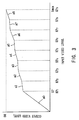
- a knee circuit processes an input video signal according to the fixed transfer function illustrated in Fig. 1. According to this function, output video level varies with input video level at a first constant rate until the single "knee point" is reached. The “knee point” is simply the input video level at which the transfer function changes. After the knee point, output video level varies with input video level at a second constant rate, wherein the second constant rate is less than the first constant rate.
- the frequency with which a particular input video level occurs is not necessarily proportional to the input video level.
- the distribution of input video levels may be generally concentrated around two particular input video signal levels.
- the y-axis represents the number of occurrences while the x-axis represents input video intensity level.
- the number of occurrences preferably refers to the number of imaging elements, e.g. pixels, which register a particular intensity or luminance level in a given input image.
- an object of the present invention is to provide video signal compression apparatus utilizing multiple compression ratios for compressing different input video levels differing amounts.
- Another object of the present invention is to provide video signal compression apparatus for allocating the output video signal according to the frequency with which a particular input video level occurs.
- a further object of the present invention is to provide video signal compression apparatus which adapts the allocation of the output video signal to the distribution of signal intensity or luminance of the input video signal.
- Still another object of the present invention is to provide video compression apparatus which allocates a greater amount of an output video signal to components of an input video signal which occur more often than other components of the input video signal.
- a video signal compression apparatus for compressing an input video signal having multiple signal levels to produce an output video signal having multiple signal level.
- a device receives the input video signal and an analyzing device analyzes the input video signal to determine the distribution of signal levels present in the input video signal.
- a signal compression device compresses the input video signal as a function of the distribution to produce the output video signal.
- a video signal compression apparatus for compressing an input video signal having multiple signal levels to produce an output video signal.
- a device receives the input video signal and a signal compression device compresses the input video signal as a function of the signal levels of the input video signal.
- the input video signal is compressed according to at least three different compression functions to produce the output video signal.
- a camera system includes an imaging device for acquiring an image signal having multiple luminance levels and a signal compression device for compressing the image signal as a function of the luminance levels such that the image signal is compressed according to at least three different compression functions to produce a video signal.
- a video compression apparatus analyzes an input video signal and configures itself to adjust the compression of different signal components of the input video signal in an effort to exploit particular characteristics of the input video signal.
- a representation of such an adaptive compression technique is provided in Fig. 3.
- Fig. 3 illustrates an example of a transform function in which output video level varies according to several different rates with respect to the input video level.
- video level refers to signal intensity, luminance, tone, power, strength or any similar characterization of a video signal.
- the output video signal can range between zero and DR, the maximum dynamic range of the signal.
- the piecewise linear transform function extends between an input video level of zero and I max , the maximum intensity level, and is comprised of nine line segments, each having its own constant slope a 0 , a 1 , a 2 , ... a 8 .
- knee points KP i and KP i+1 define a line segment having a slope of a i , i being an integer variable between one and k, the number of line segments.
- the line segment of slope a 0 extends between a given point on the output video level axis and KP 1 , also referred to simply as KP.
- Each of the slopes a i represents the particular amount of video signal compression to be applied to input video signals having levels in the range of KP i to KP i+1 .
- the transform function is depicted as an increasing function divided into nine segments, the invention is not limited to this specific example.
- the transform function may be comprised of any number of segments, each having its own slope which is different from that of immediately adjacent segments, i.e. a 0 , a 1 , ... a k .
- the transfer function may be entirely or partly decreasing, that is, one or more of the slopes a i may be negative.
- the dynamic range DR of the output video signal can be expressed as: KP + a 1 ⁇ I max -KP k + a 2 ⁇ I max -KP k + a 3 ⁇ I max -KP k + ...
- each slope a i of each segment, and consequently the degree to which the corresponding components of the input video signal are compressed, is allocated in direct proportion to the frequency with which the components of the input video signal fall within the range of levels KP i to KP i+1 .
- the appropriate amount of compression for each corresponding component of the input video signal can be obtained. In this manner, the dynamic range of the output video signal is allocated according to the signal level histogram of the input video signal.
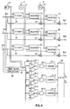
- FIG. 4 A knee circuit implementing the above-described method of allocating the output video signal is illustrated in Fig. 4.
- This knee circuit is comprised of knee-point memory 10; slope memory 11; intercept memory 12; multiple-comparator units 13, 18, and 23; slope selectors 14, 19, and 24; intercept selectors 15, 20, and 25; multipliers 16, 21, and 26; adders 17, 22, and 27; maximum value detector 28; comparators 29-1, 29-2,...29-(2k - 2); AND gates 30-1, 30-2,...30-(k - 1); counters 31-1, 31-2,...31-(k - 1); and CPU 32.
- maximum value detector 28 comparators 29-1,...29-(2k - 2), AND gates 30-1,...30-(k - 1), counters 31-1,...31-(k - 1), and CPU 32 operate together to determine the distribution of signal levels of the input video signal, e.g. a histogram of the signal, on a real time, frame-by-frame, field-by-field or like basis.
- the remainder of the knee circuit operates to process that input video signal or the next input video signal as a function of the histogram which has been determined.
- An input digital signal formed of three components R IN , G IN , and B IN , are supplied to maximum value detector 28.
- the detector passes the signal component having the greatest level to comparators 29-1,...29-(2k - 2) as signal M 1 .
- level refers to signal intensity, luminance, tone, power, strength or any similar characterization of a video signal.
- the maximum value detector may pass the signal component having the greatest average level over a period of time, or apply some other similar criteria in selecting the signal component to be passed.
- the maximum value detector 28 may be replaced by an adding circuit which combines the three components R IN , G IN , and B IN by straight addition, by a weighted combination such as ( 0.3R IN + 0.6G IN + 0.1B IN ) corresponding to a brightness signal, or by some other conventional RGB signal combining method and which supplies the three component combination to the comparators as signal M 1 .
- Knee-point memory 10 is preset with a predetermined number of signal level values corresponding to knee points KP i which will be used to divide the input signal into ranges of input signal levels. Knee-point memory 10 supplies individual knee point values to comparators 29-1,...29-(2k - 2). Since the exact number of knee points "k” will depend upon the particular application, the comparators, AND gates, and counters are illustrated as a repeating structure. In general, there will be (2k - 2) comparators 29-(i), (k - 1) AND gates 30-(i), and (k - 1) counters 31-(i).
- the comparators and the AND gates are configured to isolate specific ranges of signal levels of the M 1 signal supplied by maximum value detector 28.
- Comparators 29-1 and 29-2 supply a logic one output signal to AND gate 30-1 if M 1 falls between KP 1 and KP 2 .
- Comparators 29-3 and 29-4 supply a logic one output signal to AND gate 30-2 if M 1 falls between KP 2 and KP 3 .
- comparators 29-5 and 29-6 supply a logic one output signal to AND gate 30-3 if M 1 falls between KP 3 and KP 4 . Should M 1 fall outside a range defined by two knee points, one of the comparators will supply a logic zero output signal to the corresponding AND gate.
- AND gate 30-1 causes it to supply a logic one signal to the corresponding counter 31-1 causing it to increment its running count.
- Each of the counters 31-1,...31-(k - 1) counts the number of times signal M 1 contains a component within one of the given ranges of levels.
- the counters produce a histogram of signal M 1 . Following the end of signal M 1 or some subdivision thereof, such as the end of a scan line, a field, a frame, or the like, CPU 32 receives from each of the counters the current count stored therein. The counters are then reset.
- CPU 32 thus obtains the histogram of signal M 1 divided into ranges defined by the knee points KP i .
- CPU 32 calculates a slope a and an intercept b for each of the (k - 1) ranges and outputs these as signals A and B, respectively.
- Signal A loads slope memory 11 with each of the slopes a i while signal B loads intercept memory 12 with each of the intercepts b i .
- the three components R IN , G IN , and B IN are also supplied to each of multiple-comparator units 13, 18, and 23, respectively, and to each of multipliers 16, 21, and 26, respectively.
- Multiple-comparator unit 13 serves to categorize the levels of signal R IN as portions of the signal are input with respect to knee points KP i , e.g. unit 13 determines between which two knee points each portion of the input signal belongs.
- unit 13 can be configured in a manner similar to that of comparators 29-1,...29-(2k - 2) in conjunction with AND gates 30-1,...30-(k - 1).
- Comparator unit 13 supplies its categorization i to slope selector 14 and intercept selector 15.
- Slope selector 14 uses the quantity i to access the corresponding slope a i stored in slope memory 11 and supplies slope a i to multiplier 16.
- Intercept selector 15 uses the quantity i to access the corresponding intercept b i stored in intercept memory 12 and supplies intercept b i to adder 17.
- Multiplier 16 multiplies the particular portion of signal R IN by slope a i and supplies the product to adder 17.
- Adder 17 adds b i to this product to produce a sum which is output as output signal R OUT .
- output signals G OUT and B OUT are formed. According to this method, the dynamic range of the output signal is allocated to the corresponding input signal according to a histogram of the input signal.
- a charge-coupled device (CCD) camera system is comprised of a lens 41, CCD 42, amplifier 43, pre-compressor 44, analog-to-digital (A/D) converter 45, image enhancer 46, decompressor 47, knee circuit 48, gamma corrector 49, and black/white clipper 50.
- Lens 41 focusses incident light from an image upon CCD 42.
- CCD 42 develops video signal S1 representative of the incident light and supplies video signal S1 to amplifier 43.
- Amplifier 43 transmits an amplified video signal S1 to precompressor 44.
- Pre-compressor 44 is conventional devices for compressing and decompressing, respectively, the luminance portion of video signal S1.
- pre-compressor 44 may be a prior art knee circuit.
- Pre-compressor 44 preferably compresses the "high" luminance portion of video signal S1, which originally may be beyond the range of a/d converter 45.
- a/d converter 45 converts analog video signal S1 into digital video signal D1.
- Signal D1 is decompressed by decompressor 47 to reconstruct the luminance portion of video signal S1 in a digital format.
- Signal D1 is also processed by image enhancer 46 which preferably operates to "square off" abrupt variations in the incident light that are inherently filtered by CCD 42 and produces a detail signal.
- decompressor 47 decompresses the "high" luminance portion of signal D1 with an inverse of the method employed by pre-compressor 44.
- the decompressed signal is supplied to knee circuit 48 which compresses the signal according to the compression method of the present invention. Preferred construction and operation of knee circuit 48 have been described in connection with Fig. 4.
- Knee circuit 48 supplies the compressed signal to gamma circuit 49 for gamma correction.
- the gamma corrected signal is combined with the detail signal and the combined signal is supplied to black/white clipper 50.
- Black/white clipper 50 preferably "clips" the combined signal where it overextends either boundary of a given range of values, thus "clipping" the signal to the color black or the color white.
Landscapes
- Engineering & Computer Science (AREA)
- Multimedia (AREA)
- Signal Processing (AREA)
- Picture Signal Circuits (AREA)
- Testing, Inspecting, Measuring Of Stereoscopic Televisions And Televisions (AREA)
Applications Claiming Priority (3)
| Application Number | Priority Date | Filing Date | Title |
|---|---|---|---|
| JP33823494 | 1994-12-26 | ||
| JP338234/94 | 1994-12-26 | ||
| JP33823494A JP3444449B2 (ja) | 1994-12-26 | 1994-12-26 | 映像信号処理装置 |
Publications (3)
| Publication Number | Publication Date |
|---|---|
| EP0720358A2 true EP0720358A2 (fr) | 1996-07-03 |
| EP0720358A3 EP0720358A3 (fr) | 1998-04-01 |
| EP0720358B1 EP0720358B1 (fr) | 2002-04-03 |
Family
ID=18316197
Family Applications (1)
| Application Number | Title | Priority Date | Filing Date |
|---|---|---|---|
| EP95120141A Expired - Lifetime EP0720358B1 (fr) | 1994-12-26 | 1995-12-20 | Dispositif de compression d'un signal vidéo utilisant des degrés de compression multiples |
Country Status (6)
| Country | Link |
|---|---|
| US (1) | US6002796A (fr) |
| EP (1) | EP0720358B1 (fr) |
| JP (1) | JP3444449B2 (fr) |
| KR (1) | KR100382048B1 (fr) |
| CN (1) | CN1096187C (fr) |
| DE (1) | DE69526193T2 (fr) |
Cited By (1)
| Publication number | Priority date | Publication date | Assignee | Title |
|---|---|---|---|---|
| AT408286B (de) * | 1999-09-10 | 2001-10-25 | Siemens Ag Oesterreich | Verfahren zur unterdrückung von störrauschen in einem signalfeld |
Families Citing this family (10)
| Publication number | Priority date | Publication date | Assignee | Title |
|---|---|---|---|---|
| EP1152604A1 (fr) * | 2000-04-24 | 2001-11-07 | Pulnix America, Inc. | Réduction de l'éblouissement vidéo |
| US6606418B2 (en) * | 2001-01-16 | 2003-08-12 | International Business Machines Corporation | Enhanced compression of documents |
| JP4153715B2 (ja) * | 2002-04-08 | 2008-09-24 | 松下電器産業株式会社 | 映像信号処理装置及び映像信号処理方法 |
| JP4385841B2 (ja) * | 2004-04-22 | 2009-12-16 | ソニー株式会社 | 画像処理装置 |
| US7706440B2 (en) * | 2005-02-08 | 2010-04-27 | Hong Kong Applied Science And Technology Research Institute Co., Ltd. | Method for reducing bit rate requirements for encoding multimedia data |
| JP4759363B2 (ja) * | 2005-10-27 | 2011-08-31 | Hoya株式会社 | 画像信号処理ユニット |
| US7680328B2 (en) * | 2006-11-01 | 2010-03-16 | Mtekvision Co., Ltd. | Histogram generating device |
| JP4992507B2 (ja) * | 2007-03-28 | 2012-08-08 | ソニー株式会社 | 撮像装置、映像信号処理装置及び映像信号処理方法 |
| KR101442601B1 (ko) * | 2007-11-28 | 2014-09-19 | 삼성전자주식회사 | 파일의 타겟 압축율 결정방법 및 장치 |
| WO2016161637A1 (fr) | 2015-04-10 | 2016-10-13 | SZ DJI Technology Co., Ltd. | Procédé, appareil et système permettant d'assurer une couverture de communication à un véhicule aérien sans pilote |
Family Cites Families (7)
| Publication number | Priority date | Publication date | Assignee | Title |
|---|---|---|---|---|
| KR100202344B1 (ko) * | 1990-03-26 | 1999-06-15 | 이데이 노부유끼 | 자동니제어회로 |
| US5221963A (en) * | 1990-03-31 | 1993-06-22 | Minolta Camera Kabushiki Kaisha | Video camera having a video signal processing apparatus |
| DE69227492T2 (de) * | 1991-08-30 | 1999-04-08 | Matsushita Electric Industrial Co., Ltd., Kadoma, Osaka | Bildverarbeitungsgerät |
| US5339368A (en) * | 1991-11-21 | 1994-08-16 | Unisys Corporation | Document image compression system and method |
| JP3255677B2 (ja) * | 1992-01-14 | 2002-02-12 | 松下電器産業株式会社 | 自動階調補正回路と輝度制御方法 |
| EP0613294B1 (fr) * | 1993-02-24 | 1998-10-28 | Matsushita Electric Industrial Co., Ltd. | Dispositif de correction de la gradation et dispositif capteur d'images equipé d'un tel dispositif |
| US5633511A (en) * | 1995-12-22 | 1997-05-27 | Eastman Kodak Company | Automatic tone scale adjustment using image activity measures |
-
1994
- 1994-12-26 JP JP33823494A patent/JP3444449B2/ja not_active Expired - Lifetime
-
1995
- 1995-12-19 US US08/574,520 patent/US6002796A/en not_active Expired - Lifetime
- 1995-12-20 DE DE69526193T patent/DE69526193T2/de not_active Expired - Lifetime
- 1995-12-20 EP EP95120141A patent/EP0720358B1/fr not_active Expired - Lifetime
- 1995-12-21 KR KR1019950053443A patent/KR100382048B1/ko not_active Expired - Fee Related
- 1995-12-26 CN CN95120991A patent/CN1096187C/zh not_active Expired - Lifetime
Cited By (1)
| Publication number | Priority date | Publication date | Assignee | Title |
|---|---|---|---|---|
| AT408286B (de) * | 1999-09-10 | 2001-10-25 | Siemens Ag Oesterreich | Verfahren zur unterdrückung von störrauschen in einem signalfeld |
Also Published As
| Publication number | Publication date |
|---|---|
| EP0720358A3 (fr) | 1998-04-01 |
| KR100382048B1 (ko) | 2003-07-10 |
| CN1096187C (zh) | 2002-12-11 |
| DE69526193D1 (de) | 2002-05-08 |
| KR960028232A (ko) | 1996-07-22 |
| DE69526193T2 (de) | 2002-10-31 |
| US6002796A (en) | 1999-12-14 |
| EP0720358B1 (fr) | 2002-04-03 |
| JP3444449B2 (ja) | 2003-09-08 |
| CN1131372A (zh) | 1996-09-18 |
| JPH08181887A (ja) | 1996-07-12 |
Similar Documents
| Publication | Publication Date | Title |
|---|---|---|
| US5247366A (en) | Color wide dynamic range camera | |
| US7020353B1 (en) | Extended dynamic range imaging system and method | |
| EP0983683B1 (fr) | Procede et appareil permettant de mettre en oeuvre une amelioration d'images | |
| US5473373A (en) | Digital gamma correction system for low, medium and high intensity video signals, with linear and non-linear correction | |
| US8116563B2 (en) | Image processing device and method, recording medium, and program | |
| US6002796A (en) | Video signal compression apparatus utilizing multiple compression ratios | |
| EP0595299A2 (fr) | Méthode et appareil de prise d'image pour une plage dynamique étendue | |
| EP0784399A1 (fr) | Dispositif de prise de vues | |
| JP2000029449A (ja) | 画像デ―タ処理方法およびディスプレイシステム | |
| EP0823814B1 (fr) | Circuit de mixage d'images | |
| CN114223209B (zh) | Hdr图像传感器的自适应图像数据线性化 | |
| US6753910B1 (en) | Image processing apparatus and image processing method | |
| EP0457522B1 (fr) | Circuits de correction de gamma | |
| EP1352518B1 (fr) | Commande de sensibilite adptative, a base pixel par pixel, destinee a un systeme de production d'images numerique | |
| GB2281674A (en) | Digital image contrast conversion | |
| KR100193387B1 (ko) | 광전 변환된 영상신호를 위한 디지탈 신호변환방법 및 그 장치 | |
| US5883984A (en) | Method and apparatus for contrast enhancement of color images | |
| JP2000152033A (ja) | 画像処理装置及び画像処理方法 | |
| KR970060961A (ko) | 적분 룩크업 테이블을 이용한 적응형 감마 보정장치 | |
| US20030179299A1 (en) | Edge emphasizing circuit | |
| EP0363209A2 (fr) | Dispositif de prise d'image thermique | |
| US20140240547A1 (en) | System and method for creating an image with a wide dynamic range | |
| KR0142262B1 (ko) | 자동 고휘도 압축회로 | |
| KR100639155B1 (ko) | 영상 시스템의 동적 범위를 확장하기 위한 시스템 및 방법 | |
| IL104611A (en) | A color camcorder with a wide contrast range |
Legal Events
| Date | Code | Title | Description |
|---|---|---|---|
| PUAI | Public reference made under article 153(3) epc to a published international application that has entered the european phase |
Free format text: ORIGINAL CODE: 0009012 |
|
| AK | Designated contracting states |
Kind code of ref document: A2 Designated state(s): DE FR GB |
|
| PUAL | Search report despatched |
Free format text: ORIGINAL CODE: 0009013 |
|
| AK | Designated contracting states |
Kind code of ref document: A3 Designated state(s): DE FR GB |
|
| 17P | Request for examination filed |
Effective date: 19980902 |
|
| 17Q | First examination report despatched |
Effective date: 19991021 |
|
| GRAG | Despatch of communication of intention to grant |
Free format text: ORIGINAL CODE: EPIDOS AGRA |
|
| GRAG | Despatch of communication of intention to grant |
Free format text: ORIGINAL CODE: EPIDOS AGRA |
|
| GRAG | Despatch of communication of intention to grant |
Free format text: ORIGINAL CODE: EPIDOS AGRA |
|
| GRAH | Despatch of communication of intention to grant a patent |
Free format text: ORIGINAL CODE: EPIDOS IGRA |
|
| REG | Reference to a national code |
Ref country code: GB Ref legal event code: IF02 |
|
| GRAH | Despatch of communication of intention to grant a patent |
Free format text: ORIGINAL CODE: EPIDOS IGRA |
|
| GRAA | (expected) grant |
Free format text: ORIGINAL CODE: 0009210 |
|
| AK | Designated contracting states |
Kind code of ref document: B1 Designated state(s): DE FR GB |
|
| REF | Corresponds to: |
Ref document number: 69526193 Country of ref document: DE Date of ref document: 20020508 |
|
| ET | Fr: translation filed | ||
| PLBE | No opposition filed within time limit |
Free format text: ORIGINAL CODE: 0009261 |
|
| STAA | Information on the status of an ep patent application or granted ep patent |
Free format text: STATUS: NO OPPOSITION FILED WITHIN TIME LIMIT |
|
| 26N | No opposition filed |
Effective date: 20030106 |
|
| REG | Reference to a national code |
Ref country code: GB Ref legal event code: 746 Effective date: 20120703 |
|
| REG | Reference to a national code |
Ref country code: DE Ref legal event code: R084 Ref document number: 69526193 Country of ref document: DE Effective date: 20120614 |
|
| PGFP | Annual fee paid to national office [announced via postgrant information from national office to epo] |
Ref country code: GB Payment date: 20121220 Year of fee payment: 18 |
|
| PGFP | Annual fee paid to national office [announced via postgrant information from national office to epo] |
Ref country code: FR Payment date: 20130130 Year of fee payment: 18 |
|
| GBPC | Gb: european patent ceased through non-payment of renewal fee |
Effective date: 20131220 |
|
| REG | Reference to a national code |
Ref country code: FR Ref legal event code: ST Effective date: 20140829 |
|
| PG25 | Lapsed in a contracting state [announced via postgrant information from national office to epo] |
Ref country code: GB Free format text: LAPSE BECAUSE OF NON-PAYMENT OF DUE FEES Effective date: 20131220 Ref country code: FR Free format text: LAPSE BECAUSE OF NON-PAYMENT OF DUE FEES Effective date: 20131231 |
|
| PGFP | Annual fee paid to national office [announced via postgrant information from national office to epo] |
Ref country code: DE Payment date: 20141211 Year of fee payment: 20 |
|
| REG | Reference to a national code |
Ref country code: DE Ref legal event code: R071 Ref document number: 69526193 Country of ref document: DE |