EP0720544B2 - Systeme electronique de verrouillage des portes d'un vehicule a moteur - Google Patents
Systeme electronique de verrouillage des portes d'un vehicule a moteur Download PDFInfo
- Publication number
- EP0720544B2 EP0720544B2 EP94928278A EP94928278A EP0720544B2 EP 0720544 B2 EP0720544 B2 EP 0720544B2 EP 94928278 A EP94928278 A EP 94928278A EP 94928278 A EP94928278 A EP 94928278A EP 0720544 B2 EP0720544 B2 EP 0720544B2
- Authority
- EP
- European Patent Office
- Prior art keywords
- key
- locking
- signal
- processing device
- signal processing
- Prior art date
- Legal status (The legal status is an assumption and is not a legal conclusion. Google has not performed a legal analysis and makes no representation as to the accuracy of the status listed.)
- Expired - Lifetime
Links
Images






Classifications
-
- G—PHYSICS
- G07—CHECKING-DEVICES
- G07C—TIME OR ATTENDANCE REGISTERS; REGISTERING OR INDICATING THE WORKING OF MACHINES; GENERATING RANDOM NUMBERS; VOTING OR LOTTERY APPARATUS; ARRANGEMENTS, SYSTEMS OR APPARATUS FOR CHECKING NOT PROVIDED FOR ELSEWHERE
- G07C9/00—Individual registration on entry or exit
- G07C9/00174—Electronically operated locks; Circuits therefor; Nonmechanical keys therefor, e.g. passive or active electrical keys or other data carriers without mechanical keys
- G07C9/00944—Details of construction or manufacture
-
- B—PERFORMING OPERATIONS; TRANSPORTING
- B60—VEHICLES IN GENERAL
- B60R—VEHICLES, VEHICLE FITTINGS, OR VEHICLE PARTS, NOT OTHERWISE PROVIDED FOR
- B60R25/00—Fittings or systems for preventing or indicating unauthorised use or theft of vehicles
-
- B—PERFORMING OPERATIONS; TRANSPORTING
- B60—VEHICLES IN GENERAL
- B60R—VEHICLES, VEHICLE FITTINGS, OR VEHICLE PARTS, NOT OTHERWISE PROVIDED FOR
- B60R25/00—Fittings or systems for preventing or indicating unauthorised use or theft of vehicles
- B60R25/01—Fittings or systems for preventing or indicating unauthorised use or theft of vehicles operating on vehicle systems or fittings, e.g. on doors, seats or windscreens
- B60R25/02—Fittings or systems for preventing or indicating unauthorised use or theft of vehicles operating on vehicle systems or fittings, e.g. on doors, seats or windscreens operating on the steering mechanism
- B60R25/021—Fittings or systems for preventing or indicating unauthorised use or theft of vehicles operating on vehicle systems or fittings, e.g. on doors, seats or windscreens operating on the steering mechanism restraining movement of the steering column or steering wheel hub, e.g. restraining means controlled by ignition switch
-
- B—PERFORMING OPERATIONS; TRANSPORTING
- B60—VEHICLES IN GENERAL
- B60R—VEHICLES, VEHICLE FITTINGS, OR VEHICLE PARTS, NOT OTHERWISE PROVIDED FOR
- B60R25/00—Fittings or systems for preventing or indicating unauthorised use or theft of vehicles
- B60R25/01—Fittings or systems for preventing or indicating unauthorised use or theft of vehicles operating on vehicle systems or fittings, e.g. on doors, seats or windscreens
- B60R25/04—Fittings or systems for preventing or indicating unauthorised use or theft of vehicles operating on vehicle systems or fittings, e.g. on doors, seats or windscreens operating on the propulsion system, e.g. engine or drive motor
-
- B—PERFORMING OPERATIONS; TRANSPORTING
- B60—VEHICLES IN GENERAL
- B60R—VEHICLES, VEHICLE FITTINGS, OR VEHICLE PARTS, NOT OTHERWISE PROVIDED FOR
- B60R25/00—Fittings or systems for preventing or indicating unauthorised use or theft of vehicles
- B60R25/20—Means to switch the anti-theft system on or off
- B60R25/2063—Ignition switch geometry
-
- B—PERFORMING OPERATIONS; TRANSPORTING
- B60—VEHICLES IN GENERAL
- B60R—VEHICLES, VEHICLE FITTINGS, OR VEHICLE PARTS, NOT OTHERWISE PROVIDED FOR
- B60R25/00—Fittings or systems for preventing or indicating unauthorised use or theft of vehicles
- B60R25/40—Features of the power supply for the anti-theft system, e.g. anti-theft batteries, back-up power supply or means to save battery power
- B60R25/406—Power supply in the remote key
-
- E—FIXED CONSTRUCTIONS
- E05—LOCKS; KEYS; WINDOW OR DOOR FITTINGS; SAFES
- E05B—LOCKS; ACCESSORIES THEREFOR; HANDCUFFS
- E05B19/00—Keys; Accessories therefor
- E05B19/04—Construction of the bow or head of the key; Attaching the bow to the shank
- E05B19/046—Construction of the bow or head of the key; Attaching the bow to the shank the shank being slidingly mounted on the bow, e.g. for storage
-
- G—PHYSICS
- G07—CHECKING-DEVICES
- G07C—TIME OR ATTENDANCE REGISTERS; REGISTERING OR INDICATING THE WORKING OF MACHINES; GENERATING RANDOM NUMBERS; VOTING OR LOTTERY APPARATUS; ARRANGEMENTS, SYSTEMS OR APPARATUS FOR CHECKING NOT PROVIDED FOR ELSEWHERE
- G07C9/00—Individual registration on entry or exit
- G07C9/00174—Electronically operated locks; Circuits therefor; Nonmechanical keys therefor, e.g. passive or active electrical keys or other data carriers without mechanical keys
- G07C9/00309—Electronically operated locks; Circuits therefor; Nonmechanical keys therefor, e.g. passive or active electrical keys or other data carriers without mechanical keys operated with bidirectional data transmission between data carrier and locks
-
- G—PHYSICS
- G07—CHECKING-DEVICES
- G07C—TIME OR ATTENDANCE REGISTERS; REGISTERING OR INDICATING THE WORKING OF MACHINES; GENERATING RANDOM NUMBERS; VOTING OR LOTTERY APPARATUS; ARRANGEMENTS, SYSTEMS OR APPARATUS FOR CHECKING NOT PROVIDED FOR ELSEWHERE
- G07C9/00—Individual registration on entry or exit
- G07C9/00174—Electronically operated locks; Circuits therefor; Nonmechanical keys therefor, e.g. passive or active electrical keys or other data carriers without mechanical keys
- G07C9/00309—Electronically operated locks; Circuits therefor; Nonmechanical keys therefor, e.g. passive or active electrical keys or other data carriers without mechanical keys operated with bidirectional data transmission between data carrier and locks
- G07C2009/00507—Electronically operated locks; Circuits therefor; Nonmechanical keys therefor, e.g. passive or active electrical keys or other data carriers without mechanical keys operated with bidirectional data transmission between data carrier and locks keyless data carrier having more than one function
-
- G—PHYSICS
- G07—CHECKING-DEVICES
- G07C—TIME OR ATTENDANCE REGISTERS; REGISTERING OR INDICATING THE WORKING OF MACHINES; GENERATING RANDOM NUMBERS; VOTING OR LOTTERY APPARATUS; ARRANGEMENTS, SYSTEMS OR APPARATUS FOR CHECKING NOT PROVIDED FOR ELSEWHERE
- G07C9/00—Individual registration on entry or exit
- G07C9/00174—Electronically operated locks; Circuits therefor; Nonmechanical keys therefor, e.g. passive or active electrical keys or other data carriers without mechanical keys
- G07C2009/00579—Power supply for the keyless data carrier
- G07C2009/00603—Power supply for the keyless data carrier by power transmission from lock
-
- G—PHYSICS
- G07—CHECKING-DEVICES
- G07C—TIME OR ATTENDANCE REGISTERS; REGISTERING OR INDICATING THE WORKING OF MACHINES; GENERATING RANDOM NUMBERS; VOTING OR LOTTERY APPARATUS; ARRANGEMENTS, SYSTEMS OR APPARATUS FOR CHECKING NOT PROVIDED FOR ELSEWHERE
- G07C9/00—Individual registration on entry or exit
- G07C9/00174—Electronically operated locks; Circuits therefor; Nonmechanical keys therefor, e.g. passive or active electrical keys or other data carriers without mechanical keys
- G07C2009/00579—Power supply for the keyless data carrier
- G07C2009/00603—Power supply for the keyless data carrier by power transmission from lock
- G07C2009/00611—Power supply for the keyless data carrier by power transmission from lock by using inductive transmission
-
- G—PHYSICS
- G07—CHECKING-DEVICES
- G07C—TIME OR ATTENDANCE REGISTERS; REGISTERING OR INDICATING THE WORKING OF MACHINES; GENERATING RANDOM NUMBERS; VOTING OR LOTTERY APPARATUS; ARRANGEMENTS, SYSTEMS OR APPARATUS FOR CHECKING NOT PROVIDED FOR ELSEWHERE
- G07C9/00—Individual registration on entry or exit
- G07C9/00174—Electronically operated locks; Circuits therefor; Nonmechanical keys therefor, e.g. passive or active electrical keys or other data carriers without mechanical keys
- G07C2009/00753—Electronically operated locks; Circuits therefor; Nonmechanical keys therefor, e.g. passive or active electrical keys or other data carriers without mechanical keys operated by active electrical keys
- G07C2009/00769—Electronically operated locks; Circuits therefor; Nonmechanical keys therefor, e.g. passive or active electrical keys or other data carriers without mechanical keys operated by active electrical keys with data transmission performed by wireless means
-
- G—PHYSICS
- G07—CHECKING-DEVICES
- G07C—TIME OR ATTENDANCE REGISTERS; REGISTERING OR INDICATING THE WORKING OF MACHINES; GENERATING RANDOM NUMBERS; VOTING OR LOTTERY APPARATUS; ARRANGEMENTS, SYSTEMS OR APPARATUS FOR CHECKING NOT PROVIDED FOR ELSEWHERE
- G07C9/00—Individual registration on entry or exit
- G07C9/00174—Electronically operated locks; Circuits therefor; Nonmechanical keys therefor, e.g. passive or active electrical keys or other data carriers without mechanical keys
- G07C2009/00753—Electronically operated locks; Circuits therefor; Nonmechanical keys therefor, e.g. passive or active electrical keys or other data carriers without mechanical keys operated by active electrical keys
- G07C2009/00769—Electronically operated locks; Circuits therefor; Nonmechanical keys therefor, e.g. passive or active electrical keys or other data carriers without mechanical keys operated by active electrical keys with data transmission performed by wireless means
- G07C2009/00785—Electronically operated locks; Circuits therefor; Nonmechanical keys therefor, e.g. passive or active electrical keys or other data carriers without mechanical keys operated by active electrical keys with data transmission performed by wireless means by light
Definitions
- the invention relates to an electronic door locking system.
- Such door locking systems are used for locking and Unlocking the doors of a motor vehicle via a Central locking system. If necessary, with the electronic key of the door locking system also actuated the ignition lock of the motor vehicle become.
- DE-OS 34 36 761 and DE-OS 32 25 754 is a door locking system for a motor vehicle known that from a to the intended Operating electronics containing key and a receiver that is more central Place is arranged in the motor vehicle.
- the key sends a coded operating signal wirelessly to the recipient.
- In the motor vehicle are means for Decoding of the coded operating signal provided, so that a positive evaluation of the operating signal the central locking system for locking or Unlocked the car doors actuated.
- the well-known electronic key continues to serve as an ignition key for the ignition lock of the motor vehicle. Is the electronic key in the ignition lock introduced, so is another coded Operating signal from the electronic key to the Ignition switch lock transferable. With successful decoding this operating signal is the commissioning made an operating unit of the motor vehicle.
- the disadvantage is that the electronic key too its function requires an energy source which, according to a certain period of use can be exhausted. In such a case, the key is no longer functional. An actuation of the central locking can then not take place, so that also in itself authorized users no longer have access to his Motor vehicle has.
- EP-A-0 536 430 there is an electronic one Door locking system described in which the energy source is reloadable in the key.
- To supply the Key with reload energy is in one in the door of the motor vehicle control unit for actuation the central locking a transmission arrangement for the transfer of the reloading energy by means of energy transport Waves arranged on the key.
- the key has a receiving arrangement for the reloading energy and an energy converter Conversion of this reloading energy into storage energy for the energy source in the key.
- the reloading energy is then always from the sending arrangement sent out if one delivered by the key Start signal is received.
- FR-A-2 674 895 is an electronic one Known door locking system for motor vehicles, where the key is not its own energy source has. Is in the car door of the motor vehicle a first transmitter / receiver with a relative Antenna and in the handle of the key is a second transmitter / receiver with antenna. Will the door handle operated by the user in the car door, so is about an electrical switch the first transmitter / receiver switched on and a first code from the first transmitter / receiver in the car door at second Transmitter / receiver transmitted in the key as an RF signal. This RF signal becomes energy in the key to supply the second transmitter / receiver won and the first code evaluated. With help the energy gained then becomes a second Code from the second transmitter / receiver in the key transmit the first transmitter / receiver in the car door. If both codes are evaluated positively the central locking in the car door operated.
- the invention has for its object a door locking system for a motor vehicle with an improved To provide functional and theft security, which is particularly simple, preferably the ease of use for the user should be improved.
- Embodiments of the invention are the subject of subclaims.
- the signal processing device containing the receiver can be particularly advantageous instead arrange the previous locking cylinder in the door handle, where the display of the respective closed state for the user with differently colored LEDs can be done.
- the door locking system is based on a wireless transmission of coded operating signals, advantageously a transmission by means of optical signals, for example infrared signals, or can be used by means of RF signals.
- the closing state can also be visualized Display device on the key particularly easy and inexpensive thanks to a red and a green Realize LED.
- the red LED signals the user a lock and the green one LED unlocking the car doors.
- the door locking system can be combined with other components integrate into a bus system on the motor vehicle. This results despite great ease of use a low cabling effort for the user.
- the door locking system can be easily Way to a bus system located in the motor vehicle connect in such a way that a Connection to the ignition lock is established.
- a side element with an effective area 360 degrees.
- the signals can be easily Way around in any position of the key the motor vehicle received or sent as well as from or to the signal processing device in the motor vehicle to get redirected.
- An electromagnetic lock in the locking arrangement the locking system can be particularly train advantageously as a rocker, the Locking rocker by means of a locking hook Locking arrangement engages behind.
- an electromagnet can be used for the unlocked second Condition the locking rocker out of engagement with the locking member bring.
- Another, permanent excitation owning holding magnets can Locking rocker can be held in the second state.
- Monitoring the state changes of the electromagnetic Locking can be done by capturing the inductive voltage or current change perform in the electromagnet.
- the locking arrangement in which the electromagnetic Lock engages can by the actuation mechanism for the car doors, the trunk lid o. Like. Be formed.
- This actuation mechanism can one with a return spring, rotatable stored locking body with a space for Inclusion of a stationary on the frame of the car door Have bolts, which due to the force of Return spring caused rotation of the locking body for Release of the bolt by means of a main catch of the locking body attacking the first paragraph of a Internal transmission member is lockable.
- the internal transmission link is by an internal operating lever can be disengaged from the main catch.
- the outer transmission link is a further variant can also be formed in two parts by the locking member is arranged on a locking pin, the locking pin under the action of a compression spring in the direction loaded on the external transmission member with a force is.
- the advantages achieved with the invention exist in particular in that the functional safety of the Key is increased.
- the key is largely maintenance-free.
- the energy supply of the Key can be sent directly from the recipient Signal processing device from with which even when the battery is exhausted the intended use of the Key is still possible. So can a replacement key even be designed without a battery.
- it can be based on the usual mechanical Replacement key and if necessary hidden place of the motor vehicle mechanical lock dispensed for an emergency opening which is accompanied by considerable cost savings.
- Another benefit is the improvement of Theft security. Listening to the key an unauthorized recipient can be prevented by transmitting the coded operating signal by approaching the signal processing device in the car door instead of using the remote control he follows. If the remote control is operated, so can be sent an operating signal that contains another code that is not identical to that of the one transmitted by rimpedement Operating signal is. This can cause only one door opening possible with the remote control is while tap-proof transmission the operating signal by approximating other functions of the motor vehicle can be activated, for example approval for commissioning at the ignition lock. In practice, the key is very copy-proof, which effectively prevents unauthorized door opening is.
- Still further advantages achieved with the invention are that the operation of the door locking system is simplified for the user. This can as soon as you press the remote control see the closed state. At a The remote control can be operated incorrectly immediately press again. This can be advantageously Design the locking system so that the user this from a spatial sphere of activity round can be operated remotely. The ease of use for the user is so increased Nevertheless, there is no increased effort necessary because only one receiving and / or transmitting element sufficient. This also allows bidirectional Communication between key and Signal processing device on the motor vehicle with realize minimal effort, which also Increases operational security and theft security.
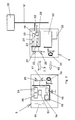
- Door locking system 1 shown is for a motor vehicle determines and consists of an electronic Key 2, the one for the intended Use electronics 14 includes, and one Receiver.
- the receiver is in a signal processing device 6 included in the car door 12 of the Motor vehicle is arranged.
- the key 2 swaps with the receiver in the signal processing device 6 a coded operating signal 7 when approaching the key 2 to the car door 12.
- With the signal processing device 6 stands over lines 18 which possibly also contain a preamplifier electronics 19 in the motor vehicle in connection.
- the electronics 19, which may be can be located in the car door 12 contains means for Decoding the coded operating signal 7. At positive evaluation of the operating signal 7 in the electronics 19, i.e.
- Control unit 20 which is connected via lines 18 'to the electronics 19 is connected, for locking or unlocking the car doors 12 operated.
- the control unit 20 can it is, for example, a central locking system act.
- An alarm system can also be used at the same time put in or out of operation on the motor vehicle become.
- the key 2 of the door locking system 1 can also for remote control operation of the control unit 20 up to a certain maximum distance from the Serve motor vehicle.
- the electronics become the remote control 14 of the key 2 from one in the key 2 battery 30 supplied.
- a button is pressed 10 on the key 2 becomes a coded operating signal 8 sent unidirectionally, where appropriate to a code different from the operating signal 7 can act.
- the operating signal 8 is in turn from the signal processing device 6 on the car door 12 received and evaluated in the electronics 19. is the code is OK, the control unit 20 causes one Locking or unlocking the car doors 12.
- the operating signal for the remote control 8 bidirectional between the key 2 and the Signal processing device 6 are exchanged, which, however, involves more effort is.
- the Ignition lock 3 is connected via connecting lines 4 with an associated operating unit 5 in connection.
- an operating unit 5 for example to the electronic engine control, a Act immobilizer of the motor vehicle or the like. through the in a receptacle 11 of the ignition lock 3 inserted key 2, the operating unit 5th after exchanging at least one coded operating signal 9 between the key 2 and the ignition lock 3 and its positive evaluation in operation be taken.
- the actual arrangement of the door locking system 1 in the motor vehicle is closer in a first embodiment 2 can be seen from FIG.
- a signal processing device 6 arranged in the two front car doors 12 of the motor vehicle.
- the electronics 19 is in the door control unit 20, which is in the respective front Car door 12 is located, integrated. It can just as well Electronics 19 also in the signal processing device 6 can be integrated, as shown in Fig. 3.
- the control units 20 of the car doors 12 control motors 35 for Locking and unlocking the respective car door 12.
- the trunk area Control unit 20 for the trunk lid 37 is arranged.
- the trunk lid 37 also has one Signal processing device 6.
- other lockable parts on the motor vehicle for example, the fuel filler cap or the like, such Signal processing device 6 and an associated Control unit 20 included.
- a bistable electromagnetic barrier Locking arrangement 84 can be provided, as in 2 by way of example using the rear car doors 12 is shown. The formation of this locking arrangement 84 will be explained in more detail.
- the signal processing devices 6, the control units 20 and the motors 35 or locking arrangements 84 in a bus system 39 are integrated, with 39 a connection to the ignition starter lock 3, the operating unit 5 etc. is made.
- the key 2 and the signal processing device 6 transmitted operating signal 7 can then besides the locking and unlocking of the Car doors 12 still have other functions in the motor vehicle Can be triggered via the bus system 39, for example the car alarm system can be in and out Operation can be set.
- the door locking system 1 by means of bidirectional Communication that explains in more detail key 2 by approaching the car door 12 is operated simultaneously with the unlocking of the door locking system 1 via the bus system 39 Commissioning of the operating unit 5 to release.
- At least one can be set by means of the bus system 39 Achieve easier wiring in the motor vehicle.
- the Bus system 39 can, for example, be the one from the CAN bus known from automotive electronics, as for example in the literature reference Philips: CAN products for universal fields of application, January 1992 is described. Of course there is also a other bus system can be used equally.
- the detailed design of the electronics of the door locking system 1 according to the first embodiment is shown as a basic block diagram in Fig. 3.
- the Signal processing device 6 has means for inductive non-contact transmission of energy the key 2 on. These funds consist of one Induction coil 31 in the signal processing device 6 is arranged and by one with the wiring system supply line 33 related Power transmission electronics 32 is fed.
- in the Key 2 is an electromagnetic transmission coil 34 arranged so that when the Key 2 to the corresponding car door 12 Energy transmission 40 begins by the induction coil 31 and the electromagnetic transmission coil 34 cooperate accordingly.
- the electronics 14 of the key 2 can be activated and operated as intended.
- the electronics 14 by the signal processing device 6 energized so that the im Key 2 existing battery 30 only is required when operating the remote control.
- the battery 30 has a long life Lifespan, so that changing the Battery 30 is very rarely required.
- At least the door locking system 1 is too then still operable if the battery 30 fails, so that no mechanical lock, for example at a hidden point in the motor vehicle, for emergency opening with a mechanical key, as before usual, must be provided.
- inductive energy transmission 40 can also be another energy transfer, for example an optical energy transmission is provided his. Then, instead of the induction coil 31 an optical one in the signal processing device 6 Sending element arranged, for example as LED is formed. Located in the key 2 itself instead of the electromagnetic transmission coil 34 an optical receiving element. The Transmitting element emits light or infrared rays when the key 2 approaches the signal processing device 6 added by the receiving element and converted into electrical energy become. This energy is used for the intended purpose Key operation 2. This saves energy because the energy transmission electronics 32 only in Operation is when it is actually needed.
- Electronics 14 includes a first one Operating signal transmitter 15, the optoelectronic Transmitters, for example infrared transmitters with an infrared transmitter diode 17, can be formed. Further contains the electronics 14 a first operating signal encoder 16, which in turn with the first operating signal transmitter 15 communicates.
- the signal processing device 6 also has electronics 19. Electronics 19 contains a first optical receiver, for example infrared receiver with associated Infrared receiver diode 22, trained operating signal receiver 21 and one with the first operating signal receiver 21 related first Operating signal decoder 23. This is a first Code 55 (see also FIG.
- the first operating signal encoder 16 in the first operating signal encoder 16 can be generated and from the first operating signal transmitter 15 of the key 2 at first Operating signal receiver 21 in the signal processing device 6 when the key 2 approaches the signal processing device 6 can be transmitted, the first code 55 in the first operating signal decoder 23 of the electronics 19 decrypted and evaluated becomes. It can then with a first training of the Door locking system 1 after a positive evaluation of the first code 55 the locking or unlocking of the Car doors 12 and the trunk lid 37 made so that the first code 55 is the operating signal 7 shown in FIG. 1a.
- the door locking system 1 now a second one each, as an optoelectronic receiver, for example infrared receiver with associated Infrared receiver diode 25, trained operating signal receiver 24 and a second operating signal decoder 26 in key 2 and a second, as optoelectronic transmitter, for example infrared transmitter with associated infrared transmitter diode 28, trained Operating signal transmitter 27 and second Operating signal encoder 29 in the signal processing device 6 may be arranged.
- the second code 56 then acts with first code 55 in a bidirectional communication together, i.e. it is a positive evaluation of both the second Codes 56 as well as the first code 55 necessary to the locking and unlocking of the car doors 12 and the trunk lid 37 to enable. It is in this case with the operating signal shown in Fig. 1a 7 around the interacting first and second Code 55, 56. Through bidirectional communication will further improve security against theft of the door locking system 1 achieved.
- the door locking system 1 works as described even when the key 2 approaches the Trunk by the operating signal 7 between the Key 2 and the signal processing device 6 in the trunk lid 37 is replaced. It is further to emphasize that a selective Ver or Unlocking can be realized. By approximating the Key 2 to the corresponding car door 12 or the trunk can after successful transfer of the operating signal 7, if desired, only the respective one Car door 12 or the trunk lid 37 locked or unlocked become.
- the function of the remote control already mentioned the central locking system is also from the first Operating signal transmitter 15 exercised by this Pressing the button 10 one of the first operating signal encoder 16 encrypted code as operating signal 8, the code of the operating signal 8 possibly different from the first or second Code 55, 56 of the operating signal 7 can be about the infrared transmitter diode 17 emits unidirectionally
- This operating signal 8 is from the first operating signal receiver 21 in the signal processing device 6 on one of the car doors 12 or possibly the trunk lid 37 received and in the electronics 19 evaluated. After a positive evaluation then the locking or unlocking of the car doors 12 and if necessary, the other lockable parts on Motor vehicle causes.
- the electronics 14 in the key 2 is powered by the battery 30 so that the remote control even from a distance from the Motor vehicle is functional, at which none Energy transmission 40 from the respective signal processing device 6 uses key 2.
- the electronics are responsible for the function of the remote control 14 supplied from the battery 30. Um now a premature discharge of the battery 30 to prevent, the electronics 14 in key 2 has one electronic circuit for lowering the quiescent current on a vanishing quiescent current, with which in the rest position of the key 2 none Energy is taken from the battery.
- the electronic circuit is closer in Fig. 14 shown and has a microprocessor 119, which also still serve for other tasks in electronics 14 can, for example as the first operating signal encoder 16 etc.
- a current flows from the Battery 30 through circuit 120 to the base of the Transistor 124 and turns it on. This will again the transistor 125 turned on, the Circuit 121 opens so that the supply voltage input 127 of the microprocessor 119 on the Voltage of the battery 30 is.
- the microprocessor 119 activates, the microprocessor 119 now activates an output 128 which in turn acts on the base of transistor 124. This keeps the supply voltage above Circuit 121 turned on even when button 10 is released again.
- the supply voltage remains switched on until the activities for the Remote control are handled. Then the Microprocessor 119 the output 128 inactive, which the Transistors 124, 125 are blocked, which in turn the circuit 121 is turned off. So that is the microprocessor 119 is switched off by the battery 30 and the quiescent current is also switched off.
- the key 2 is sent to the signal processing device 6 approximates, so as already sets described an energy transfer 40 as here for example with the electromagnetic transmission coil 34 is shown.
- This transferred energy will via the circuit 122 to the microprocessor 119 as Supply voltage supplied.
- it will Presence of energy transmission 40 over the Circuit 123 detected and a corresponding one Signal via input 129 to the microprocessor 119 passed on.
- This signal switches on and maintaining another exit 130, which in turn turns on transistor 126 becomes.
- This blocks transistor 124 so that the circuit 121 remains locked even if the Key 10 is pressed simultaneously. So that the transferred Energy from circuit 122 does not exceed Circuit 121 act on the battery 30, thus effectively protecting them from destruction is.
- the lowering circuit of the quiescent current causes energy for the Operation of the transmitter with the remote control only after Actuation of the button 10 from the battery 30 is removed. Otherwise, the However, no energy is taken from key 2.
- the next step in the case of energy transmission is from the signal processing device 6 the battery 30 also completely switched off.
- the signal processing device 6 as in Fig. 2 can be seen, two by the user outside of Illuminants visible to the motor vehicle, such as light-emitting diodes 43, 44, arranged.
- the light emitting diodes 43, 44 show the closed state of the door locking system 1 on.
- the two light-emitting diodes 43, 44 can be different be colored, for example the light emitting diode 43 red and the LED 44 green.
- the light emitting diode 43 then signals that the car door 12 or the trunk lid 37 is locked and the light diode 44 that the car door 12 and the trunk lid 37 unlocked is.
- the coded operating signal is transmitted 7 to the signal processing device 6 as optical signal, for example infrared signal.
- optical signal for example infrared signal.
- RF signal transmission such as further embodiment schematically in Fig. 4 in a block diagram explaining the principle is shown is.
- the key 2 ' has a transmit and Receive modules and the coding or decoding modules containing electronics 14 with which the electromagnetic transmission coil 34 in connection stands.
- the signal processing device 6 ' there is a corresponding induction coil 31, with which the send and receive blocks as well as the coding and decoding modules containing electronics 19 is connected.
- the line 18 ' is the electronics 19 in the signal processing device 6 'again with the control unit 20 in connection.
- the electromagnetic transmission coil 34 in the manner of a transponder and an induction coil 31 can in turn be a coded Operating signal 7 between the key 2 'and the Signal processing device 6 ', namely an electromagnetic Signal as RF signal, on inductive Paths when the key 2 'approaches the corresponding one Car door 12 or the trunk lid 37 be replaced.
- the transmitted Energy for operating the electronics 14 is used. This Energy becomes a signal field, controlled by the electronics 19 superimposed, which may be the one at bidirectional communication from the signal processing device 6 'second code 56 to be transmitted (See Fig.
- the signal field is also from the electromagnetic transmission coil 34 of the Key 2 'received.
- the electronics 14 determined from the signal field the second code 56 and decrypted this.
- the electronics 14 further dampens the certain part of the signal field accordingly the first code 55 to be transmitted (see FIG. 9).
- This attenuation of the signal field is caused by the electronics 19 of the signal processing device 6 'registered and from this the transmitted first code 55 is determined and decrypted.
- the second code 55, 56 is in turn the locking and unlocking of the car doors 12 and the Trunk lid 37 performed.
- FIG. 5 shows the arrangement of the signal processing devices 6 'in the car doors 12 and the trunk lid 37 of the motor vehicle and the Training of the key 2 'according to this further Embodiment shown in more detail, the arrangement is carried out essentially analogously to FIG. 2.
- the consisting of master key 41 'or replacement key 42' Key 2 has an electromagnetic one Transmission coil 34 that with the induction coil 31 in the signal processing device 6 'for energy and Operating signal transmission when approaching the corresponding car door 12 or the trunk lid 37 cooperates.
- the master key 41 ' additionally has a remote control function he further an infrared transmitter diode 17 with associated Operating signal transmitter and a battery 30.
- the signal processing device has 6 'with an additional infrared receiving diode 22 associated operating signal receiver.
- the central locking additional optical operating signal between the Master key 41 'and the signal processing device 6 'interchangeable.
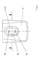
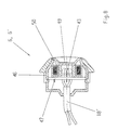
- the signal processing device 6, 6 ' is preferred in the operating handle, i.e. that in FIG. 1 shown door handle 13 in the car door 12 or the handle for the trunk lid 37 housed. Especially The signal processing device can advantageously be used 6, 6 'instead of the conventional mechanical Place the lock cylinder in the operating handle. A such training for the door handle 13 is closer to 6 to 8 can be seen.
- the signal processing device 6, 6 ' has one Housing 46 in which the induction coil 31 on a Printed circuit board 47 is arranged.
- the induction coil 31 can also a ferrite core 50 shown in FIG. 8.
- the circuit board 47 also serves as a carrier for the here Electronics 19 not shown (see FIG. 3).
- the of the Circuit board 47 outgoing lines 18 'to the control unit 20 are through a rear opening 48 on Housing 46 passed through.
- On the circuit board 47 are the two the respective closed state of the door locking system 1 indicating LEDs 43, 44 by means of a transparent Housing cover 49 are covered so that they protected and still outside the vehicle are visible to the user.
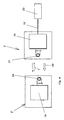
- this is remotely controllable Door locking system 1 schematically in Fig. 1b shown.
- a key 10 on key 2 exchanges the key 2 with the example near the Interior mirror 60 or the dashboard in the center Motor vehicle arranged signal processing device 6 an encoded operating signal 8.
- the control unit 20 can be, for example, a known one Act central locking.
- the signal processing device 6 with the control units 20 in the Car doors 12 is integrated into a bus system 39, a connection also via the bus system 39 to the ignition lock 3, the operating unit 5, etc. manufactured is. If the evaluation between the Key 2 and the signal processing device 6 transmitted for remote control of the door locking system 1 Operating signal 8 can then except the Ver and Unlocking the car doors 12 still other functions can be triggered in the motor vehicle via the bus system 39 be, for example, is conceivable at the same time as the Unlocking the door locking system 1 via the bus system 39 the commissioning of the operating unit 5 release or with the locking of the door locking system 1 the commissioning of the operating unit 5 to lock.
- the operating signal 8 can be unidirectional or bidirectional between the key 2 and the signal processing device 6 can be exchanged.
- a preferred embodiment of the bidirectional communication consists in identifying an individual identifier in two codes of the operating signal 8. These Design of the bidirectional communication should following will be explained in more detail with reference to FIGS. 3 and 9.
- the electronics 14 contains a data memory 51, which is, for example, an EEPROM memory can act.
- this data memory 51 is a unique identifier for the respective motor vehicle stored as an individual identifier. With this individual identifier can it be, for example, from Unique number assigned to vehicle manufacturers act.
- the same individual identifier is also in a data memory 52 in the signal processing device 6 saved.
- the operating signal encoder 16, 29 and operating signal decoders 23, 26 operate according to a defined algorithm. This algorithm can, if necessary, in the data memory 51, 52 filed or by an appropriate electronic Circuit be realized.
- Next is in the signal processing device 6 also a random number generator 53rd
- an identification signal 54 is sent by the key 2 and received by the signal processing device 6.
- the transmission of the second code 56 is triggered.
- a random number generator 53 is used Random number determined as a key figure and in the data memory 52 of the signal processing device 6 is stored. If necessary, it is also sufficient if the random number each time the operating unit is started up 5 newly determined and stored in the data memory 52. From this key figure located in the data memory 52 is in the second operating signal encoder 29 of the signal processing device 6 based on the specified Algorithm formed a code, which is the second code 56 by means of the second operating signal transmitter 27 to the Key 2 is transferred.
- This from the key 2 recorded by means of the second operating signal receiver 24 second code 56 is by means of the second Operating signal decoder 26 based on the specified Algorithm decoded into a determined key figure ..
- This determined key figure as well as that in the data memory 51 of the key 2 stored individual identifier are now to form a first code 55 in first operating signal encoder 16 of the key 2 used with another algorithm. simultaneously the determined key figure in the data memory 51 saved.
- the first code 55 is then from first operating signal transmitter 15 to the first Operating signal receiver 21 in the signal processing device 6 transferred. After that, the first one Code 55 in the first operating signal decoder 23 of the Signal processing device 6 according to the further Algorithm decrypted, from which another determined Key figure and another identified individual identifier result.
- a comparison is then made the further individual identifier determined and others determined key figure with that in data memory 52 the signal processing device 6 stored Individual identifier and key figure. This comparison goes positive, i.e. it is the right one Individual identification and key figure, so the Signal processing device 6, control unit 20 controlled accordingly for locking or unlocking.
- Both Bulbs are different colored light-emitting diodes, for example by a red one and green light-emitting diode 58, 59 for a closed state in each case.
- the lighting up the red LED 58 then signals the user the locking and lighting up of the green ones Light-emitting diode 59 unlocking the car doors 12. In particular the user immediately sees whether the transfer of the operating signal 8 was successful or whether if necessary, press this button repeat.
- LEDs 58, 59 also an LCD display or the like Find display device use.
- the signal processing device 6 is an all-round receiver and transmitter with a spatial Effective area of approximately 360 degrees.
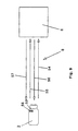
- the guide element 61 is used for recording and if necessary to deliver the signals as well forwarding them from or to the means for receiving or send.
- the guide element 61 can also on elsewhere centrally in the motor vehicle, for example be attached to the dashboard.
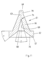
- the closer formation of such a guide element 61 for optical signals such as infrared signals 10 and 11 can be seen.
- the body of the lead element 61 has on one side, namely the lower one Side, the desired spatial scope covering round surface 62, which is for receiving serves or delivery of the optical signals and at the other, upper side a light guide section 63, the with a transition surface 64 for the optical signals to an optoelectric converter element 65 of the Signal processing device 6 is configured.
- the round surface 62 is on the light guide section 63 via a conical connection surface 66 arranged.
- the body of the guide element 61 is made made of optically transparent plastic, such as plexiglass. Preferably, the body can be made in one piece Manufacture injection molding process.
- the optoelectric converter element 65 can be the infrared receiving diode shown in FIG. 3 22 and / or infrared transmitter diode 28 of the Act signal processing device 6. 10 is an infrared receiving diode as the optoelectric converter element 65 to see.
- the connecting surface 66 consists of a funnel-shaped Formation, this formation being one in FIG. 11 designated funnel opening angle ⁇ from about 30 to Can have 60 degrees.
- the round surface 62 consists of an annular rim 67 which is at the funnel opening 68 tapered at the transition 70 to the inside of the funnel 69 of the connecting surface 66 extends.
- This Bevel at transition 70 can also be in Fig. 11 designated angle ⁇ of about 30 to 60 degrees have.
- the light guide section 63 is from the top the connecting surface 66 is formed at the funnel outlet 71, which can merge into a cylindrical part 78, as can be seen in Fig. 11.
- the inside mirror 60 has a Bracket 72, on which the guide element 61 is fastened, as shown in Fig. 10 in more detail.
- the light guide section 63 protrudes through an opening 73 in the holder 72.
- a Closing element 74 arranged that a circuit board 80 wears.
- the optoelectric Transducer element 65 On the circuit board 80 is the optoelectric Transducer element 65 arranged such that its active surface 75 of transition surface 64 in the opening 73 is opposite.
- an optically transparent, rotationally symmetrical Display element 79 which is similar to the guide element 61 is formed.
- This display element 79 is in turn with a illuminants 82 located on the printed circuit board 80 in Connection that in two different colors, for example can shine in red and green. If the car doors 12 are unlocked, it lights up Bulb 82 in green and when locked in red Color briefly. This gives the user additional a visual check for display on key 2 about the closed state assumed.
- This Display element 79 is also outside the motor vehicle visible due to the rotational symmetry.
- the display element 79 can also simultaneously as Guiding element for an infrared transmitter diode serve optoelectric converter element 83, wherein an electrical one in the optoelectric converter element 83 Signal from the signal processing device 6 converted into a failing infrared signal 77 becomes. This falling infrared signal 77 is also recorded by the display element 79 and due the rotationally symmetrical geometry of the Display element 79 fanned out into a beam. This bundle of rays then becomes the exit of the display element 79, where the infrared signal 77 the display element 79 with a spatial area of effect of about 360 degrees and then in Key 2 can be received again. Of course can also guide element 61 for the same Purpose.
- the signals are transmitted, such as the first code 55, second code 56, identification signal 54 and status signal 57, as an optical Signal, namely as an infrared signal.
- an optical Signal namely as an infrared signal.
- RF signal transmission as shown in the Fig. 4 has already been explained, or another wireless Signal transmission may be provided.
- the locking arrangement already shown schematically in FIG. 2 84 is preferably to the actuating mechanism for the car door 12, the is operated via an outside or inside door handle, as well as the actuation mechanism for further lockable and unlockable parts on the motor vehicle, as for the trunk lid 37, the fuel cap o.
- the control device 20 for controlling these actuation mechanisms, the central in the motor vehicle or decentralized in the car door 12 or the respective to be operated Part can be arranged, causes the Locking arrangement 84 for manual actuation over the door handle 13 on the car door 12 in the manner of a Central locking is locked or released.
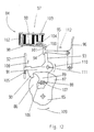
- a first embodiment for the locking arrangement 84 in the car door 12 is closer to Fig. 12 too see.
- the locking arrangement 84 has a rotatable one stored locking body 85 with a main catch 86 and Vorraste 87. In the space 89 between the The main catch 86 and the catch 87 engage on the frame the car door 12 fixed bolt 88. In the in Fig. 12 position of the locking body 85 is the Car door 12 thus closed. To open the Car door 12 together with the locking body 85 in the direction of Arrow 107 and to close in the direction of the arrow 106 moves. Opening the car door 12 is in this position of the locking body 85 prevented by the main catch 86.
- bistable electromagnetic barrier 97 in a first Condition such that the movement of the outer transmission member 95 is prevented, with which ultimately the Locking body 85 cannot be rotated to release the bolt 88 is and the car door 12 for manual operation is locked via the outer operating lever 96.
- a State change of the bistable electromagnetic Lock 97 causes and the electromagnetic lock 97 out of engagement with the latch assembly 84 brought, whereby the locking assembly 84 released is and ultimately the car door 12 on the outside operating lever 96 can be opened. So that is through the electromagnetic lock 97 in one first state the locking arrangement 84 for manual operation locked and in a second State the latch assembly 84 for manual Operation via the external operating lever 96 released.
- the electromagnetic lock 97 is a locking rocker 98 trained by an electromagnet 99 can be actuated.
- the locking rocker 98 engages behind first state by means of a locking hook 100 an extension of the finger 94 on the external transmission link 95 formed locking member 101 of the locking arrangement 84.
- the locking rocker 98 is located under the force of a spring 102 so that the In the first state, the lock cannot be removed from the outside , the force of the spring 102 is also violent Overcoming the locking hook 100 via the external operating lever 96 prevented. To the transition from The electromagnet 99 is the first in the second state excitable, this attracts the locking rocker 98.
- the locking hook 100 is disengaged from the Brought locking member 101, as in Fig. 12 with thinner Lines is indicated, and thereby the locking arrangement 84 unlocked.
- the electromagnetic Lock 97 an additional one, with the electromagnet 99 preferably in a common magnetic circuit has holding magnet 103 located.
- the Holding magnet 103 works with its permanent excitation to a corresponding one located on the locking rocker 98 Permanent magnets 104 such a that even if the electromagnet 99 fails, the locking rocker 98 is held in the second state.
- the second state i.e. with released locking arrangement 84, is then advantageously none permanent excitation of the electromagnet 99 necessary. It is enough for the transition from the first to the second Condition a short-term overexcitation of the Make electromagnet 99. Conversely in the transition from the second to the first state, thus when locking the locking arrangement 84, a overcoming the attraction of the holding magnet 103 Counterexcitation of the electromagnet 99 made.
- the respective state of electromagnetic Lock 97 can by display means 43, 44 (see also Fig. 6), which can be viewed from the outside of the motor vehicle can, for example, by in the door handle of the car door 12 are arranged to be signaled, as already is explained above.
- To monitor the State changes of the locking arrangement 84 can capture the inductive voltage or Current change of the electromagnet 99 through the Electronics 19 take place.
- With motorized or pneumatic Means on the car door 12 can also be achieve automatic door opening. After successful Transmission of the operating signal 7, 8 is an unlock the car door on the latch assembly 84 as described. Then at the same time via the control unit 20 the automatic door opening by a certain opening gap to increase comfort triggered for the user.
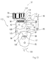
- a locking arrangement 113 with two parts trained external transmission link is another Embodiment seen in Fig. 13. Are there same parts with the same reference numerals as in Fig. Designated 12.
- the locking member 116 to which the locking hook 100 on the locking rocker 98 acts, is located together with the finger 117, which engages with the second Approach 93 is on one of the external transmission link 114 separate locking pin 115.
- the locking pin 115 is in the direction of the force of a compression spring 118 loaded on the external transmission member 114. in the first state of the electromagnetic lock 97, i.e. when the locking arrangement 113 is blocked the locking hook 100 on the locking member 116 a Movement of the locking pin 115. This allows the Car door 12 does not have the outer operating lever 96 to open.
- the electromagnetic lock 97 is located in the second state, in which the locking arrangement 113 is released, there is the locking hook 100 out of engagement with the locking member 116.
- the invention is not described and described illustrated embodiments limited. she Rather, it also includes all professional training within the scope of the claims. If a recipient for the Remote control at a central point in the motor vehicle, for example as described on the inside mirror, and further signal processing devices containing a receiver in the car doors, the trunk lid etc. be arranged. In this case, the Central locking controlled from the central point be while the other recipients mainly for selective locking and unlocking when approaching to the corresponding car door or the Trunk lid or the like can be used.
- the described formation of the locking arrangement can not only be used in electronic door locking systems with electronic keys but equally can also be used with locking systems that are locked and unlocked a mechanical key become.
Landscapes
- Engineering & Computer Science (AREA)
- Mechanical Engineering (AREA)
- Physics & Mathematics (AREA)
- General Physics & Mathematics (AREA)
- Computer Networks & Wireless Communication (AREA)
- Manufacturing & Machinery (AREA)
- Lock And Its Accessories (AREA)
Claims (21)
- Système électronique de fermeture de porte sur un véhicule automobile comportant :a) au moins un dispositif de traitement de signal (6,6') comportant un récepteur (21), sur une porte (12),b) une clé (2,2') comprenant une électronique (14) qui sert au fonctionnement conforme aux prescriptions et qui échange avec le récepteur un signal de fonctionnement codé (7,8),c) des moyens (23) pour décoder le signal de fonctionnement codé (7,8) de sorte que, par une évaluation positive du signal de fonctionnement (7,8), un appareil de commande (20) pour modifier l'état de fermeture, correspondant à un verrouillage ou un déverrouillage des portes (12), peut être actionné,d) des moyens (31,34) pour la transmission sans contact de l'énergie du dispositif de traitement de signal (6,6') à la clé (2,2') de sorte que la transmission d'énergie (40) est déclenchée, lors de l'approche de la clé (2,2') de la porte correspondante (12), et l'électronique (14) de la clé (2,2') est activée par la réception d'énergie et est commandée de façon conforme aux prescriptions,e) une batterie (30) située dans la clé (2,2'), de l'énergie pour le fonctionnement de l'électronique (14) pouvant être extraite de la batterie (30) lors de l'actionnement de la commande à distance sur la clé (2,2') de sorte qu'un signal de fonctionnement codé (8) pour la commande à distance de l'appareil de commande (20) pour le verrouillage et le déverrouillage des portes (12) est transmis de la clé (2,2') au dispositif de traitement de signal (6,6') à une distance du dispositif de traitement de signal (6,6') telle qu'aucune transmission d'énergie à la clé (2,2') n'est encore déclenchée, etf) des moyens (123) pour détecter la transmission d'énergie (40) du dispositif de traitement de signal (6,6'), ces moyens (123) provoquant, lors de la présence d'une transmission d'énergie (40), dans une zone proche :d'une part, une mise hors service de l'alimentation en énergie à partir de la batterie (30) etd'autre part, le blocage de l'action de l'énergie à partir de la transmission d'énergie (40) sur la batterie (30).
- Système électronique de fermeture de porte selon la revendication 1,
caractérisé en ce que l'on agence un autre dispositif de traitement de signal (6) dans au moins une autre partie susceptible d'être fermée du véhicule, en particulier dans le capot (37) du coffre, un verrouillage ou déverrouillage sélectif de la partie correspondante susceptible d'être fermée du véhicule étant réalisé lors de l'approche de la clé (2) de la partie susceptible d'être fermée, et en ce que le dispositif de traitement de signal (6,6') peut être situé dans la poignée d'actionnement de la partie correspondante susceptible d'être fermée, au lieu du cylindre mécanique de fermeture. - Système électronique de fermeture de porte selon l'une des revendications 1 ou 2,
caractérisé en ce que dans le dispositif de traitement de signal (6) est agencée une bobine d'induction (31) et dans la clé (2) une bobine de transmission électromagnétique (34), comme moyens pour la transmission inductive d'énergie, la bobine d'induction (31) et la bobine de transmission électromagnétique (34) coopérant, lors de l'approche de la clé (2) des portes correspondantes (12), pour la transmission d'énergie inductive (40), ou en ce que dans le dispositif de traitement de signal est agencé un élément d'émission optique, par exemple une diode luminescente, et dans la clé un élément de réception optique, par exemple un élément photosensible, comme moyens pour la transmission optique d'énergie, les éléments d'émission et de réception coopérant, lors de l'approche de la clé des portes correspondantes, pour la transmission d'énergie optique, et en ce que le signal de fonctionnement (7,8) peut être échangé sous forme d'un signal électromagnétique, comme un signal de haute fréquence et/ou un signal optique, entre la clé (2,2') et le dispositif de traitement de signal (6,6'). - Système électronique de fermeture de porte selon la revendication 3,
caractérisé en ce que le signal de fonctionnement (7) peut être échangé par l'intermédiaire des moyens pour la transmission d'énergie inductive, un champ de signal étant superposé à l'énergie transmise du dispositif de traitement de signal (6'), champ de signal contenant le cas échéant le signal de fonctionnement devant être transmis par le dispositif de traitement de signal (6'), et une partie de ce champ de signal étant atténuée par la clé (2') en correspondance au signal de fonctionnement (7) devant être transmis par la clé (2'). - Système électronique de fermeture de porte selon l'une des revendications 1 à 4,
caractérisé en ce que des émetteurs de signaux, par exemple des diodes luminescentes (43,44) de couleurs différentes, sont agencés dans le dispositif de traitement de signal (6), pour indiquer l'état de fermeture. - Système électronique de fermeture de porte selon l'une des revendications 1 à 5,
caractérisé en ce que la clé (2,2') comprend un circuit électronique pour réduire le courant de repos de la batterie (30), en particulier à un courant de repos infiniment petit, le circuit prélevant de l'énergie pour le fonctionnement de l'émetteur dans la batterie (30) uniquement après l'actionnement de la commande à distance sur la clé (2,2') et débranchant la batterie (30) lors de la transmission d'énergie (40) du dispositif de traitement de signal (6,6'). - Système électronique de fermeture de porte selon l'une des revendications 1 à 6,
caractérisé en ce qu'un signal d'état supplémentaire (57) codant l'état de fermeture correspondant de l'appareil de commande (20), engendré après l'évaluation du signal de fonctionnement (7,8), peut être transmis d'un dispositif de traitement de signal (6) contenant le récepteur vers la clé (2), l'information contenue dans le code du signal d'état (57) pouvant être représentée sur un dispositif d'indication agencé sur la clé (2) et pouvant être constitué d'une diode luminescente rouge (58) pour le verrouillage et d'une diode luminescente verte (59) pour le déverrouillage des portes (12). - Système électronique de fermeture de porte selon l'une des revendications 1 à 7,
caractérisé en ce que pour échanger le signal de fonctionnement (7,8) entre la clé (2) et le dispositif de traitement de signal (6), on agence au moins à chaque fois un moyen pour coder et émettre, ainsi que pour recevoir et décoder le signal de fonctionnement (7,8) dans la clé (2) et dans le dispositif de traitement de signal (6), et en ce que de préférence le signal de fonctionnement (7,8) est constitué d'un deuxième code (56) transmis du dispositif de traitement de signal (6) à la clé (2) et d'un premier code (55) transmis ensuite de la clé (2) au dispositif de traitement de signal (6), les deux codes (55,56) coopérant dans une communication bidirectionnelle, en ce que tout d'abord le deuxième code (56) est transmis et après son décodage positif la transmission du premier code (55) peut être déclenchée, et en particulier la transmission du deuxième code (56) étant déclenchée après la transmission d'un signal de reconnaissance (54), engendrée par l'opérateur sur un organe d'actionnement (10) de la clé (2), de la clé (2) au dispositif de traitement de signal (6). - Système électronique de fermeture de porte selon la revendication 8,
caractérisé en ce que le deuxième code (56) codé à partir d'un algorithme comporte, comme nombre caractéristique, un nombre aléatoire engendré au moyen d'un générateur de nombre aléatoire (53), en ce que le premier code (55) codé à partir d'un algorithme comporte une reconnaissance individuelle stockée aussi bien dans la clé (2) que dans le dispositif de traitement de signal (6), respectivement dans une mémoire de données (51,52), pour laquelle il peut s'agir d'un nombre non équivoque, et en ce que le premier code (55) codé à partir d'un algorithme comporte de plus le nombre caractéristique transmis dans le deuxième code (56). - Système électronique de fermeture de porte selon l'une des revendications 1 à 9,
caractérisé en ce que le dispositif de traitement de signal (6) est raccordé, par l'intermédiaire de l'appareil de commande (20) pour le verrouillage ou le déverrouillage des portes (12), à un système à bus (39) dans le véhicule automobile, le système à bus (39) réalisant de préférence une liaison vers une serrure d'amorçage (3) et un agrégat de fonctionnement (5), comme une électronique de moteur, un arrêt de voie de roulement ou analogue, de sorte que lors d'une évaluation positive du signal de fonctionnement (7,8), d'autres fonctions peuvent être déclenchées simultanément dans le véhicule automobile, par exemple la libération de l'agrégat de fonctionnement (5) pour la mise en fonctionnement, la mise en ou hors service de l'installation d'alarme ou analogue. - Système électronique de fermeture de porte selon l'une des revendications 1 à 10,
caractérisé en ce que les signaux, à savoir les premier et deuxième codes (55,56), le signal d'état (57) et le cas échéant le signal de reconnaissance (54) sont constitués d'un signal électromagnétique, comme un signal à haute fréquence, un signal infrarouge ou analogue, un élément de commande (61) servant à l'échange et à la transmission des signaux étant relié de préférence au dispositif de traitement de signal (6), avec en particulier une zone d'action spatiale d'à peu près 360 degrés, et de préférence également l'élément de commande (61) étant agencé centralement dans le véhicule automobile, par exemple sur le rétroviseur (60) ou sur le tableau de bord. - Elément de commande pour des signaux optiques, comme des signaux infrarouges, pour un système électronique de fermeture de porte (1) selon la revendication 11, comportant un corps,
caractérisé en ce que le corps réalisé en particulier par un procédé de moulage par injection est constitué d'une matière synthétique optiquement transparente, comme du plexiglas, et comporte, sur une face, une face ronde (62) recouvrant une zone d'action spatiale, en particulier d'environ 360 degrés, et servant à la réception ou à l'émission des signaux optiques (76,77) et, sur l'autre face, un tronçon de guide de lumière (63) qui est formé, par une face de transmission (64) pour les signaux optiques (76,77), vers un élément transducteur optoélectrique (65) du dispositif de traitement de signal (6), la face ronde (62) étant agencée sur le tronçon de guide de lumière (63) par l'intermédiaire d'une face de liaison (66) réalisée le cas échéant de façon conique. - Elément de commande selon la revendication 12,
caractérisé en ce que le corps présente une symétrie de rotation, la face de liaison (66) étant réalisée de préférence sous forme conique avec en particulier un angle d'ouverture conique (α) d'à peu près 30 à 60 degrés, la face ronde (62) étant réalisée sous forme d'un bord (67) annulaire qui, biseauté à l'ouverture conique (68), passe dans la face interne conique (69) de la face de liaison (66) avec en particulier un angle (β) d'à peu près 30 à 60 degrés, et 60 degrés, et le tronçon de guide de lumière (63) étant formé par la pointe sur la sortie conique (71) de la face de liaison (66), la pointe passant le cas échéant dans une partie cylindrique agencée à la sortie conique (71) de la face de liaison (66). - Elément de commande selon l'une des revendications 12 ou 13,
caractérisé en ce que le corps est agencé dans un élément de maintien (72) comportant une ouverture (73) pour le tronçon de guide de lumière (63), l'élément transducteur optoélectrique (65) étant situé dans l'élément de maintien (72), le cas échéant sur une plaque de conduction (80), de sorte que sa face active (75) est opposée à la face de passage (64) du tronçon de guide de lumière (63), et un élément d'indication (79) optiquement transparent et symétrique en rotation étant agencé de préférence dans l'élément de maintien (72), pour l'état de fermeture engendré, et étant en liaison avec un moyen luminescent correspondant (82) et/ou un élément transducteur optoélectrique (83). - Système de fermeture de porte selon l'une des revendications 1 à 11, comportant une dispositif de verrouillage (84,113) qui peut être commandé par une clé (2) réalisée de préférence sous forme d'une clé électronique, par l'intermédiaire d'un dispositif de commande (20), et qui peut être bloqué ou débloqué pour l'actionnement manuel au moyen de la clé (2),
caractérisé en ce que la clé (2) provoque un modification de l'état d'un élément de blocage (97) électromagnétique et bistable, qui dans un premier état bloque le dispositif de verrouillage (84,113) pour l'actionnement manuel et dans un second état libère le dispositif de verrouillage (84,113) pour l'actionnement manuel, la modification d'état de l'élément de blocage électromagnétique (97) étant provoquée en particulier lors d'une évaluation positive d'un signal de fonctionnement transmis (7,8) par l'intermédiaire du dispositif de commande (20). - Système de fermeture de porte selon la revendication 15,
caractérisé en ce que l'élément de blocage électromagnétique (97) est constitué d'une bascule de blocage (98) et d'un électroaimant (99) pour l'actionnement de la bascule de blocage (98), la bascule de blocage (98) agissant dans le premier état au moyen d'un crochet d'arrêt (100) dans un élément blocant (101,116) du dispositif de verrouillage (84,113), en particulier sous l'action de la force d'un ressort (102), et pouvant être amenée hors action avec l'élément blocant (101,116), pour le passage dans le second état, par l'excitation de l'électroaimant (99). - Système de fermeture de porte selon la revendication 16,
caractérisé en ce que l'élément de blocage électromagnétique (97) comporte un aimant adhérent (103) supplémentaire, se trouvant avec l'électroaimant (99) de préférence sur un circuit magnétique commun, et agissant par son excitation permanente sur la bascule de blocage (98) de sorte que, lorsque l'électroaimant (99) n'est pas excité, la bascule de blocage (98) peut être maintenue dans le second état, et de préférence pour le passage du premier au second état une excitation à courte durée étant réalisée, et pour le passage du second au premier état une contre-excitation de l'électroaimant (99), dépassant la force d'attraction de l'aimant adhérent (103) étant réalisée. - Système de fermeture de porte selon l'une des revendications 16 ou 17,
caractérisé en ce que la surveillance des modifications d'état de l'élément blocant électromagnétique (97) est réalisée par la détection de la modification inductive de la tension ou du courant dans l'électroaimant (99), l'état correspondant de l'élément blocant électromagnétique (97) étant signalé de préférence par des moyens d'indication visibles, par exemple des moyens luminescents (43,44) de couleurs différentes. - Système de fermeture de porte selon l'une des revendications 15 à 18,
caractérisé en ce qu'il s'agit pour le dispositif de verrouillage (84,113), dans lequel agit l'élément blocant électromagnétique (97), de la mécanique d'actionnement dans la poignée (13) de la porte (12) et/ou de la mécanique d'actionnement pour d'autres parties susceptibles d'être verrouillées et déverrouillées du véhicule, comme le capot du coffre (37), le couvercle du réservoir ou analogue, l'appareil de commande (20) pour déclencher la mécanique d'actionnement étant agencé centralement dans le véhicule automobile ou de façon décentralisée dans la porte (12) ou dans la partie à actionner. - Système de fermeture de porte selon la revendication 19,
caractérisé en ce que le dispositif de verrouillage (84,113) comporte un corps d'arrêt (85) muni d'un ressort de retour, monté de façon rotative et comprenant un espace intermédiaire (89) pour recevoir un tourillon (88) fixé sur le cadre de la porte (12), la rotation du corps d'arrêt (85) engendrée par le ressort de retour pouvant être arrêtée au moyen d'une première saillie (90) pouvant être amenée en action avec le corps d'arrêt (85), sur l'élément de transmission interne (91), en ce qu'un levier d'actionnement interne (92) est en liaison active avec l'élément de transmission interne (91), et en ce qu'un élément de transmission externe (95) qui est en liaison active avec un levier d'actionnement externe (96) agit sur une seconde saille (93) de l'élément de transmission interne (91), l'élément de blocage électromagnétique (97) bloquant l'élément de transmission externe (95) sur un élément blocant (101,116) dans le premier état, et le libérant dans le second état de sorte qu'au moyen du levier d'actionnement interne (92), ainsi que dans le second état de l'élément de blocage électromagnétique (97), de plus au moyen du levier d'actionnement externe (96), l'élément de transmission interne (91) peut être mis hors action avec le corps d'arrêt (85), pour libérer le tourillon (88). - Système de fermeture de porte selon la revendication 20,
caractérisé en ce que l'élément de transmission externe (114) est réalisé en deux parties, dans lequel est agencé l'élément blocant (116) sur un tourillon de blocage (115), le tourillon de blocage (115) étant contraint par une force, sous l'action d'un ressort de pression (118), en direction de l'élément de transmission externe (114).
Applications Claiming Priority (11)
| Application Number | Priority Date | Filing Date | Title |
|---|---|---|---|
| DE4333505 | 1993-10-01 | ||
| DE4333505 | 1993-10-01 | ||
| DE9320270U DE9320270U1 (de) | 1993-10-01 | 1993-11-26 | Schließmanagement |
| DE9320270U | 1993-11-26 | ||
| DE4404496 | 1994-02-12 | ||
| DE4404496 | 1994-02-12 | ||
| DE4416242 | 1994-05-07 | ||
| DE4416242 | 1994-05-07 | ||
| DE4421496 | 1994-06-20 | ||
| DE19944421496 DE4421496B4 (de) | 1993-10-01 | 1994-06-20 | Elektronisches Türschließsystem an einem Kraftfahrzeug |
| PCT/DE1994/001152 WO1995009747A2 (fr) | 1993-10-01 | 1994-09-30 | Systeme electronique de verrouillage des portes d'un vehicule a moteur |
Publications (3)
| Publication Number | Publication Date |
|---|---|
| EP0720544A1 EP0720544A1 (fr) | 1996-07-10 |
| EP0720544B1 EP0720544B1 (fr) | 1997-03-05 |
| EP0720544B2 true EP0720544B2 (fr) | 2002-08-28 |
Family
ID=27511706
Family Applications (1)
| Application Number | Title | Priority Date | Filing Date |
|---|---|---|---|
| EP94928278A Expired - Lifetime EP0720544B2 (fr) | 1993-10-01 | 1994-09-30 | Systeme electronique de verrouillage des portes d'un vehicule a moteur |
Country Status (3)
| Country | Link |
|---|---|
| EP (1) | EP0720544B2 (fr) |
| ES (1) | ES2101572T5 (fr) |
| WO (1) | WO1995009747A2 (fr) |
Families Citing this family (6)
| Publication number | Priority date | Publication date | Assignee | Title |
|---|---|---|---|---|
| FR2731190B1 (fr) * | 1995-03-02 | 1997-05-30 | Sellem Albert | Dispositif antivol pour vehicule automobile |
| FR2792753B1 (fr) * | 1999-04-20 | 2001-11-02 | Valeo Securite Habitacle | Systeme d'autorisation de demarrage pour un vehicule automobile |
| JP3987570B1 (ja) * | 2004-04-26 | 2007-10-10 | ムン,ギュ−ヨン | 分解することなく設置及び除去が可能なドアロック装置 |
| US20050280501A1 (en) * | 2004-06-21 | 2005-12-22 | Honeywell International, Inc. | Automotive latch and RF system interfacing |
| TWI633028B (zh) | 2015-04-22 | 2018-08-21 | 鴻海精密工業股份有限公司 | 車輛鑰匙系統及其使用方法 |
| DE102018002157A1 (de) | 2018-03-16 | 2019-09-19 | Zf Active Safety Gmbh | Vorrichtung und Verfahren zur verschlüsselten Übertragung eines digitalen Steuersignals von einem Kraftfahrzeugschlüssel an ein Kraftfahrzeug |
Family Cites Families (12)
| Publication number | Priority date | Publication date | Assignee | Title |
|---|---|---|---|---|
| EP0153613B1 (fr) * | 1984-02-23 | 1989-04-26 | Identitech Corporation | Système d'entrée passif sans clé |
| DE3536377A1 (de) * | 1985-10-11 | 1987-04-16 | Bayerische Motoren Werke Ag | Sicherheitseinrichtung fuer kraftfahrzeuge |
| US4887312A (en) * | 1987-09-14 | 1989-12-12 | Siemens Aktiengesellschaft | Method and apparatus for transmission of optical data between two electrically separated transmitting receiving units |
| IT1223678B (it) * | 1988-07-11 | 1990-09-29 | Mario Turatti | Sistema identificatore elettronico particolarmente per il comando di bloccasterzo serrature di portiere ed altre applicazioni automobilistiche |
| JP3143123B2 (ja) * | 1990-11-06 | 2001-03-07 | マイクロン・テクノロジー・インコーポレイテッド | デュアルモード電子識別システム |
| FR2674895A1 (fr) * | 1991-04-03 | 1992-10-09 | Vachette Sa | Dispositif de commande de la decondamnation d'une serrure, notamment pour portiere de vehicule automobile . |
| WO1993002897A1 (fr) * | 1991-07-30 | 1993-02-18 | General Motors-Holden's Automotive Limited | Systeme de securite pour vehicule |
| JP2901394B2 (ja) * | 1991-08-09 | 1999-06-07 | アルプス電気株式会社 | 遠隔操作装置 |
| DE4226053C2 (de) * | 1991-08-09 | 1994-12-01 | Alps Electric Co Ltd | Fernbedienungseinrichtung für eine KFZ-Schließanlage |
| EP0536430B1 (fr) * | 1991-09-30 | 1997-02-19 | Siemens Aktiengesellschaft | Procédé pour desservir une télécommande en énergie p.e. pour un système de verrouillage pour automobile |
| GB2265482B (en) * | 1992-03-28 | 1995-07-26 | Pektron Ltd | Improvements in data transmission |
| DE9307176U1 (de) * | 1993-05-07 | 1993-07-22 | Hartmann, Friedrich, 24253 Probsteierhagen | Elektronische Diebstahlsicherung für Personenkraftwagen |
-
1994
- 1994-09-30 WO PCT/DE1994/001152 patent/WO1995009747A2/fr not_active Ceased
- 1994-09-30 ES ES94928278T patent/ES2101572T5/es not_active Expired - Lifetime
- 1994-09-30 EP EP94928278A patent/EP0720544B2/fr not_active Expired - Lifetime
Also Published As
| Publication number | Publication date |
|---|---|
| WO1995009747A2 (fr) | 1995-04-13 |
| ES2101572T3 (es) | 1997-07-01 |
| EP0720544A1 (fr) | 1996-07-10 |
| ES2101572T5 (es) | 2003-03-01 |
| WO1995009747A3 (fr) | 1995-06-29 |
| EP0720544B1 (fr) | 1997-03-05 |
Similar Documents
| Publication | Publication Date | Title |
|---|---|---|
| DE4421496B4 (de) | Elektronisches Türschließsystem an einem Kraftfahrzeug | |
| DE3737468C2 (fr) | ||
| DE4434587B4 (de) | Elektronisches Zündstartschloßsystem an einem Kraftfahrzeug | |
| DE3880496T2 (de) | Von einer batterie betriebenes tuerschloss sowie verfahren. | |
| EP1327043B1 (fr) | Systeme de fermeture electronique | |
| DE4409559C2 (de) | Schlüssel für Schließsystem | |
| EP0809743B1 (fr) | Cle electronique | |
| DE69107218T2 (de) | Elektromechanisches schloss und schlüssel hierfür. | |
| DE4340260A1 (de) | Schließsystem, insbesondre für Kraftfahrzeuge | |
| DE19520211A1 (de) | Elektronische Verriegelungsanordnung für ein Schloßsystem | |
| DE3306863C2 (de) | Schloßsystem für Kraftfahrzeuge, insbesondere Lenkschloßsystem | |
| DE4228233A1 (de) | Fernsteuerbares Schloß, insbesondere für Kraftfahrzeugtüren | |
| EP3434850B1 (fr) | Serrure électronique pour deux roues | |
| DE4434571A1 (de) | Elektronisches Türschließsystem an einem Kraftfahrzeug | |
| DE3421540A1 (de) | Schliesssystem mit einem batteriebetriebenen infrarot-handsender | |
| EP0542944B1 (fr) | Serrure a ame de cylindre motorisee | |
| EP0720544B2 (fr) | Systeme electronique de verrouillage des portes d'un vehicule a moteur | |
| DE202013005022U1 (de) | Kraftfahrzeugtür | |
| DE3442356A1 (de) | Zentralverriegelungsanlage fuer ein kraftfahrzeug | |
| DE9320270U1 (de) | Schließmanagement | |
| EP1029756A2 (fr) | Système de serrure d'allumage électronique pour un véhicule à moteur | |
| DE4434612B4 (de) | Schließsystem, insbesondere für Kraftfahrzeug | |
| DE10225368C1 (de) | Schließzylinder mit kontaktloser Übertragung eines Signals | |
| DE102004056987B4 (de) | Schließvorrichtung und Schließanlage, umfassend wenigstens eine Schließvorrichtung | |
| EP0913547B1 (fr) | Systéme de verrouillage, en particulier pour véhicules à moteur |
Legal Events
| Date | Code | Title | Description |
|---|---|---|---|
| PUAI | Public reference made under article 153(3) epc to a published international application that has entered the european phase |
Free format text: ORIGINAL CODE: 0009012 |
|
| 17P | Request for examination filed |
Effective date: 19960329 |
|
| AK | Designated contracting states |
Kind code of ref document: A1 Designated state(s): DE ES FR GB IT |
|
| GRAG | Despatch of communication of intention to grant |
Free format text: ORIGINAL CODE: EPIDOS AGRA |
|
| GRAH | Despatch of communication of intention to grant a patent |
Free format text: ORIGINAL CODE: EPIDOS IGRA |
|
| 17Q | First examination report despatched |
Effective date: 19960801 |
|
| GRAH | Despatch of communication of intention to grant a patent |
Free format text: ORIGINAL CODE: EPIDOS IGRA |
|
| GRAA | (expected) grant |
Free format text: ORIGINAL CODE: 0009210 |
|
| AK | Designated contracting states |
Kind code of ref document: B1 Designated state(s): DE ES FR GB IT |
|
| REF | Corresponds to: |
Ref document number: 59401986 Country of ref document: DE Date of ref document: 19970410 |
|
| GBT | Gb: translation of ep patent filed (gb section 77(6)(a)/1977) |
Effective date: 19970506 |
|
| REG | Reference to a national code |
Ref country code: ES Ref legal event code: FG2A Ref document number: 2101572 Country of ref document: ES Kind code of ref document: T3 |
|
| ET | Fr: translation filed | ||
| PLBQ | Unpublished change to opponent data |
Free format text: ORIGINAL CODE: EPIDOS OPPO |
|
| PLBI | Opposition filed |
Free format text: ORIGINAL CODE: 0009260 |
|
| PLBF | Reply of patent proprietor to notice(s) of opposition |
Free format text: ORIGINAL CODE: EPIDOS OBSO |
|
| 26 | Opposition filed |
Opponent name: F + G MEGAMOS SICHERHEITSELEKTRONIK GMBH Effective date: 19971205 Opponent name: PHILIPS PATENTVERWALTUNG GMBH Effective date: 19971205 |
|
| PLBF | Reply of patent proprietor to notice(s) of opposition |
Free format text: ORIGINAL CODE: EPIDOS OBSO |
|
| PLBF | Reply of patent proprietor to notice(s) of opposition |
Free format text: ORIGINAL CODE: EPIDOS OBSO |
|
| PLAW | Interlocutory decision in opposition |
Free format text: ORIGINAL CODE: EPIDOS IDOP |
|
| APAC | Appeal dossier modified |
Free format text: ORIGINAL CODE: EPIDOS NOAPO |
|
| APAE | Appeal reference modified |
Free format text: ORIGINAL CODE: EPIDOS REFNO |
|
| APAC | Appeal dossier modified |
Free format text: ORIGINAL CODE: EPIDOS NOAPO |
|
| APAE | Appeal reference modified |
Free format text: ORIGINAL CODE: EPIDOS REFNO |
|
| PLBQ | Unpublished change to opponent data |
Free format text: ORIGINAL CODE: EPIDOS OPPO |
|
| PLAB | Opposition data, opponent's data or that of the opponent's representative modified |
Free format text: ORIGINAL CODE: 0009299OPPO |
|
| R26 | Opposition filed (corrected) |
Opponent name: PHILIPS CORPORATE INTELLECTUAL PROPERTY GMBH * 199 Effective date: 19971205 |
|
| APAC | Appeal dossier modified |
Free format text: ORIGINAL CODE: EPIDOS NOAPO |
|
| REG | Reference to a national code |
Ref country code: GB Ref legal event code: IF02 |
|
| PLAW | Interlocutory decision in opposition |
Free format text: ORIGINAL CODE: EPIDOS IDOP |
|
| PUAH | Patent maintained in amended form |
Free format text: ORIGINAL CODE: 0009272 |
|
| STAA | Information on the status of an ep patent application or granted ep patent |
Free format text: STATUS: PATENT MAINTAINED AS AMENDED |
|
| 27A | Patent maintained in amended form |
Effective date: 20020828 |
|
| AK | Designated contracting states |
Kind code of ref document: B2 Designated state(s): DE ES FR GB IT |
|
| GBTA | Gb: translation of amended ep patent filed (gb section 77(6)(b)/1977) | ||
| ET3 | Fr: translation filed ** decision concerning opposition | ||
| REG | Reference to a national code |
Ref country code: ES Ref legal event code: DC2A Date of ref document: 20021115 Kind code of ref document: T5 |
|
| APAH | Appeal reference modified |
Free format text: ORIGINAL CODE: EPIDOSCREFNO |
|
| PGFP | Annual fee paid to national office [announced via postgrant information from national office to epo] |
Ref country code: IT Payment date: 20080922 Year of fee payment: 15 |
|
| PGFP | Annual fee paid to national office [announced via postgrant information from national office to epo] |
Ref country code: GB Payment date: 20080918 Year of fee payment: 15 |
|
| PGFP | Annual fee paid to national office [announced via postgrant information from national office to epo] |
Ref country code: ES Payment date: 20080929 Year of fee payment: 15 |
|
| PGFP | Annual fee paid to national office [announced via postgrant information from national office to epo] |
Ref country code: FR Payment date: 20080924 Year of fee payment: 15 |
|
| GBPC | Gb: european patent ceased through non-payment of renewal fee |
Effective date: 20090930 |
|
| REG | Reference to a national code |
Ref country code: FR Ref legal event code: ST Effective date: 20100531 |
|
| PG25 | Lapsed in a contracting state [announced via postgrant information from national office to epo] |
Ref country code: FR Free format text: LAPSE BECAUSE OF NON-PAYMENT OF DUE FEES Effective date: 20090930 |
|
| PG25 | Lapsed in a contracting state [announced via postgrant information from national office to epo] |
Ref country code: GB Free format text: LAPSE BECAUSE OF NON-PAYMENT OF DUE FEES Effective date: 20090930 |
|
| PG25 | Lapsed in a contracting state [announced via postgrant information from national office to epo] |
Ref country code: IT Free format text: LAPSE BECAUSE OF NON-PAYMENT OF DUE FEES Effective date: 20090930 |
|
| REG | Reference to a national code |
Ref country code: ES Ref legal event code: FD2A Effective date: 20110715 |
|
| PG25 | Lapsed in a contracting state [announced via postgrant information from national office to epo] |
Ref country code: ES Free format text: LAPSE BECAUSE OF NON-PAYMENT OF DUE FEES Effective date: 20110705 |
|
| PG25 | Lapsed in a contracting state [announced via postgrant information from national office to epo] |
Ref country code: ES Free format text: LAPSE BECAUSE OF NON-PAYMENT OF DUE FEES Effective date: 20091001 |
|
| PGFP | Annual fee paid to national office [announced via postgrant information from national office to epo] |
Ref country code: DE Payment date: 20121010 Year of fee payment: 19 |
|
| REG | Reference to a national code |
Ref country code: DE Ref legal event code: R119 Ref document number: 59401986 Country of ref document: DE Effective date: 20140401 |
|
| PG25 | Lapsed in a contracting state [announced via postgrant information from national office to epo] |
Ref country code: DE Free format text: LAPSE BECAUSE OF NON-PAYMENT OF DUE FEES Effective date: 20140401 |