EP0720706B1 - Dispositif de jonctionnement pour bande transporteuse - Google Patents
Dispositif de jonctionnement pour bande transporteuse Download PDFInfo
- Publication number
- EP0720706B1 EP0720706B1 EP94923763A EP94923763A EP0720706B1 EP 0720706 B1 EP0720706 B1 EP 0720706B1 EP 94923763 A EP94923763 A EP 94923763A EP 94923763 A EP94923763 A EP 94923763A EP 0720706 B1 EP0720706 B1 EP 0720706B1
- Authority
- EP
- European Patent Office
- Prior art keywords
- rings
- ring
- fact
- staples
- joining device
- Prior art date
- Legal status (The legal status is an assumption and is not a legal conclusion. Google has not performed a legal analysis and makes no representation as to the accuracy of the status listed.)
- Expired - Lifetime
Links
- 238000005304 joining Methods 0.000 claims description 33
- 239000000463 material Substances 0.000 claims description 20
- 238000003466 welding Methods 0.000 claims description 9
- 230000000295 complement effect Effects 0.000 claims description 6
- 238000005520 cutting process Methods 0.000 claims description 5
- 238000004804 winding Methods 0.000 claims description 5
- 239000012858 resilient material Substances 0.000 claims 1
- 229920001187 thermosetting polymer Polymers 0.000 claims 1
- 238000007789 sealing Methods 0.000 description 36
- 238000004519 manufacturing process Methods 0.000 description 9
- 239000002184 metal Substances 0.000 description 7
- 239000002245 particle Substances 0.000 description 7
- 238000000034 method Methods 0.000 description 4
- 241000446313 Lamella Species 0.000 description 2
- 238000006073 displacement reaction Methods 0.000 description 2
- 239000006260 foam Substances 0.000 description 2
- 239000012634 fragment Substances 0.000 description 2
- 210000003128 head Anatomy 0.000 description 2
- 239000007787 solid Substances 0.000 description 2
- 238000004026 adhesive bonding Methods 0.000 description 1
- 238000004873 anchoring Methods 0.000 description 1
- 230000004888 barrier function Effects 0.000 description 1
- 239000003245 coal Substances 0.000 description 1
- 239000002817 coal dust Substances 0.000 description 1
- 230000001627 detrimental effect Effects 0.000 description 1
- 208000002173 dizziness Diseases 0.000 description 1
- 230000000694 effects Effects 0.000 description 1
- 239000013013 elastic material Substances 0.000 description 1
- 229940082150 encore Drugs 0.000 description 1
- 210000000887 face Anatomy 0.000 description 1
- 229920001821 foam rubber Polymers 0.000 description 1
- -1 ore Substances 0.000 description 1
- 239000004033 plastic Substances 0.000 description 1
- 229920003023 plastic Polymers 0.000 description 1
- 239000002985 plastic film Substances 0.000 description 1
- 229920002635 polyurethane Polymers 0.000 description 1
- 239000004814 polyurethane Substances 0.000 description 1
- 239000004576 sand Substances 0.000 description 1
- 125000006850 spacer group Chemical group 0.000 description 1
- 238000003892 spreading Methods 0.000 description 1
- 229920003002 synthetic resin Polymers 0.000 description 1
- 239000000057 synthetic resin Substances 0.000 description 1
- 238000003856 thermoforming Methods 0.000 description 1
- 230000032258 transport Effects 0.000 description 1
- 238000004073 vulcanization Methods 0.000 description 1
Images


Classifications
-
- F—MECHANICAL ENGINEERING; LIGHTING; HEATING; WEAPONS; BLASTING
- F16—ENGINEERING ELEMENTS AND UNITS; GENERAL MEASURES FOR PRODUCING AND MAINTAINING EFFECTIVE FUNCTIONING OF MACHINES OR INSTALLATIONS; THERMAL INSULATION IN GENERAL
- F16G—BELTS, CABLES, OR ROPES, PREDOMINANTLY USED FOR DRIVING PURPOSES; CHAINS; FITTINGS PREDOMINANTLY USED THEREFOR
- F16G3/00—Belt fastenings, e.g. for conveyor belts
- F16G3/02—Belt fastenings, e.g. for conveyor belts with series of eyes or the like, interposed and linked by a pin to form a hinge
- F16G3/04—Belt fastenings, e.g. for conveyor belts with series of eyes or the like, interposed and linked by a pin to form a hinge in which the ends of separate U-shaped or like eyes are attached to the belt by parts penetrating into it
-
- Y—GENERAL TAGGING OF NEW TECHNOLOGICAL DEVELOPMENTS; GENERAL TAGGING OF CROSS-SECTIONAL TECHNOLOGIES SPANNING OVER SEVERAL SECTIONS OF THE IPC; TECHNICAL SUBJECTS COVERED BY FORMER USPC CROSS-REFERENCE ART COLLECTIONS [XRACs] AND DIGESTS
- Y10—TECHNICAL SUBJECTS COVERED BY FORMER USPC
- Y10T—TECHNICAL SUBJECTS COVERED BY FORMER US CLASSIFICATION
- Y10T24/00—Buckles, buttons, clasps, etc.
- Y10T24/16—Belt fasteners
- Y10T24/1608—Hinged
- Y10T24/162—Pintle pin connected belt ends
Definitions
- Conveyor belts are used in mines, careers and in different industries. They include known junctions, made either by gluing the two ends of the strip, for example by vulcanization, either by providing the edge from each end of the strip, a row of staples in general shape of U, arranged side by side, the curved part of these staples protruding outward beyond the edge of the strip on which are the staples, the size of this protruding part being in the transverse direction of the conveyor belt approximately half the size of the two legs the clip placed respectively on the top and on the bottom of the end of the conveyor belt. Empty spaces are found thus created, in the transverse direction of the strip, between the parts protruding curves, although the legs of the staples are, they arranged side by side.
- Attaching staples to the end of the strip conveyor is carried out in known manner by means of simple points or doubles that are passed from one side of the conveyor belt in holes made for this purpose in a legs of each clip, then, by stitching into the conveyor belt, through it, and finally in holes made in the other tab of each clip, aligned with the corresponding hole on the other leg, the protruding part of the tips then folded down in longitudinal grooves of the leg where it protrudes, so as not to form an excess thickness above the level of the outside surface of the tab.
- the concave parts of the legs of one and the other row of legs thus form a series of nested eyes side of others in which a connecting rod and hinge can be threaded from one side of the conveyor belt.
- the strip can then be put under mechanical tension for proper operation, for example by spreading the rollers of reference from each other.
- mechanical tension only the concave parts before staples bear on the rod connection and articulation, over approximately 180 °.
- These concave parts have advantageously the shape of a semicircle, so as to wear uniformly on the connecting and articulation rod, of round section.
- Another constraint consists in the traction which is exerted on the legs of the staples, which traction refers on the fixing points, and by the latter on the conveyor belt, with tendency to cause a tear thereof.
- This traction can lead to displacement of at least some of legs relative to the end of the conveyor belt, in the longitudinal direction of the conveyor belt. This displacement can be uneven between the staples, some moving more than others. This results in misalignment of the eyes, which has the consequence that some concave parts of the staples are on the connecting line and articulation with less force for some staples, and even no longer carry at all, which has for effect, conversely, that there is an increase in the force supported by staples that have moved less. We understand easily that this is detrimental to the longevity of the junction.
- the rear will be the direction corresponding to the back of the staples such that it has just been defined and the front direction corresponding to the front of the staples as just defined.
- the top and bottom will be seen from the top of the band conveyor, that is to say the one receiving the material to be transported.
- the object of the present invention is to create a device joining for conveyor belt consisting of two rows staples in a general U shape, fixed on the edge of each ends of a conveyor belt using simple tips or double or rivet, the curved part of the U-shaped staples extending beyond the edges constituting the ends of the strip conveys the concave parts of the U-shaped staples forming a succession of eyes delimited by said concave parts of staples and by the edge of the end of the conveyor belt to which are fixed the staples, the staples of each row being placed between the staples of the other row, so that the eyes of the staples of the two rows are aligned in the transverse direction of the band, a connecting and articulation rod being strung in these eyes in alignment, this device joining without the disadvantages, described more high, inherent in known devices, with regard to wear staples and more generally regarding the longevity of junctions.
- the invention also aims to improve the seal of the material particle joining device transported by the conveyor belt, as well as providing a stop for correct positioning of the staples during
- the fixing of the rings in the concave curved parts staples can be secured in various ways.
- the ring In the case where the ring is housed in a concave part of the clip having two raised edges oriented towards the inside of the concavity, the ring can be pinched between these two raised edges.
- the ring In case the concave part of the clip does not have these two raised edges oriented towards the inside of the concavity, the ring can be fixed by welding in the concavity of the clip. Such a weld can moreover be carried out in addition in the case where the ring is already fixed by pinching between two raised edges of the concave part of the staple.
- the concave part of the clip can extend at an angle greater than 180 °, the ring having a male shape complementary which allows the ring to snap into said concavity, which clicks into place during final fixing of the clip on the conveyor belt.
- the invention provides for the production of a sealing strip which is fixed on the parts of the rings located opposite the concave part of the staples of the same row, called later part back of the rings.
- This sealing strip thus also serves handling staples and presenting them to spacers suitable for fixing to the conveyor belt.
- the sealing strips according to the invention have an oblong part made of a material, preferably resilient, flat, such as metal sheet or plastic sheet, by cutting and forming in the first case, and by thermoforming and cutting in the second case, and its profile generally corresponds to the curvature of the rear part of the ring on which it must be fixed.
- These strips can be in the form of a single row, in this case they are located on the side of the sealing strip, which, when assembled, is oriented towards the outside of the strip conveyor, but preferably, for better efficiency, they are produced in the form of two rows symmetrical with respect to in the longitudinal plane of symmetry sharing the oblong part sealing tape. This symmetry also avoids errors in mounting the staples on the conveyor belt.
- the outer surface of the sealing strips are flush with the outside surface of the parts narrow staples protruding beyond the end of the strip conveyor, as well as the convex part of the row clip opposite corresponding to each lamella.
- the oblong part of the sealing strip bears against the front of the end of the conveyor belt.
- the empty spaces are thus concealed at one of their ends, when making a single row of slats forming a single piece with the oblong part of the sealing strip, and at each of their ends when, for better result, we prefer to make two rows of lamellas, symmetrical with respect to the horizontal plane of symmetry sharing the part oblong of the sealing strip.
- the slats form a double sealing barrier, obscuring the spaces voids described above, both at their upper end, than at their lower end.
- the oblong part of the sealing strip is set back inside the rings you have to give the slats a shape such that, thanks to a swollen oriented portion, in the state mounted, towards the front of the end of the conveyor belt the lamellae themselves seal the side of said front part of the conveyor belt.
- Sealing tapes can also be attached to the rear part of the rings, by being inserted, and pinched between the overlapping parts of broken rings or those of the rings linked together, of the meander type. This fixing can be completed by spot welding.
- the attachment can be made by welding the oblong part of the sealing strip against the rear face of the oblique connecting part connecting the successive rings, in line with the pairs of upper lamellae and lower.
- the invention provides, for this purpose, and from this made in that of a better resistance to wear of the junctions and a better longevity of these, to extend the furrows, and the corresponding reliefs, on the paw which receives the heads of single or double points, by grooves and corresponding reliefs forming, seen in plan, angles with the basic grooves, and crossing each other.
- These reliefs arranged in a direction not longitudinal ensure better anchoring of the corresponding tab and, therefore, the clip.
- an additional function of the rings lies in the fact that when setting up staples straddling the end of the conveyor belt these abut against the front part of said end, thereby facilitating the correct positioning of the staples.
- the oblong part of the sealing strip is welded to the back of the rings it is this oblong part which comes into abutment against the front of the end of the conveyor belt.
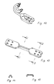
- the clip 1 has fixing lugs 2 its concave front curved part receiving a broken ring 3 whose ends 11, 11 'overlap.
- the fixing lugs have on their outer faces longitudinal grooves 4 and respectively 5 (not visible), which correspond on the opposite faces of the longitudinal reliefs 4 '(not visible) and 5'.
- Double points 6, 6 are intended for the subsequent fixing of the staples, passing through the holes in the grooves 4, 5 and the reliefs 4 ', 5'.
- Figure 2 shows how ring 3 is pinched by the edges 12, 12 oriented towards the concavity of the curved part of the clip.
- Figure 4 shows on the left a clip 1 fixed on the end a conveyor belt. Note that the 11 'end of the ring is in abutment against the front part 14 of the end of the conveyor belt. The bulging parts 10, 10 of the strip are also in contact with the front of the end of the conveyor belt 13. A connecting rod and articulation 15 is threaded into the rings. On the left side in the figure the other clip is shown still not fixed; we notice a double point 6 which is threaded through the holes in the lower tab of the clip, the upper tab of the clip not yet folded down.
- Figure 8 shows the cross section of the part narrow of the clip according to the cutting plane A-A of FIG. 7, the Figure 9 showing the cross section of the right tab of the Figure 7, along the section plane B-B of Figure 7.
- Figure 10 shows the initial stage of manufacturing sealing strips from a resilient metal strip, by cutting. Note the future slats 9 and the oblong part 8.
- the lamellae 9 have received their shape definitive and the oblong part 8 'has been deformed between the lamellae successive steps to achieve the 8 "recesses.
- Figure 13 shows the same clip as that of the Figure 12, at an intermediate stage of its manufacture.
- FIG. 16 shows an embodiment particular of the invention in which the sealing strip 8 does not has no 8 "recesses, and in which the slats 9 have no backward bulges in the area where they are connected to the oblong part 8 '.
- This is due to the method of attachment by welding on the rear parts of the rings 3, here of the rings closed.
- the oblong part 8 'of the strip seal 8 which is in abutment over its entire length with the part front 14 of the end of the conveyor belt.
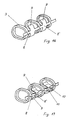
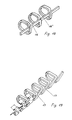
- Figure 18 shows a particular embodiment broken rings, interconnected by connecting parts 16 and 16 'generally parallel to the median plane of the ring sequence 3 passing through the largest dimension of the rings 3.
- Figure 19 shows rings linked together by oblique connecting parts 17, fixing the sealing strip intervening by welding against the rear face of the parts of oblique link 17.
- Figure 5 shows clearly the arrangement and spacing of the staples, in reality, and therefore imagine the layout and spacing rings, not visible, which they comprise.
Landscapes
- Engineering & Computer Science (AREA)
- General Engineering & Computer Science (AREA)
- Mechanical Engineering (AREA)
- Belt Conveyors (AREA)
Description
Claims (29)
- Dispositif de jonctionnement pour bande transporteuse constitué par deux rangées d'agrafes en forme générale de U, fixées sur le bord de chacune des extrémités de la bande transporteuse (13) au moyen de pointes simples ou doubles ou de rivets, la partie courbe des agrafes (1) en forme de U débordant au-delà des bords constituant les extrémités de la bande transporteuse, les parties concaves des agrafes (1) en forme de U formant une succession d'yeux délimités par lesdites parties concaves des agrafes et par le bord de l'extrémité de la bande transporteuse à laquelle sont fixées les agrafes, les agrafes de chacune des rangées étant placées entre les agrafes de l'autre rangée, de façon telle que les yeux des agrafes des deux rangées soient en alignement, dans le sens transversal de la bande, une tige métallique (15) formant axe de liaison et d'articulation étant enfilée dans ces yeux en alignement, caractérisé par le fait qu'un anneau (3) est fixé dans la partie concave de chacune des agrafes en forme de U, la tige métallique (15) formant axe de liaison et d'articulation étant enfilée dans lesdits anneaux successifs appartenant alternativement à l'une et à l'autre rangée d'agrafes (1).
- Dispositif de jonctionnement selon la revendication 1, caractérisé par le fait que la partie concave de l'agrafe (1) a un profil complémentaire de celui de la périphérie extérieure de l'anneau (3).
- Dispositif de jonctionnement selon les revendications 1 et 2, caractérisé par le fait que le profil de la périphérie de l'anneau (3) est plat, la partie concave de l'agrafe (1) en forme de U ayant un profil constitué par une partie médiane plate et par deux parties formant des bords relevés qui sont orientées vers l'intérieur de la concavité et qui encadrent l'anneau.
- Dispositif de jonctionnement selon les revendications 1 et 2, caractérisé par le fait que le profil de la périphérie de l'anneau (3) comporte une ou plusieurs parties en creux dans le sens périphérique, la partie concave de l'agrafe (1) en forme de U ayant un profil comportant une ou plusieurs parties en relief dans le sens périphérique de forme complémentaire de celle des parties en creux de la périphérie de l'anneau.
- Dispositif de jonctionnement selon les revendications 1 et 2, caractérisé par le fait que le profil de la périphérie de l'anneau (3) comporte, une ou plusieurs parties en relief, dans le sens périphérique, la partie concave de l'agrafe (1) en forme de U ayant un profil comportant, une ou plusieurs parties en creux, dans le sens périphérique, de forme complémentaire de celle des parties en relief de la périphérie de l'anneau (3).
- Dispositif de jonctionnement selon l'une quelconque des revendications précédentes, caractérisé par le fait que l'anneau (3) est un anneau brisé.
- Dispositif de jonctionnement selon l'une quelconque des revendications précédentes, caractérisé par le fait que l'anneau (3) est un anneau brisé, l'anneau brisé étant réalisé de façon telle que les extrémités de l'anneau brisé se chevauchent sur une certaine distance.
- Dispositif de jonctionnement selon l'une quelconque des revendications précédentes, caractérisé par le fait que les anneaux (3) sont réalisés sous la forme d'une suite d'anneaux (3) non complètement fermés reliés entre eux par des parties de liaison obliques (17) par rapport au plan médian de la suite d'anneaux (3) passant par la plus grande dimension intérieure des anneaux, en constituant une sorte d'hélice dont le pas est nul au niveau de chaque anneau non complètement fermé, les parties obliques de liaison (17) permettant de progresser jusqu'à l'anneau (3) non complètement fermé suivant, l'écart entre les anneaux (3) successifs correspondant à l'écart prévu pour le montage des agrafes (1) sur la bande transporteuse.
- Dispositif de jonctionnement selon l'une quelconque des revendications 1 à 7, caractérisé par le fait que les anneaux (3) sont réalisés sous la forme d'une suite d'anneaux (3) non complètement fermés reliés entre eux par des parties de liaison (16, 16') généralement parallèles au plan médian de la suite d'anneaux (3) passant par la plus grande dimension des anneaux (3), en constituant une sorte de méandre, le sens d'enroulement des anneaux (3) non complètement fermés étant inversé pour chaque anneau de la suite d'anneaux (3) par rapport au sens d'enroulement de l'anneau précédent, les parties de liaison généralement parallèles au plan médian longitudinal de la suite d'anneaux étant situées alternativement plus près du centre de l'anneau (3), puis plus loin, la partie reliant une des extrémités d'un anneau (3) à la partie de liaison (16) généralement parallèle au plan médian longitudinal et la partie reliant l'autre extrémité dudit anneau à l'autre partie de liaison (16) généralement parallèle au plan médian longitudinal, se chevauchant sur une certaine distance et étant très proches l'une de l'autre.
- Dispositif de jonctionnement selon l'une des revendications précédentes, caractérisé par le fait que les anneaux (3) sont fixés en étant pincés dans la partie concave des agrafes (1), entre les bords relevés orientés vers l'intérieur de la concavité.
- Dispositif de jonctionnement selon l'une quelconque des revendications précédentes, caractérisé par le fait que chaque anneau (3) est soudé en un ou plusieurs points à la partie courbe concave de l'agrafe (1) dans laquelle il est placé.
- Dispositif de jonctionnement selon l'une quelconque des revendications précédentes, caractérisé par le fait que les anneaux (3) ont une forme allongée du fait qu'elle comporte un demi-cercle à l'avant et un demi-cercle à l'arrière, reliés à leurs extrémités supérieures et à leurs extrémités inférieures par des parties rectilignes ou par des parties courbes présentant une légère concavité en direction de l'intérieur des anneaux.
- Dispositif de jonctionnement selon l'une quelconque des revendications précédentes, caractérisé par le fait que les anneaux (3) sont encliquetés dans la partie concave des agrafes (1), ladite partie concave des agrafes (1) ayant une forme s'étendant sur un peu plus que 180° et les anneaux (3) présentant une forme mâle correspondante autorisant la fixation ultérieure des agrafes (1) contre la bande transporteuse (13).
- Dispositif de jonctionnement selon l'une quelconque des revendications précédentes, caractérisé par le fait que les propriétés de résistance à l'usure du matériau des anneaux (3) sont supérieures à celles du matériau constituant les agrafes (1) en forme de U.
- Dispositif de jonctionnement selon l'une quelconque des revendications précédentes, caractérisé par le fait que les propriétés de glissement du matériau des anneaux (3) sont supérieures à celles du matériau constituant les agrafes (1) en forme de U.
- Dispositif de jonctionnement selon l'une quelconque des revendications précédentes, caractérisé par le fait que les propriétés de résistance à l'usure et les propriétés de glissement du matériau des anneaux (3) sont supérieures à celles du matériau constituant les agrafes (1) en forme de U.
- Dispositif de jonctionnement selon l'une quelconque des revendications précédentes, caractérisé par le fait qu'une bande d'étanchéité (8) est fixée aux parties arrières des anneaux (3), ladite bande d'étanchéité (8) comportant une partie oblongue (8') réalisée dans un matériau résilient plat, par découpe et formage ou par thermoformage et découpe, dont le profil correspond généralement à la courbure de la partie arrière de l'anneau (3) sur laquelle elle doit être fixée, ainsi que des lamelles d'étanchéité (9) rattachées à ladite partie oblongue (8') en formant une seule pièce avec elle, dont la surface et l'écartement correspondent respectivement à la surface et à l'écartement des parties supérieures et des parties inférieures des espaces vides qui existent entre la partie convexe des agrafes (1) d'une rangée et l'extrémité opposée de la bande transporteuse (13) et entre les agrafes (1) de l'autre rangée fixées sur ladite extrémité opposée, lorsque la jonction est réalisée, lesdites lamelles (9) étant disposées, par rapport à la partie oblongue (8'), à la façon des dents d'un râteau.
- Dispositif de jonctionnement selon la revendication 17, caractérisé par le fait que les lamelles (9) se présentent sous forme d'une seule rangée, du côté de la bande d'étanchéité (8), qui à l'état monté, est orientée vers l'extérieur de la bande transporteuse (3).
- Dispositif de jonctionnement selon la revendication 17, caractérisé par le fait que les lamelles (9) se présentent sous forme de deux rangées symétriques par rapport au plan de symétrie longitudinal partageant la partie oblongue (8') de la bande d'étanchéité (8).
- Dispositif de jonctionnement selon la revendication 17, 18 ou 19, caractérisé par le fait que la partie oblongue (8') de la bande d'étanchéité présente une suite de décrochements (8") dont l'écartement mutuel correspond à celui des anneaux (3) lorsque les agrafes (1) sont montées sur l'extrémité de la bande transporteuse (13), lesdits décrochements étant orientés dans la même direction que les lamelles d'étanchéité (9) et ayant une amplitude qui correspond à l'épaisseur des anneaux (3), les lamelles d'étanchéité (9) étant dans ce cas rattachées à la partie oblongue (8') de la bande d'étanchéité (8) par une partie courbe qui fait saillie vers l'arrière, par rapport à la partie oblongue (8') de la bande d'étanchéité, d'au moins autant que l'épaisseur des anneaux.
- Dispositif de jonctionnement selon la revendication 17, 18 ou 19, caractérisé par le fait que la bande d'étanchéité (8) est fixée aux anneaux (3) par une soudure effectuée contre la partie arrière des anneaux (3), les lamelles d'étanchéité (9) successives étant centrées entre les anneaux successifs.
- Dispositif de jonctionnement selon la revendication 20, caractérisé par le fait que la bande d'étanchéité (8) est fixée aux anneaux brisés successifs (3), ses décrochements (8") successifs étant pincés entre les extrémités chevauchantes (11, 11') des anneaux successifs.
- Dispositif de jonctionnement selon la revendication 22, caractérisé par le fait que les décrochements successifs de la bande d'étanchéité qui se trouvent pincés entre les extrémités chevauchantes (11, 11') des anneaux (3) successifs sont de plus soudés à celles-ci.
- Dispositif de jonctionnement selon la revendication 20, caractérisé par le fait que la bande d'étanchéité (8) est fixée aux anneaux (3) successifs du type méandre reliés entre eux, les décrochements successifs (8") étant pincés entre les extrémités chevauchantes des parties de liaison successives.
- Dispositif de jonctionnement selon la revendication 24, caractérisé par le fait que les décrochements successifs (8") de la bande d'étanchéité (8) qui se trouvent pincés entre les extrémités chevauchantes des parties de liaison (16, 16') successives d'anneaux reliés entre eux du type méandre sont de plus soudés à celles-ci.
- Dispositif de jonctionnement selon la revendication 17, caractérisé par le fait que la bande d'étanchéité (8) est fixée par soudure de sa partie oblongue contre la face arrière de la partie de liaison oblique (17) reliant des anneaux successifs du type en hélice, au droit des paires de lamelles (9) supérieures et inférieures.
- Dispositif de jonctionnement selon l'une quelconque des revendications précédentes, caractérisé par le fait qu'au moins une des pattes des agrafes (1) comporte sur sa surface inférieure orientée vers la bande transporteuse des reliefs (5") dont la direction générale, qu'ils soient rectilignes ou courbes, est oblique par rapport au sens longitudinal des pattes des agrafes et au sens longitudinal de la bande transporteuse lorsque les agrafes sont fixées sur celles-ci.
- Dispositif de jonctionnement selon la revendication 27, caractérisé par le fait que les reliefs (5") sont constitués par des prolongements, qui se croisent, des reliefs (5') qui correspondent aux sillons longitudinaux dans lesquels sont logées les têtes des pointes de fixation.
- Jonction réalisée au moyen d'un dispositif de jonctionnement selon l'une quelconque des revendications précédentes, caractérisée par le fait que les rangées d'agrafes (1) sont montées sur les extrémités de la bande transporteuse (13) de façon telle que la partie arrière des anneaux (3) de chaque rangée d'agrafes soit en butée contre la partie frontale (14) de l'extrémité de la bande transporteuse (13) sur laquelle elle est montée.
Applications Claiming Priority (2)
| Application Number | Priority Date | Filing Date | Title |
|---|---|---|---|
| FR9301391A FR2701300B1 (fr) | 1993-02-09 | 1993-02-09 | Dispositif de jonctionnement pour bande transporteuse. |
| PCT/FR1994/000960 WO1996003597A1 (fr) | 1993-02-09 | 1994-07-28 | Dispositif de jonctionnement pour bande transporteuse |
Publications (2)
| Publication Number | Publication Date |
|---|---|
| EP0720706A1 EP0720706A1 (fr) | 1996-07-10 |
| EP0720706B1 true EP0720706B1 (fr) | 1998-03-04 |
Family
ID=37110269
Family Applications (1)
| Application Number | Title | Priority Date | Filing Date |
|---|---|---|---|
| EP94923763A Expired - Lifetime EP0720706B1 (fr) | 1993-02-09 | 1994-07-28 | Dispositif de jonctionnement pour bande transporteuse |
Country Status (7)
| Country | Link |
|---|---|
| US (1) | US5669114A (fr) |
| EP (1) | EP0720706B1 (fr) |
| AU (1) | AU675345B2 (fr) |
| DE (1) | DE69408856T2 (fr) |
| FR (1) | FR2701300B1 (fr) |
| WO (1) | WO1996003597A1 (fr) |
| ZA (1) | ZA945551B (fr) |
Families Citing this family (16)
| Publication number | Priority date | Publication date | Assignee | Title |
|---|---|---|---|---|
| FR2701300B1 (fr) * | 1993-02-09 | 1995-03-31 | Aser Sarl | Dispositif de jonctionnement pour bande transporteuse. |
| EP0651178B1 (fr) * | 1993-10-29 | 1997-01-15 | Goro S.A. | Dispositif de jonction de courroie |
| DE19724084A1 (de) * | 1997-06-07 | 1998-12-10 | Goro Sa | Riemenverbinder |
| US6216851B1 (en) * | 1998-10-22 | 2001-04-17 | Flexible Steel Lacing Company | Rivet belt fastener |
| US6643899B2 (en) * | 2000-06-16 | 2003-11-11 | André Corriveau | Spiral for interconnecting ends of endless belt segments |
| US6896125B2 (en) * | 2003-04-04 | 2005-05-24 | Pflow Industries, Inc. | Belt attachment device and method |
| BRPI0710677A2 (pt) * | 2006-04-07 | 2011-08-23 | Michael Pietsch | arranjo de acoplamento e sistema para transportador de transporte contìnuo |
| FR2921141B1 (fr) | 2007-09-19 | 2010-03-12 | Aser Sarl | Dispositif perfectionne de jonction pour bandes transportables |
| GB2469651A (en) * | 2009-04-21 | 2010-10-27 | Allan Richard Manninen | Seaming device for an industrial fabric |
| CA2700767A1 (fr) * | 2010-04-16 | 2011-10-16 | Allan Richard Manninen | Element de couture filamentaire pour un tissu industriel et tissu industriel cousu au moyen de cet element |
| DE102011082267A1 (de) * | 2011-09-07 | 2013-03-07 | Aktiebolaget Skf | Tragefördermittellagereinheit |
| RU2707434C2 (ru) | 2014-08-18 | 2019-11-26 | Флексибл Стил Лейсинг Компани | Соединитель конвейерных лент и способ его изготовления |
| USD808253S1 (en) | 2014-08-18 | 2018-01-23 | Flexible Steel Lacing Company | Fastener for a conveyor belt |
| FR3038027B1 (fr) * | 2015-06-25 | 2018-07-06 | Aser | Agrafes pour dispositifs de jonctionnement des extremites d'une bande transporteuse |
| RU198088U1 (ru) * | 2019-01-09 | 2020-06-17 | Общество С Ограниченной Ответственностью "Спк-Стык" | Шарнирный соединитель конвейерных лент |
| US12055195B2 (en) | 2022-01-28 | 2024-08-06 | Flexible Steel Lacing Company | Conveyor belt fastener |
Family Cites Families (17)
| Publication number | Priority date | Publication date | Assignee | Title |
|---|---|---|---|---|
| FR1313652A (fr) * | 1962-02-06 | 1962-12-28 | Hayden Nilos Ltd | Agrafe pour courroies |
| DE1807684B1 (de) * | 1968-11-08 | 1969-12-18 | Nilos Gmbh | Foerderband- und Treibriemenverbindungen mit Doppelhaken |
| US3737954A (en) * | 1970-10-19 | 1973-06-12 | C Tabler | Connector for flexible belts |
| FR2342432A1 (fr) * | 1976-02-27 | 1977-09-23 | Goro | Agrafe de jonction pour courroies ou tapis transporteurs |
| FR2566477B1 (fr) * | 1984-06-26 | 1987-08-21 | Goro Sa | Axe flexible pour la reunion et l'articulation des agrafes de jonction d'un tapis transporteur |
| US4611367A (en) * | 1985-06-21 | 1986-09-16 | Clipper Belt Lacer Company | Hook keeper for belt lacings |
| FR2624940A1 (fr) * | 1987-12-17 | 1989-06-23 | Goro Sa | Axe de jonction pour l'accouplement des extremites d'un tapis transporteur ou similaire |
| DE3843872A1 (de) * | 1988-12-24 | 1990-06-28 | Mato Masch & Metallwaren | Foerderbandverbinder |
| EP0437639B1 (fr) * | 1989-12-14 | 1993-11-10 | Goro S.A. | Joint d'étanchéité de la jonction de deux tronçons d'un tapis transporteur et dispositif de jonction comportant un tel joint |
| FR2666527B1 (fr) * | 1990-09-10 | 1995-01-27 | Goro Sa | Procede de fabrication de dispositifs de jonction pour tapis transporteurs ou similaires, et dispositifs de jonction ainsi fabriques. |
| DE4110818C1 (fr) * | 1991-04-04 | 1992-09-17 | Mato Maschinen- Und Metallwarenfabrik Curt Matthaei Gmbh & Co Kg, 6050 Offenbach, De | |
| US5236079A (en) * | 1991-06-05 | 1993-08-17 | Mato Maschinen-Und Metallwarenfabrik Curt Matthaei Gmbh & Co Kg | Belt fastener arrangement |
| DE4235759A1 (de) * | 1992-10-23 | 1994-05-05 | Mato Masch & Metallwaren | Verfahren zum Verbinden der Gurtenden von Förderbändern und Verbindungsmittel hierfür |
| FR2701300B1 (fr) * | 1993-02-09 | 1995-03-31 | Aser Sarl | Dispositif de jonctionnement pour bande transporteuse. |
| US5327823A (en) * | 1993-05-03 | 1994-07-12 | Ford New Holland, Inc. | Splice for round baler belts |
| US5415913A (en) * | 1993-05-03 | 1995-05-16 | New Holland North America, Inc. | Method of splicing round baler belts |
| FR2706964B1 (fr) * | 1993-06-21 | 1995-09-01 | Aser Sarl |
-
1993
- 1993-02-09 FR FR9301391A patent/FR2701300B1/fr not_active Expired - Fee Related
-
1994
- 1994-07-27 ZA ZA945551A patent/ZA945551B/xx unknown
- 1994-07-28 US US08/617,783 patent/US5669114A/en not_active Expired - Lifetime
- 1994-07-28 AU AU73869/94A patent/AU675345B2/en not_active Ceased
- 1994-07-28 DE DE69408856T patent/DE69408856T2/de not_active Expired - Fee Related
- 1994-07-28 EP EP94923763A patent/EP0720706B1/fr not_active Expired - Lifetime
- 1994-07-28 WO PCT/FR1994/000960 patent/WO1996003597A1/fr not_active Ceased
Also Published As
| Publication number | Publication date |
|---|---|
| DE69408856D1 (de) | 1998-04-09 |
| EP0720706A1 (fr) | 1996-07-10 |
| US5669114A (en) | 1997-09-23 |
| DE69408856T2 (de) | 1998-10-15 |
| WO1996003597A1 (fr) | 1996-02-08 |
| FR2701300B1 (fr) | 1995-03-31 |
| FR2701300A1 (fr) | 1994-08-12 |
| AU675345B2 (en) | 1997-01-30 |
| ZA945551B (en) | 1995-03-07 |
| AU7386994A (en) | 1996-02-22 |
Similar Documents
| Publication | Publication Date | Title |
|---|---|---|
| FR2701300A1 (fr) | Dispositif de jonctionnement pour bande transporteuse. | |
| EP1725787B1 (fr) | Elements de jonction incorpores a des extremites de bande transporteuse | |
| EP2789888B1 (fr) | Dispositif de serrage pour l'accouplement étanche de tubes lisses | |
| WO2010004233A1 (fr) | Dispositif de serrage comprenant un collier | |
| FR2510438A1 (fr) | Procede de fabrication de cages en tole pour des paliers a roulement | |
| FR2526278A1 (fr) | Fermeture a glissiere comportant des elements d'accouplement discrets perfectionnes | |
| EP0294301A1 (fr) | Dispositif de solidarisation temporaire des extrémités de deux structures dont au moins une est souple | |
| EP0468841A1 (fr) | Convoyeur à bande sans fin | |
| EP0371853B1 (fr) | Reliure pour album d'échantillons | |
| CA2488986C (fr) | Tapis de convoyage | |
| FR2818352A1 (fr) | Collier de serrage | |
| EP0558390B1 (fr) | Lame profilée pour fermeture à rideau, et rideau de fermeture correspondant | |
| EP0437639B1 (fr) | Joint d'étanchéité de la jonction de deux tronçons d'un tapis transporteur et dispositif de jonction comportant un tel joint | |
| EP0669444B1 (fr) | Lame profilée pour fermeture à rideau et rideau de fermeture correspondant | |
| EP0006664B1 (fr) | Bracelet constitué de maillons rigides directement articulés les uns aux autres | |
| FR2807465A1 (fr) | Agencement de store roulant du type a lamelles articulees et a profiles de guidage des extremites des lamelles | |
| EP0164790B1 (fr) | Bague de cerclage et de stockage pour bobine de ruban d'enregistrement | |
| EP1213434B2 (fr) | Lame profilée pour fermeture à rideau | |
| EP0976960B1 (fr) | Collier de serrage à vis tangente | |
| FR2593872A1 (fr) | Dispositif de jonction des extremites d'un tapis transporteur | |
| FR2818351A1 (fr) | Collier de serrage | |
| FR2746441A1 (fr) | Lames profilees pour fermeture a rideau et rideau de fermeture comprenant de telles lames | |
| FR2517928A1 (fr) | Taquet ou bec cueilleur pour chaine de machine agricole | |
| BE525301A (fr) | ||
| BE571116A (fr) |
Legal Events
| Date | Code | Title | Description |
|---|---|---|---|
| PUAI | Public reference made under article 153(3) epc to a published international application that has entered the european phase |
Free format text: ORIGINAL CODE: 0009012 |
|
| 17P | Request for examination filed |
Effective date: 19960401 |
|
| AK | Designated contracting states |
Kind code of ref document: A1 Designated state(s): DE GB IT |
|
| GRAG | Despatch of communication of intention to grant |
Free format text: ORIGINAL CODE: EPIDOS AGRA |
|
| 17Q | First examination report despatched |
Effective date: 19961213 |
|
| GRAH | Despatch of communication of intention to grant a patent |
Free format text: ORIGINAL CODE: EPIDOS IGRA |
|
| GRAH | Despatch of communication of intention to grant a patent |
Free format text: ORIGINAL CODE: EPIDOS IGRA |
|
| GRAA | (expected) grant |
Free format text: ORIGINAL CODE: 0009210 |
|
| AK | Designated contracting states |
Kind code of ref document: B1 Designated state(s): DE GB IT |
|
| REF | Corresponds to: |
Ref document number: 69408856 Country of ref document: DE Date of ref document: 19980409 |
|
| ITF | It: translation for a ep patent filed | ||
| GBT | Gb: translation of ep patent filed (gb section 77(6)(a)/1977) |
Effective date: 19980515 |
|
| PLBE | No opposition filed within time limit |
Free format text: ORIGINAL CODE: 0009261 |
|
| STAA | Information on the status of an ep patent application or granted ep patent |
Free format text: STATUS: NO OPPOSITION FILED WITHIN TIME LIMIT |
|
| 26N | No opposition filed | ||
| REG | Reference to a national code |
Ref country code: GB Ref legal event code: IF02 |
|
| PGFP | Annual fee paid to national office [announced via postgrant information from national office to epo] |
Ref country code: GB Payment date: 20040722 Year of fee payment: 11 |
|
| PG25 | Lapsed in a contracting state [announced via postgrant information from national office to epo] |
Ref country code: IT Free format text: LAPSE BECAUSE OF NON-PAYMENT OF DUE FEES Effective date: 20050728 Ref country code: GB Free format text: LAPSE BECAUSE OF NON-PAYMENT OF DUE FEES Effective date: 20050728 |
|
| GBPC | Gb: european patent ceased through non-payment of renewal fee |
Effective date: 20050728 |
|
| PGFP | Annual fee paid to national office [announced via postgrant information from national office to epo] |
Ref country code: DE Payment date: 20060727 Year of fee payment: 13 |
|
| PG25 | Lapsed in a contracting state [announced via postgrant information from national office to epo] |
Ref country code: DE Free format text: LAPSE BECAUSE OF NON-PAYMENT OF DUE FEES Effective date: 20080201 |