EP0720785B1 - Elektrische maschine - Google Patents
Elektrische maschine Download PDFInfo
- Publication number
- EP0720785B1 EP0720785B1 EP95924947A EP95924947A EP0720785B1 EP 0720785 B1 EP0720785 B1 EP 0720785B1 EP 95924947 A EP95924947 A EP 95924947A EP 95924947 A EP95924947 A EP 95924947A EP 0720785 B1 EP0720785 B1 EP 0720785B1
- Authority
- EP
- European Patent Office
- Prior art keywords
- machine according
- winding
- windings
- circuit
- power
- Prior art date
- Legal status (The legal status is an assumption and is not a legal conclusion. Google has not performed a legal analysis and makes no representation as to the accuracy of the status listed.)
- Expired - Lifetime
Links
- 238000004804 winding Methods 0.000 claims abstract description 168
- 239000004020 conductor Substances 0.000 claims description 46
- 238000001816 cooling Methods 0.000 claims description 38
- 239000002826 coolant Substances 0.000 claims description 21
- 239000011295 pitch Substances 0.000 claims description 20
- 239000003990 capacitor Substances 0.000 claims description 18
- 239000007788 liquid Substances 0.000 claims description 4
- 230000008901 benefit Effects 0.000 description 6
- 230000002349 favourable effect Effects 0.000 description 6
- 230000000630 rising effect Effects 0.000 description 5
- 238000010276 construction Methods 0.000 description 3
- 230000005611 electricity Effects 0.000 description 3
- 230000002441 reversible effect Effects 0.000 description 3
- 239000004065 semiconductor Substances 0.000 description 3
- 230000009286 beneficial effect Effects 0.000 description 2
- 230000008859 change Effects 0.000 description 2
- 230000000694 effects Effects 0.000 description 2
- 238000005516 engineering process Methods 0.000 description 2
- 230000017525 heat dissipation Effects 0.000 description 2
- 230000006698 induction Effects 0.000 description 2
- 230000000737 periodic effect Effects 0.000 description 2
- 238000006424 Flood reaction Methods 0.000 description 1
- 230000015572 biosynthetic process Effects 0.000 description 1
- 230000008878 coupling Effects 0.000 description 1
- 238000010168 coupling process Methods 0.000 description 1
- 238000005859 coupling reaction Methods 0.000 description 1
- 230000007423 decrease Effects 0.000 description 1
- 230000003247 decreasing effect Effects 0.000 description 1
- 238000010586 diagram Methods 0.000 description 1
- 230000005672 electromagnetic field Effects 0.000 description 1
- 230000004907 flux Effects 0.000 description 1
- 230000001976 improved effect Effects 0.000 description 1
- 230000001939 inductive effect Effects 0.000 description 1
- 239000000463 material Substances 0.000 description 1
- 230000000149 penetrating effect Effects 0.000 description 1
- 230000010363 phase shift Effects 0.000 description 1
- 238000004382 potting Methods 0.000 description 1
- 230000009467 reduction Effects 0.000 description 1
- 238000005096 rolling process Methods 0.000 description 1
- 239000000523 sample Substances 0.000 description 1
Images







Classifications
-
- H—ELECTRICITY
- H02—GENERATION; CONVERSION OR DISTRIBUTION OF ELECTRIC POWER
- H02P—CONTROL OR REGULATION OF ELECTRIC MOTORS, ELECTRIC GENERATORS OR DYNAMO-ELECTRIC CONVERTERS; CONTROLLING TRANSFORMERS, REACTORS OR CHOKE COILS
- H02P27/00—Arrangements or methods for the control of AC motors characterised by the kind of supply voltage
- H02P27/04—Arrangements or methods for the control of AC motors characterised by the kind of supply voltage using variable-frequency supply voltage, e.g. inverter or converter supply voltage
-
- H—ELECTRICITY
- H02—GENERATION; CONVERSION OR DISTRIBUTION OF ELECTRIC POWER
- H02K—DYNAMO-ELECTRIC MACHINES
- H02K11/00—Structural association of dynamo-electric machines with electric components or with devices for shielding, monitoring or protection
- H02K11/30—Structural association with control circuits or drive circuits
- H02K11/33—Drive circuits, e.g. power electronics
-
- H—ELECTRICITY
- H02—GENERATION; CONVERSION OR DISTRIBUTION OF ELECTRIC POWER
- H02K—DYNAMO-ELECTRIC MACHINES
- H02K17/00—Asynchronous induction motors; Asynchronous induction generators
- H02K17/02—Asynchronous induction motors
- H02K17/30—Structural association of asynchronous induction motors with auxiliary electric devices influencing the characteristics of the motor or controlling the motor, e.g. with impedances or switches
-
- H—ELECTRICITY
- H02—GENERATION; CONVERSION OR DISTRIBUTION OF ELECTRIC POWER
- H02K—DYNAMO-ELECTRIC MACHINES
- H02K3/00—Details of windings
- H02K3/04—Windings characterised by the conductor shape, form or construction, e.g. with bar conductors
- H02K3/28—Layout of windings or of connections between windings
-
- H—ELECTRICITY
- H02—GENERATION; CONVERSION OR DISTRIBUTION OF ELECTRIC POWER
- H02K—DYNAMO-ELECTRIC MACHINES
- H02K17/00—Asynchronous induction motors; Asynchronous induction generators
- H02K17/02—Asynchronous induction motors
- H02K17/16—Asynchronous induction motors having rotors with internally short-circuited windings, e.g. cage rotors
-
- H—ELECTRICITY
- H02—GENERATION; CONVERSION OR DISTRIBUTION OF ELECTRIC POWER
- H02K—DYNAMO-ELECTRIC MACHINES
- H02K5/00—Casings; Enclosures; Supports
- H02K5/04—Casings or enclosures characterised by the shape, form or construction thereof
- H02K5/20—Casings or enclosures characterised by the shape, form or construction thereof with channels or ducts for flow of cooling medium
- H02K5/203—Casings or enclosures characterised by the shape, form or construction thereof with channels or ducts for flow of cooling medium specially adapted for liquids, e.g. cooling jackets
-
- H—ELECTRICITY
- H02—GENERATION; CONVERSION OR DISTRIBUTION OF ELECTRIC POWER
- H02K—DYNAMO-ELECTRIC MACHINES
- H02K5/00—Casings; Enclosures; Supports
- H02K5/04—Casings or enclosures characterised by the shape, form or construction thereof
- H02K5/22—Auxiliary parts of casings not covered by groups H02K5/06-H02K5/20, e.g. shaped to form connection boxes or terminal boxes
- H02K5/225—Terminal boxes or connection arrangements
Definitions
- the invention relates to an electrical machine, comprising a machine housing, one in the machine housing by one Rotor axis rotatably mounted rotor, one in the machine housing arranged stator, one of the stator or the rotor assigned winding and a field generation in the Winding control circuit with one DC link and at least one between it and the winding arranged power controller and one Control for the power controller, all of which Field generation in the winding controlling power controller in the machine housing are arranged.
- Such electrical machines are preferably so-called inverter controlled machines. With these is about Power controller for generating fields in the winding serving current in terms of frequency amplitude and phase controlled.
- the invention has for its object an electrical To create a machine in which the occurring Stray fields can be further reduced. Another The task is to determine the relationship between performance and To improve the size and weight of the machine.
- this solution has the great advantage that with this Division of the winding into four or more partial windings and the feeding of the partial windings according to the invention at least two or more circuits either the Possibility is created that over every circuit in the To reduce winding currents to be fed and thus To be able to dimension circuits smaller, the same Power of the electric machine as with the well-known star or delta connection is achievable, however not - how with the star and delta connection ultimately everyone Circuit to the maximum flowing in the winding Current and the maximum voltage must be designed, or there is the possibility, with the same interpretation of the Circuits to increase performance.
- Another advantage of this solution according to the invention is to see that this offers the possibility of the Frequency of current or voltage in each Circuits with the same specific power of the circuit to increase because of an increase in the frequency of electricity and voltage a higher reactive current in the circuits entails that, however, when divided over several circuits does not cause technical problems.
- the increase in the frequency of current and voltage in the individual circuits is compared to the conventional Three-phase motor possible by a factor which is the quotient divided by the number of corners of the polygon circuit corresponds to three.
- the solution according to the invention is particularly advantageous if if pole numbers of more than eight prove to be advantageous, since these can be implemented without problems, whereas for example in conventional electrical asynchronous machines in star or delta connection with pole numbers of more than eight the power of the electrical machine decreases.
- Poles of more than 14 are also no problem example of 28 for a hexagonal polygon circuit, realizable
- the solution according to the invention is particularly suitable if the winding has multiple strands and if for control field generation in each strand for this at least one Power controller is provided. This is particularly the Problems of large electromagnetic stray fields with a lot stranded machines significantly reduced because in this case with one arranged outside the machine housing Power controllers leading a variety of high currents Supply lines from the power controllers to the machine housing and have to be led into it.
- the care of the individual is particularly easy Power controller via the DC link then solved when the DC link two around the Rotor axis and at least partially circumferentially arranged comprises parallel conductor bows, on to which the power controllers are connected.
- Such Design of the DC link in the Machine housing has the great advantage that this one has low inductance and thus already from this Because of the small stray fields generated.
- the ladder bracket are formed as a flat conductor, preferably the Broad side of the flat conductor runs parallel to the plane, in which these extend.
- a particularly advantageous solution provides that the two Ring conductors are arranged concentrically to each other.
- Power controllers are arranged on one side of the plane in which the conductor brackets lie, so that the possibility consists of the power controller on one of the conductor brackets cooling the opposite side as effectively as possible.
- each power controller an intermediate circuit storage capacitor is assigned which expediently with its connections as close as possible to the connections of the power controller sits around the Minimize inductance.
- a particularly favorable arrangement, especially with regard to the proximity between the connections of the power controller and the intermediate circuit storage capacitor is then possible if on the side opposite the power controllers the intermediate circuit storage capacitors are located on the level.
- the Actuator control is arranged near the power controller.
- a particularly favorable way of arranging the Actuator control is given when the actuator control in the spaces between the DC link storage probes is arranged.
- the actuator control sits near the conductor bracket, because it is optimally short distances between the controller and those controlled by it Service providers are possible.
- a particularly advantageous embodiment of the invention is that in the machine housing arranged power controllers are cooled so that as Switches in the power controllers also use semiconductors and can be loaded up to the maximum possible current.
- the power controller have a heat sink.
- This heat sink could, for example of air swirled in the machine housing flowed to and thus cooled.
- the cooling element of is flowed through a liquid cooling medium, because with a Such cooling larger amounts of heat can be dissipated than with Air cooling.
- a particularly effective cooling is possible if the Power controller have a heat sink, which in one cooling channel through which the liquid cooling medium flows of the cooling element protrudes.
- the power controller is not only cooled, but also be held mechanically firmly in the machine housing should, it is advantageously provided that the Power controller in the machine housing from the cooling element are held, the cooling element thus a carrier for the power controller, which in turn is on the machine housing is held. It is particularly advantageous here if the cooling element is part of the machine housing, so that there is a mechanically integrated solution; in which the Cooling element is not only able to power controllers to cool, but also at the same time the machine housing cool.
- the cooling element is formed by a wall area of the machine housing, preferably the bearing plate of the Machine housing can be used, since this is for simultaneous Training as a cooling element is very suitable.
- a particularly advantageous assembly of the invention Power controller in the cooling element provides that the Power controller a cover for an opening of the cooling channel forms in the cooling element and thus in a simple manner can be mounted that the heat sink from the the cooling channel flowing around the cooling medium.
- a particularly favorable solution provides that the cooling element is integrated in a cooling circuit of the stator, so that simultaneously with the cooling of the power controllers cooling of the stator by a single cooling circuit is feasible.
- the machine according to the invention is preferably designed such that that the winding fed via the power controller is the stator winding.
- Accessibility to the power controllers during assembly can be further improved if this sit inside a rotor winding.
- the type of power controllers used has not been specified in more detail. It is advantageously provided that the power controllers have at least one power controller block comprise, wherein each power controller block one Center tap and between the center tap and the positive supply voltage of the intermediate circuit and the Center tap and the negative supply voltage of the intermediate circle at least one or more controlled in parallel Has switches, in particular semiconductors and the Center tap with the feed connection for the respective Strand or the respective partial winding of the winding connected is.
- each power controller has several Power controller blocks, each for power supply a partial winding or a strand is particularly advantageous it is, however, if each power controller has only one Power controller block includes and therefore for each Partial winding or each strand required power controller blocks in the invention described above Are arranged in the machine housing.
- Machine To in one embodiment of the invention Machine must generate a pole field that is as symmetrical as possible it turned out to be particularly beneficial if in each Circuit the current is essentially even on the two sets of partial windings of the winding is distributed.
- the construction of a machine is particularly simple when all partial windings of the winding are essentially the same are, i.e. essentially the same reactance have and work with the same forces.
- the partial windings are wound so that in the polygon circuit opposing partial windings in side by side lying pole grooves of the stator or the rotor.
- the pole field realize In order to can be a particularly advantageous structure of the pole field realize.
- Partial windings are provided so that the partial windings are in the stator are wound that successive in the polygon Partial windings in side by side Pole slots lie.
- beginning and end of all in the polygon circuit successive partial windings in one small stator area or rotor area, which one or corresponds to two pole pitches. This would be For example, it makes sense if the supply lines to the Partial windings from the asynchronous machine according to the invention should be brought out.
- An even distribution of the beginning and end of successive Partial windings can be reached if Beginning and end in the polygon circuit consecutive Partial windings by at least the integer number of pole pitches the winding are offset, the next smaller integer of the quotient from the number of poles and the Number of strands corresponds.
- the strands of the winding depend on it with the pole field together that every strand in every pole to build the pole field contributes in the same way or expressed differently each strand in a pole division with the same number of Turns occurs.
- the periodically changing current in a selected circuit versus the current in a closest circuit is out of phase.
- the phase shift can be selected in a variety of ways become. It is particularly advantageous if the periodically changing current in a selected circuit compared to the current in a nearby circuit a phase angle of 360 ° divided by the number of Partial windings is out of phase.
- the periodically changing current in the individual circuits could in principle be a periodic rectangular current his.
- the in all Circuits of the polygon circuit currents flowing have such a time course that at each time point in the time derivative of at least one of the circuits Current is not equal to zero, that is, to each Time of electricity in at least one of the circuits changes, which means that the polar field also changes to everyone Time moved around the rotor axis.
- the half-wave shape the currents in the circuits is selected so that the rising and falling edge area of the half wave divided together over a phase angle of at least 360 ° run through the number of partial windings.
- the rising flank area and the descending flank areas are the same and run in each case at least over a phase angle of at least 360 ° divided by twice the number of partial windings.
- the magnetic flux of every single tooth can however, be increased when the half waveform is one rising and a falling flank area and one has a broadened maximum range in between.
- the maximum range two by the rising and the falling Flank area limited maxima and an intermediate one small minimum with about 80% of the maximum value, yet better about 90% of the maximum value.
- the Half waveform is trapezoidal, so that the Maximum range between the essentially linear rising and essentially linearly falling edge is essentially constant.
- the maximum range preferably extends over a Phase angle of maximum 360 ° divided by half the number of the partial windings.
- each circuit is on each supply connection a power controller is provided so that the two in each Power controller lying through a common circuit Actuator controls are controlled.
- the winding is preferred the stator winding, since this is in the idle system and therefore the easiest to feed.
- the solution according to the invention can be particularly advantageous in asynchronous machines, preferably in traction motors of motor vehicles.
- the rotor is preferably provided with a short circuit winding, though other types of winding would also be conceivable.
- An embodiment of an electric machine according to the invention is constructed as an asynchronous motor and includes, as in Fig. 2, a rotor 10 with a Rotor axis 12 rotatable rotor shaft 14 which has a rotor flange 16 carries, which in turn on its radially outer End is formed as a shoulder 18 on which is a winding ring designated as a whole by 20 sits, in which, as shown in Fig. 3, one as Whole with 22 designated rotor winding sits, the short-circuit winding is formed and parallel to the rotor axis 12 winding bars running in recesses 24, each with a short-circuit ring on the front 26 and 28 are short-circuited.
- the rotor 10 is in turn preferably via as a rolling bearing trained bearings 30 and 32 with one as a whole 40 designated machine housing, which a front bearing plate 42 and a rear bearing plate 44 includes and one between the end plates 42 and 44th lying outer housing shell 46, which is fixed to the two end shields 42 and 44 is connected.
- FIG. 3 are of an inner cylindrical surface 56 of the winding ring 52 starting in this pole slots 58 provided, through which the whole designated 60 Stator winding runs through.
- the stator winding 60 comprises a total of six strands S1, S2, S3, S4, S5 and S6. All these strands S1 to S6 are in the form of a polygon circuit interconnected, with corners of the polygon as Link points V1 to V6 of the strands S1 to S6 are formed are and between two in the polygon circuit successive tie points V one the strands S1 to S6. For example between node V1 and V2, strand S1, between node V2 and V3, strand S3, between nodes V3 and V4, strand S5, between tie points V4 and V5, strand S2, between nodes V5 and V6 of strand S4 and between nodes V6 and V1 of strand S6.
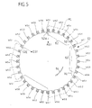
- Each of the strands S is, as in FIG. 5, based on a simplified one Winding ring 52 with fewer pole slots 58 than in the Reality present, represented.
- the turns lie here WS opposite each other in the polygon circuit Strands S side by side. So follows the turn WS1 of the Strand S1 the winding WS2 of strand S2, on this the Winding WS3 of the strand S3, then the winding WS4 of the Strand S4, the winding WS5 of strand S6 and finally the winding WS6 of the strand S6, all of which are consecutive
- turns WS1 to WS6 into one certain current flows through in the same direction are. All of these in the adjacent pole grooves 52 form lying windings WS1 to WS6 of the strands S1 to S6 together one designated as pole pitch 62 of the stator 50 Angular sector of the stator winding 60.
- this pole pitch 62 ' is followed by a pole pitch in the same direction as the pole division 62 current flows and in successive pole grooves 52 lying side by side WS1 to WS6.
- pole divisions 62 and 62 alternate for as long as until after one revolution in the winding ring 52 the last one Pole pitch 62 'connects to the first pole pitch 62.
- the illustrated embodiment has a total of 28 pole pitches 62, 62 ', so that a pole field with 28 poles can generate.
- the turns are WS1 in successive pole pitches by rear ends arranged on both sides of the winding ring 52 Connection lines HL and front connection lines VL connected so that in successive pole pitches 62, 62 'in each case the same winding WS1 the current seen in the direction of the rotor axis 12 in reverse Directions flow, as in Fig. 5 using the example of the turns WS1 in the successive pole pitches 62 and 62 ' indicated.
- the windings WS1 of the strand S1 are on for the connection with the points V1 and V2 suitable points of the Winding ring 52 led out, this between successive In principle, pole pitches 62 and 62 'on any Winding position can take place in the winding ring 52.
- the start AS1 of line S1 is in FIG a pole groove 52A and thus one end ES1 of the strand S1 in Direction of winding 64 of strand S1 seen in the pole slot 52E, which is opposite to the pole groove 52A by six pole grooves is offset to the winding direction 64.
- the other strands S2 to S6 are in an analogous manner in the Wrapped ring 52 wrapped with the winding direction the strands S1, S3 and S5 correspond to the winding direction 64, while the winding direction of the strands S6, S4 and S2 runs opposite to the winding direction 64.
- the beginning and end of the individual strands are S1 to S6 so that they are as close as possible to the respective Link point V lie.
- Fig. 6 shows the beginnings AS1 and AS6 of the strands S1 and S6 close to node V1
- the start AS3 of Line S3 and the end ES1 of line S1 close to the junction V2
- the End ES5 and end ES2 close to node V4
- the start AS2 of the line S2 and the end ES4 of the line S4 close to node V5 and the end ES6 of Strand S6 and the start AS4 of strand S4 close to the junction point V6.
- Each of the power controller blocks SB1 to SB6 comprises two Switches 70 and 72, with switch 70 being a center tap 74 with a positive DC link voltage + and with the switch 72, the center tap 74 with a negative DC link voltage - can be connected and the center tap 74 in turn directly connected to the respective supply connection SP is.
- the switches 70 and 72 are preferably Semiconductor switches, which via control lines 76 and 78 are controllable.
- All control lines 76 and 78 of each of the power controller blocks SB1 to SB6 are part of a common, as a whole 80 designated controller control and are run by this controlled together.
- the entire stator winding 60 thus over a total of 6 power controller blocks SB1 to SB6 fed.
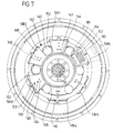
- the power controller blocks SB1 to SB6 in the same radial Distance from and around the rotor axis 12, all power control blocks SB1 to SB6 on one wall 82 of the rear end plate 44 sit, and between them Wall 82 and a rear wall 84 of the rear bearing plate 44 a coolant channel 86 is provided, which from a in flows through a defined direction flowing coolant is.
- Wall 82, rear wall 84, and coolant channel 86 together form a cooling element 87.
- the coolant channel 86 preferably runs in a radial direction Direction to the rotor axis 12 and is radial provided internal coolant inlet 88, from which then proceeding from the coolant in the radial direction 90 leads to a collecting duct 92 from the outside then the collected coolant, for example by a Coolant outlet flows out.
- Each of the power controller blocks SB comprises a mounting flange 94, and, one on one side of the mounting flange 94 seated heat sink 96, the thermal with the switches 70 and 72 is coupled, and one on the heat sink 96 opposite side of the mounting flange 94 seated Circuit body 98, in which electronic components of the power control block LSB housed and preferably are cast in a potting block for protection.
- every power controller block SB with its heat sink 96 can dip into the coolant channel 68 is the wall 82 at the seat of each SB power block with a breakthrough 100 provided, which by means of the mounting flange 94 a power control block SB mounted on the wall 82 can be closed in a coolant-tight manner, so that the coolant channel side of the mounting flange 94 arranged heat sink 96 lies fully in the coolant channel 86 and of the coolant is flowed around in the flow direction 90 thereof, preferably the heat sink 96 is also parallel to the Flow direction 90 of the coolant-extending ribs 102 and intermediate grooves 104 through which the Coolant flows in the direction of its flow direction 90.
- each power controller block LSB provided a separate coolant inlet 88 so that each of the power controller blocks SB with coolant defined Temperature can be flowed during, for example Removal of the coolant via the all-round collecting duct 92 and a common outlet 106 can take place.
- a power supply for the individual power control blocks SB takes place via two concentrically arranged to the rotor axis 12 Ring conductors 108 and 110, which are made of flat material are, and in a perpendicular to the rotor axis 12 Level 112 lie, with their flat sides 114 and 116 run parallel to plane 112.
- the ring conductor 108 and 110 lie on a flange 94 facing away from the mounting flange Top 118 of the circuit body 98 of the power controller blocks SB on and are with the circuit body 98th protruding connecting pins 120 and 122 connected, the Connection pins 120 and 122 expediently bores 124 or 126 reach through in the ring conductors 108 or 110 and can be screwed with these ..
- the ring conductors 108 and 110 are therefore off the wall via the power control blocks SB 82 of the rear bearing plate 44 worn.
- the ring conductor 108 lies, for example, on the negative one DC link voltage -, while the ring conductor 110 lies on the positive DC link voltage +.
- the formation of the power supply to the power control blocks SB over the ring conductors 108 and 110 has the big one Advantage that with these ring conductors 108 and 110 DC link with low inductance are formed can.
- the current feed into the two ring conductors 108 and 110 takes place from the machine housing 40, preferably the rear end shield 44 of the same, near the bearing 30 led out DC link leads 130 and 132, respectively are connected to the ring conductors 108 and 110, respectively.
- DC link leads 130 and 132 are provided, which to a common DC link supply connection are guided outside the machine housing 40.
- At least one intermediate circuit storage capacitor 140 is assigned to each power controller block SB, which is located on a side of the plane 112 opposite the respective power controller block SB and also with the ring conductors 108 and 110, preferably as close as possible to the connecting pins 120 or 122 of the respective power controller block SB, is connected.
- a preferred arrangement provides that the intermediate circuit storage capacitors 140 are located to the side of the respective power controller block SB, so that their connections can be connected to the ring conductors 108 and 110 if there is a gap between two successive power controller blocks SB.
- the intermediate circuit storage capacitors 140 are through one from the rear end plate 44 inside the Machine housing 40 protruding ring flange 142 against Vibrations supported, which is a cylindrical to Rotor axis 12 has circumferential support surface 144 which fixes the intermediate circuit storage capacitors 140 are.
- controller 80 is in or in arranged a plurality of circuit blocks 146, each on the one opposite a power controller block SB Level 112 side between the DC link storage capacitor 140 and also supported by the support surface 144 are.
- a connection between the power controller blocks SB and the circuit blocks 146 take place via a connector strip 148 which one of the ring conductors, for example passes through the ring conductor 108.
- the circuit blocks 146 forming the controller 80 preferably sit on a common base plate 150, which with bridges 152 the intermediate circuit storage capacitors 140 overlaps.
- the controller 80 is preferably one of the numbers of the power controller blocks SB corresponding number of Circuit blocks 146 formed on a ring sit around the base plate 150 rotating around the rotor axis 10.
- the base plate sits on the power controller blocks SB opposite side of level 112 and lies on the Ring conductors 108 and 110.
- the power controller blocks SB1 and SB4 controlled so that a current I flows into the stator winding 60.
- This current I divides at node V1 in two partial currents I / 2, where the first substream I / 2 via strand S1, the connection point V2, strand S3, node V3 and strand S5 flows to node V4 while the second current I / 2 via strand S6, the connection point V6, the strand S4, the node V5 and the Strand S2 flows to node V4.
- Switch 70 of power control block SB1 closed, the Switch 72 of this power controller block SB1 opened, while the switch 72 of the power controller block SB4 is closed and the switch 70 of the power controller block SB4 open.
- strands form in this circuit designated as SK1 S1, S3 and S5 one set in series Strands, while strands S6, S4 and S2 also have one Form a set of strings connected in series and the both sets in turn related to the supply connections SP1 and SP4 are connected in parallel.
- a circuit SK3 is formed in that the supply connection SP6 a current I to the node V6 flows, also divides there into two partial flows I / 2, a first partial current I / 2 via the strand S6 to the junction point V1, from there via line S1 to the connection point V2 and via line S3 to the connection point V3 flows.
- the power controller blocks SB are now all switched so that through all three circuits SK1, SK2 and SK3 a periodic AC with preferably the same periodicity Amplitude and half waveform flows, but they are AC currents are out of phase with each other.
- Line S3 flows through all three circuits SK1, SK2 and SK3 three times the current I / 2 from the connection point V2 to node V3. The same applies to the strand S4.
- the strand S5 flows due to the circuits SK1 and SK2 twice the current I / 2 from node V3 to the node V4, while due to the SK3 circuit once the current I / 2 from node V4 to node V3 flows so that through the strand S5 as a whole the current I / 2 flows.
- the current direction initially set 0 in one of the circuits SK1 to SK3 and then reversed.
- the flooding of the tooth adds up 160 to -2I, that of tooth 162 to 0, that of tooth 164 to 2I, that of teeth 166, 168 and 170 to 4, I, that of tooth 172 to 2I, tooth 174 to 0, tooth 176 to -2I and tooth Teeth 178, 180 and 182 to -4I.
- the resulting pole field shows a pole P '+ between teeth 162 and 174 and a pole P'- between teeth 174 and 162.
- stator windings 60 more than two strands can be used, but the strands are not as a whole between two connection points of the polygon circuit must lie.
- Fig. 17 shown, conceivable to divide each strand S and each half strands on opposite sides of the Lay polygon circuit.
- a 12-fold polygon circuit in which between a node V'1 and a node V'2 a partial winding S1A of phase S1 switched and between opposite tie points V'7 and V'8 the second partial winding S1B of the phase S1 then follows between nodes V'2 and V'3 the partial winding S2A of the phase S2 and the connection points V'8 and V'9 the partial winding S2B of the phase S2 and so on.
- the strands are in these partial windings S1A and S1B provided that each sub-winding S1A or S1B not by the entire circumference of the stator 50 is wound, but each by half the circumference of the stator 50.
- the effective current requirement can be based on the effective pole induction compared to the Sinus current-fed star connection according to conventional Reduce technology by a factor of 3.65, that is Power controllers have the same power as the known three-phase machine only for a maximum current to be interpreted, which is smaller by a factor of 3.65.
Landscapes
- Engineering & Computer Science (AREA)
- Power Engineering (AREA)
- Microelectronics & Electronic Packaging (AREA)
- Windings For Motors And Generators (AREA)
- Synchronous Machinery (AREA)
- Valve Device For Special Equipments (AREA)
- Transition And Organic Metals Composition Catalysts For Addition Polymerization (AREA)
- Glass Compositions (AREA)
- Iron Core Of Rotating Electric Machines (AREA)
- Devices For Conveying Motion By Means Of Endless Flexible Members (AREA)
- Reciprocating, Oscillating Or Vibrating Motors (AREA)
Description
- Fig. 1
- eine perspektivische Ansicht eines ersten Ausführungsbeispiels eines erfindungsgemäßen Asynchronmotors mit teilweise weggebrochenem Rotor und weggebrochenem Zwischenkreis für die Leistungssteller;
- Fig. 2
- einen halbseitigen Querschnitt durch das erste Ausführungsbeispiel des erfindungsgemäßen Asynchronmotors;
- Fig. 3
- einen Schnitt längs Linie 3-3 in Fig. 2;
- Fig. 4
- ein Schaltungsschema zur Speisung einer Statorwicklung des erfindungsgemäßen Asynchronmotors;
- Fig. 5
- ein vereinfachtes Wicklungsschema für einen Strang der Statorwicklung;
- Fig. 6
- die Verschaltung von Anfängen und Enden der einzelnen Stränge;
- Fig. 7
- einen Schnitt längs Linie 7-7 in Fig. 2 mit teilweise weggebrochenem Steller;
- Fig. 8
- eine schematische Darstellung von Strömen eines ersten Stromkreises durch eine erfindungsgemäße Statorwicklung;
- Fig. 9
- eine schematische Darstellung der Ströme ähnlich Fig. 8 für einen zweiten Stromkreis;
- Fig. 10
- eine schematische Darstellung der Ströme ähnlich Fig. 8 für einen dritten Stromkreis;
- Fig. 11
- eine ausschnittsweise abgewickelte Darstellung von einzelnen Zähnen des Stators mit dem aufgebauten Polfeld;
- Fig. 12
- eine schematische Darstellung einzelner Zähne des Stators ähnlich Fig. 11 und des sich dabei aufgebauten Polfeldes zu einem Zeitpunkt, zu dem in einem der Stromkreise der Strom 0 fließt;
- Fig. 13
- eine schematische Darstellung der Gesamtströme aufgrund aller drei Stromkreise in der erfindungsgemäßen Statorwicklung sofern in allen drei Stromkreisen der Maximalstrom I fließt;
- Fig. 14
- eine schematische Darstellung der gesamten Ströme in der erfindungsgemäßen Statorwicklung sofern in einem Stromkreis der Strom 0 und in den anderen zwei Stromkreisen der Strom I fließt;
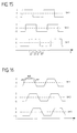
- Fig. 15
- eine Darstellung des Zeitverlaufs der in den drei Stromkreisen fließenden Ströme gemäß einer ersten Möglichkeit;
- Fig. 16
- eine schematische Darstellung des Zeitverlaufs des Stroms der in allen drei Stromkreisen verlaufenden Ströme über der Zeitachse gemäß der bevorzugten Ausführungsform;
- Fig. 17
- eine schematische Polygonschaltung für ein zweites Ausführungsbeispiel;
- Fig. 18
- eine schematische vereinfachte Darstellung der Durchschleifung zweier Teilwicklungen bei dem zweiten Ausführungsbeispiel und
- Fig. 19
- eine schematische Darstellung der Durchschleifung zweier Teilwicklungen bei einem dritten Ausführungsbeispiel gemäß Fig. 17.
Claims (46)
- Elektrische Maschine umfassenddadurch gekennzeichnet,ein Maschinengehäuse (40),einen in dem Maschinengehäuse (40) um eine Rotorachse (12) drehbar gelagerten Rotor (10),einen in dem Maschinengehäuse (40) angeordneten Stator (50), eine dem Stator (50) oder dem Rotor (10) zugeordnete Wicklung (60),und eine eine Felderzeugung in der Wicklung (60) steuernde Steuerschaltung mit einem Gleichstromzwischenkreis (108,110) und mindestens einem zwischen diesem und der Wicklung (60) angeordneten Leistungssteller (SB) sowie einer Ansteuerung (80) für den Leistungssteller, wobeialle die Felderzeugung in der Wicklung (60) steuernden Leistungssteller (SB) in dem Maschinengehäuse (40) angeordnet sind,daß die Wicklung (60) mindestens eine geradzahlige Anzahl N von vier oder mehr Teilwicklungen (S) umfaßt, wobei die Teilwicklungen (S) in Form einer Polygonschaltung so zusammengeschaltet sind, daß die Zahl der Ecken der Polygonschaltung der Zahl der Teilwicklungen (S) entspricht und jede Ecke ein Verknüpfungspunkt (V) von in der Polygonschaltung aufeinanderfolgenden Teilwicklungen (S) darstellt, so daß jeweils zwischen zwei aufeinanderfolgenden Verknüpfungspunkten (V) je eine Teilwicklung liegt,daß jeder Verknüpfungspunkt (V) einen Speiseanschluß (SP) aufweist, wobei die Speiseanschlüsse (SP) einander gegenüberliegender Verknüpfungspunkte (V) der Polygonschaltung ein Anschlußpaar bilden, zwischen welchem jeweils zwei parallel geschaltete Sätze (S1, S3, S5; S6, S4, S2) mit jeweils derselben Zahl hintereinandergeschalteter Teilwicklungen (S) liegen; unddaß die Anschlußpaare der Polygonschaltung in getrennten, durch mindestens einen der Leistungssteller (SB) gesteuerten Stromkreisen (SK1, SK2, SK3) liegen und jeder Stromkreis (SK1, SK2, SK3) einen sich periodisch ändernden und sich auf die beiden Sätze von Teilwicklungen verteilenden Strom durch die Wicklung fließen läßt.
- Maschine nach Anspruch 1, dadurch gekennzeichnet, daß die Wicklung (60) mehrere Stränge (S) aufweist und daß zur Steuerung der Felderzeugung in jedem Strang (S) für diesen mindestens ein Leistungssteller (SB) vorgesehen ist.
- Maschine nach Anspruch 1 oder 2, dadurch gekennzeichnet, daß die Leistungssteller (SB) einzeln um die Rotorachse (12) herum verteilt angeordnet sind.
- Maschine nach Anspruch 3, dadurch gekennzeichnet, daß die Leistungssteller (SB) in gleichen Winkelabständen um die Rotorachse (12) herum verteilt angeordnet sind.
- Maschine nach Anspruch 3 oder 4, dadurch gekennzeichnet, daß die Leistungssteller (SB) in gleichem radialen Abstand von der Rotorachse (12) angeordnet sind.
- Maschine nach einem der voranstehenden Ansprüche, dadurch gekennzeichnet, daß alle Leistungssteller (SB) an demselben Gleichstromzwischenkreis (108, 110) angeschlossen sind.
- Maschine nach Anspruch 6, dadurch gekennzeichnet, daß der Gleichstromzwischenkreis zwei um die Rotorachse (12) zumindest teilweise umlaufend angeordnete und parallel zueinander verlaufende Leiterbügel (108, 110) umfaßt, an welchen die Leistungssteller (SB) angeschlossen sind.
- Maschine nach Anspruch 7, dadurch gekennzeichnet, daß die Leiterbügel (108, 110) in einer senkrecht zur Rotorachse (12) verlaufenden Ebene (112) liegen.
- Maschine nach Anspruch 8, dadurch gekennzeichnet, daß die Leiterbügel (108, 110) als Flachleiter ausgebildet sind.
- Maschine nach einem der Ansprüche 7 bis 9, dadurch gekennzeichnet, daß die Leistungssteller (SB) Anschlüsse (120, 122) aufweisen, die direkt mit den Leiterbügeln (108, 110) verbunden sind.
- Maschine nach einem der Ansprüche 7 bis 10, dadurch gekennzeichnet, daß die Leiterbügel als Ringleiter (108, 110) ausgebildet sind.
- Maschine nach Anspruch 11, dadurch gekennzeichnet, daß die zwei Ringleiter (108, 110) konzentrisch zueinander angeordnet sind.
- Maschine nach einem der Ansprüche 8 bis 12, dadurch gekennzeichnet, daß die Leistungssteller (SB) auf einer Seite der Ebene (112) angeordnet sind, in welcher die Leiterbügel (108, 110) liegen.
- Maschine nach einem der Ansprüche 8 bis 13, dadurch gekennzeichnet, daß die Zwischenspeicherkondensatoren (140) im Maschinengehäuse (40) angeordnet sind.
- Maschine nach Anspruch 14, dadurch gekennzeichnet, daß jedem Leistungssteller (SB) ein Zwischenkreisspeicherkondensator (140) zugeordnet ist.
- Maschine nach Anspruch 14 oder 15, dadurch gekennzeichnet, daß auf der den Leistungsstellern (SB) gegenüberliegenden Seite der Ebene (112) die Zwischenkreisspeicherkondensatoren (140) sitzen.
- Maschine nach einem der voranstehenden Ansprüche, dadurch gekennzeichnet, daß die Stellersteuerung (80) im Maschinengehäuse (40) angeordnet ist.
- Maschine nach Anspruch 17, dadurch gekennzeichnet, daß die Stellersteuerung (80) nahe der Leistungssteller (SB) angeordnet ist.
- Maschine nach Anspruch 18, dadurch gekennzeichnet, daß die Stellersteuerung (80) in Zwischenräumen zwischen den Zwischenkreisspeicherkondensatoren (140) angeordnet ist.
- Maschine nach Anspruch 18 oder 19, dadurch gekennzeichnet, daß die Stellersteuerung (80) nahe der Leiterbügel (108, 110) sitzt.
- Maschine nach einem der voranstehenden Ansprüche, dadurch gekennzeichnet, daß die Leistungssteller (SB) gekühlt sind.
- Maschine nach Anspruch 21, dadurch gekennzeichnet, daß die Leistungssteller (SB) Kühlkörper (96) aufweisen.
- Maschine nach Anspruch 21 oder 22, dadurch gekennzeichnet, daß die Leistungssteller (SB) in thermischem Kontakt mit einem im Maschinengehäuse (40) angeordneten Kühlelement (87) stehen.
- Maschine nach Anspruch 23, dadurch gekennzeichnet, daß das Kühlelement (87) von dem flüssigen Kühlmedium durchströmt ist.
- Maschine nach Anspruch 24, dadurch gekennzeichnet, daß die Leistungssteller (SB) einen Kühlkörper (96) aufweisen, welcher in einen von dem flüssigen Kühlmedium durchströmten Kühlkanal (86) des Kühlelements (87) hineinragt.
- Maschine nach einem der Ansprüche 23 bis 25, dadurch gekennzeichnet, daß die Leistungssteller (SB) in dem Maschinengehäuse (40) von dem Kühlelement (87) gehalten sind.
- Maschine nach einem der Ansprüche 24 bis 26, dadurch gekennzeichnet, daß das Kühlelement (87) Teil des Maschinengehäuses (40) ist.
- Maschine nach Anspruch 27, dadurch gekennzeichnet, daß das Kühlelement durch einen Wandbereich des Maschinengehäuses (40) gebildet wird.
- Maschine nach einem der Ansprüche 25 bis 28, dadurch gekennzeichnet, daß der Leistungssteller eine Abdeckung (94) für eine Öffnung (100) des Kühlkanals (86) im Kühlelement (87) bildet.
- Maschine nach einem der Ansprüche 24 bis 29, dadurch gekennzeichnet, daß das Kühlelement (87) in einem Kühlungskreislauf des Stators (50) integriert ist.
- Maschine nach einem der voranstehenden Ansprüche, dadurch gekennzeichnet, daß die Wicklung (60) eine Statorwicklung ist.
- Maschine nach einem der voranstehenden Ansprüche, dadurch gekennzeichnet, daß die Leistungssteller (SB) zwischen dem Stator (50) und der Rotorachse (12) sitzen.
- Maschine nach einem der voranstehenden Ansprüche, dadurch gekennzeichnet, daß der Rotor (10) eine Kurzschlußwicklung aufweist.
- Maschine nach Anspruch 1, dadurch gekennzeichnet, daß sich in jedem Stromkreis (SK) der Strom (I) im wesent lichen gleichmäßig auf die beiden Sätze von Teilwicklungen (S) der Wicklung (60) verteilt.
- Maschine nach Anspruch 1 oder 34, dadurch gekennzeichnet, daß in der Polygonschaltung einander gegenüberliegende Teilwicklungen (S1, S2; S3, S5; S4, S6) im wesentlichen gleich ausgebildet sind.
- Maschine nach Anspruch 35, dadurch gekennzeichnet, daß alle Teilwicklungen (S) der Wicklung (60) im wesentlichen gleich ausgebildet sind.
- Maschine nach einem der Ansprüche 1, 34 bis 36, dadurch gekennzeichnet, daß Anfang (AS1, AS2 etc.) und Ende (ES1, ES2 etc.) in der Polygonschaltung aufeinanderfolgender Teilwicklungen (S1, S2, etc.) um ganzzahlige Zahlen von Polteilungen (62, 62') der Wicklung (60) gegeneinander versetzt angeordnet sind.
- Maschine nach Anspruch 37, dadurch gekennzeichnet, daß Anfang (AS1, AS2 etc.) und Ende (ES1, ES2 etc.) in der Polygonschaltung aufeinanderfolgender Teilwicklungen (S1, S2 etc.) um mindestens die ganzzahlige Zahl von Polteilungen (62, 62') der Wicklung (60) versetzt sind, die der nächst kleineren ganzen Zahl des Quotienten aus der Polzahl und der Zahl der Stränge (S) entspricht.
- Maschine nach Anspruch 37 oder 38, dadurch gekennzeichnet, daß Anfang (AS1, AS2 etc.) und Ende (ES1, ES2 etc.) in der Polygonschaltung aufeinanderfolgender Teilwicklungen (S1, S2 etc.) um höchstens die ganzzahlige Zahl von Polteilungen versetzt sind, die der nächst größeren ganzen Zahl des Quotienten aus Polzahl und Zahl der Stränge (S) entspricht.
- Maschine nach einem der Ansprüche 1, 34 bis 39, dadurch gekennzeichnet, daß jede Teilwicklung (S) der Wicklung (60) einen Strang bildet.
- Maschine nach einem der Ansprüche 1, 34 bis 39, dadurch gekennzeichnet, daß zwei in der Polygonschaltung einander gegenüberliegende Teilwicklungen (Sla, S1b, S2a, S2b etc.) einen Strang bilden.
- Maschine nach einem der Ansprüche 1, 34 bis 41, dadurch gekennzeichnet, daß die Ströme (I) in allen Stromkreisen (SK1, SK2, SK3) dieselbe Periodendauer aufweisen.
- Maschine nach einem der Ansprüche 1, 34 bis 42, dadurch gekennzeichnet, daß die Ströme (I) in allen Stromkreisen (SK1, SK2, SK3) dieselbe Halbwellenform aufweisen.
- Maschine nach einem der Ansprüche 1, 34 bis 43, dadurch gekennzeichnet, daß die Ströme (I) in allen Stromkreisen (SK1, SK2, SK3) im wesentlichen dieselbe Maximalamplitude aufweisen.
- Maschine nach einem der Ansprüche 1, 34 bis 44, dadurch gekennzeichnet, daß der sich periodisch ändernde Strom (I) in einem ausgewählten Stromkreis (SK1) gegenüber dem Strom in einem nächstliegenden Stromkreis (SK2, SK3) phasenverschoben ist.
- Maschine nach einem der Ansprüche 1, 34 bis 45, dadurch gekennzeichnet, daß in jedem Stromkreis (SK1, SK2, SK3) an jedem Speiseanschluß (SP1, SP2, SP3, SP4, SP5, SP6) ein Leistungssteller (SB1, SB2, SB3, SB4, SB5, SB6) vorgesehen ist und daß die beiden Leistungssteller (SB1, SB2, SB3, SB4, SBS, SB6) in jedem Stromkreis (SK1, SK2, SK3) durch eine gemeinsame Stellersteuerung (80) angesteuert sind.
Applications Claiming Priority (3)
| Application Number | Priority Date | Filing Date | Title |
|---|---|---|---|
| DE4422623A DE4422623A1 (de) | 1994-06-28 | 1994-06-28 | Elektrische Maschine |
| DE4422623 | 1994-06-28 | ||
| PCT/EP1995/002508 WO1996001001A2 (de) | 1994-06-28 | 1995-06-28 | Elektrische maschine |
Publications (2)
| Publication Number | Publication Date |
|---|---|
| EP0720785A1 EP0720785A1 (de) | 1996-07-10 |
| EP0720785B1 true EP0720785B1 (de) | 2001-10-24 |
Family
ID=6521730
Family Applications (1)
| Application Number | Title | Priority Date | Filing Date |
|---|---|---|---|
| EP95924947A Expired - Lifetime EP0720785B1 (de) | 1994-06-28 | 1995-06-28 | Elektrische maschine |
Country Status (7)
| Country | Link |
|---|---|
| EP (1) | EP0720785B1 (de) |
| AT (1) | ATE207670T1 (de) |
| DE (2) | DE4422623A1 (de) |
| DK (1) | DK0720785T3 (de) |
| ES (1) | ES2166826T3 (de) |
| PT (1) | PT720785E (de) |
| WO (1) | WO1996001001A2 (de) |
Families Citing this family (3)
| Publication number | Priority date | Publication date | Assignee | Title |
|---|---|---|---|---|
| EP1372247A1 (de) * | 2002-06-14 | 2003-12-17 | ABB Research Ltd. | Rotierende elektrische Maschine |
| JP4147987B2 (ja) * | 2003-03-17 | 2008-09-10 | 株式会社日立製作所 | 多相式交流回転電機 |
| JP3743433B2 (ja) | 2003-03-25 | 2006-02-08 | 日産自動車株式会社 | 電力変換装置 |
Family Cites Families (4)
| Publication number | Priority date | Publication date | Assignee | Title |
|---|---|---|---|---|
| US3506898A (en) * | 1966-11-07 | 1970-04-14 | Skil Corp | Stator construction including an encapsulated semi-conductor device mounted on the stator |
| DE1638415C3 (de) * | 1967-09-29 | 1978-06-01 | Licentia Patent-Verwaltungs-Gmbh, 6000 Frankfurt | Elektrischer Drehstrommotor, insbesondere Asynchronmotor, zum Antrieb einer überwiegend in einem bestimmten Teildrehzahlbereich betriebenen Arbeitsmaschine |
| GB2251522A (en) * | 1990-12-07 | 1992-07-08 | Ist Lab Ltd | An electric motor |
| GB9027449D0 (en) * | 1990-12-19 | 1991-02-06 | Duck Edward W | Skin care composition |
-
1994
- 1994-06-28 DE DE4422623A patent/DE4422623A1/de not_active Withdrawn
-
1995
- 1995-06-28 WO PCT/EP1995/002508 patent/WO1996001001A2/de not_active Ceased
- 1995-06-28 ES ES95924947T patent/ES2166826T3/es not_active Expired - Lifetime
- 1995-06-28 EP EP95924947A patent/EP0720785B1/de not_active Expired - Lifetime
- 1995-06-28 DE DE59509747T patent/DE59509747D1/de not_active Expired - Lifetime
- 1995-06-28 DK DK95924947T patent/DK0720785T3/da active
- 1995-06-28 PT PT95924947T patent/PT720785E/pt unknown
- 1995-06-28 AT AT95924947T patent/ATE207670T1/de not_active IP Right Cessation
Also Published As
| Publication number | Publication date |
|---|---|
| ES2166826T3 (es) | 2002-05-01 |
| WO1996001001A3 (de) | 1996-03-07 |
| DK0720785T3 (da) | 2002-02-18 |
| WO1996001001A2 (de) | 1996-01-11 |
| ATE207670T1 (de) | 2001-11-15 |
| PT720785E (pt) | 2002-04-29 |
| DE4422623A1 (de) | 1996-01-04 |
| DE59509747D1 (de) | 2001-11-29 |
| EP0720785A1 (de) | 1996-07-10 |
Similar Documents
| Publication | Publication Date | Title |
|---|---|---|
| EP3134960B1 (de) | Elektrische maschine | |
| EP3504780B1 (de) | Helixartige wicklung mit homogenerer feldausnutzung | |
| DE102014223202A1 (de) | Wellenwicklung, Stator und elektrische Maschine | |
| DE2629642A1 (de) | Polumschaltbare dreiphasenwicklung | |
| DE2506573B1 (de) | Polumschaltbare drehstromwicklung | |
| DE112013001755T5 (de) | Rotierende elektrische Maschine | |
| DE102004055317A1 (de) | Elektrische Drehfeldmaschine und Primärteil | |
| EP0243425B1 (de) | Stromrichtergespeiste synchronmaschine mit permanentmagnet-erregung | |
| DE112018000320T5 (de) | Antriebsvorrichtung | |
| WO2018002128A1 (de) | Rotor, verfahren zum herstellen eines rotors, reluktanzmaschine und arbeitsmaschine | |
| EP0715778B1 (de) | Asynchronmaschine | |
| DE112021001240T5 (de) | Stator mit spulenstruktur aus verteilten wicklungen und dreiphasiger wechselstrommotor mit diesem stator | |
| EP0720785B1 (de) | Elektrische maschine | |
| DE2757123A1 (de) | Wechselstromspeisevorrichtung und drehfeldgenerator mit einer wechselstromspeisevorrichtung | |
| DE19639670C2 (de) | Transversalflußmaschine mit einer Mehrzahl von parallel geschalteten Ringwicklungen | |
| WO2007077237A1 (de) | Generator, insbesondere für kraftfahrzeuge | |
| DE112016007043B4 (de) | Polzahl-verändernde rotierende elektrische maschine und antriebsverfahren für polzahl-verändernde rotierende elektrische maschine | |
| DE102020107636A1 (de) | Leistungselektronik-antrieb für eine zykloidale elektrischemaschine | |
| EP0833429A1 (de) | Transversalflussmaschine mit einer Mehrzahl von parallel geschalteten Ringwicklungen sowie Schaltungsanordnung zur Speisung der Transversalflussmaschine | |
| DE102024204137B4 (de) | Verteilte Wicklung für eine elektrische Maschine | |
| DE2727471C3 (de) | Elektronisch kommutierter Reluktanzmotor | |
| DE102016220044A1 (de) | Helixartige Wicklung mit erhöhter Feldausnutzung | |
| DE112022004572B4 (de) | Motor | |
| EP1618646A1 (de) | Mehrphasiger, vielpoliger, schnelllaufender linear- oder rotationssynchronmotor | |
| DE3428888A1 (de) | Drehfelderregte stromrichtermaschine |
Legal Events
| Date | Code | Title | Description |
|---|---|---|---|
| PUAI | Public reference made under article 153(3) epc to a published international application that has entered the european phase |
Free format text: ORIGINAL CODE: 0009012 |
|
| 17P | Request for examination filed |
Effective date: 19960326 |
|
| AK | Designated contracting states |
Kind code of ref document: A1 Designated state(s): AT BE DE DK ES FR GB GR IE IT LU NL PT SE |
|
| 17Q | First examination report despatched |
Effective date: 19980318 |
|
| RAP1 | Party data changed (applicant data changed or rights of an application transferred) |
Owner name: FIRMA EUGENIE MUEHMEL |
|
| GRAG | Despatch of communication of intention to grant |
Free format text: ORIGINAL CODE: EPIDOS AGRA |
|
| GRAG | Despatch of communication of intention to grant |
Free format text: ORIGINAL CODE: EPIDOS AGRA |
|
| GRAG | Despatch of communication of intention to grant |
Free format text: ORIGINAL CODE: EPIDOS AGRA |
|
| GRAH | Despatch of communication of intention to grant a patent |
Free format text: ORIGINAL CODE: EPIDOS IGRA |
|
| GRAH | Despatch of communication of intention to grant a patent |
Free format text: ORIGINAL CODE: EPIDOS IGRA |
|
| GRAA | (expected) grant |
Free format text: ORIGINAL CODE: 0009210 |
|
| AK | Designated contracting states |
Kind code of ref document: B1 Designated state(s): AT BE DE DK ES FR GB GR IE IT LU NL PT SE |
|
| REF | Corresponds to: |
Ref document number: 207670 Country of ref document: AT Date of ref document: 20011115 Kind code of ref document: T |
|
| REG | Reference to a national code |
Ref country code: IE Ref legal event code: FG4D Free format text: GERMAN |
|
| REF | Corresponds to: |
Ref document number: 59509747 Country of ref document: DE Date of ref document: 20011129 |
|
| REG | Reference to a national code |
Ref country code: GB Ref legal event code: IF02 |
|
| REG | Reference to a national code |
Ref country code: DK Ref legal event code: T3 |
|
| GBT | Gb: translation of ep patent filed (gb section 77(6)(a)/1977) |
Effective date: 20020206 |
|
| ET | Fr: translation filed | ||
| REG | Reference to a national code |
Ref country code: PT Ref legal event code: SC4A Free format text: AVAILABILITY OF NATIONAL TRANSLATION Effective date: 20020123 |
|
| REG | Reference to a national code |
Ref country code: ES Ref legal event code: FG2A Ref document number: 2166826 Country of ref document: ES Kind code of ref document: T3 |
|
| REG | Reference to a national code |
Ref country code: GR Ref legal event code: EP Ref document number: 20020400346 Country of ref document: GR |
|
| PLBE | No opposition filed within time limit |
Free format text: ORIGINAL CODE: 0009261 |
|
| STAA | Information on the status of an ep patent application or granted ep patent |
Free format text: STATUS: NO OPPOSITION FILED WITHIN TIME LIMIT |
|
| 26N | No opposition filed | ||
| PGFP | Annual fee paid to national office [announced via postgrant information from national office to epo] |
Ref country code: PT Payment date: 20091230 Year of fee payment: 16 |
|
| PGFP | Annual fee paid to national office [announced via postgrant information from national office to epo] |
Ref country code: IE Payment date: 20101210 Year of fee payment: 16 Ref country code: DK Payment date: 20101220 Year of fee payment: 16 Ref country code: AT Payment date: 20101214 Year of fee payment: 16 |
|
| PGFP | Annual fee paid to national office [announced via postgrant information from national office to epo] |
Ref country code: LU Payment date: 20101214 Year of fee payment: 16 |
|
| PGFP | Annual fee paid to national office [announced via postgrant information from national office to epo] |
Ref country code: GB Payment date: 20101210 Year of fee payment: 16 Ref country code: NL Payment date: 20101230 Year of fee payment: 16 Ref country code: IT Payment date: 20101216 Year of fee payment: 16 Ref country code: GR Payment date: 20101229 Year of fee payment: 16 Ref country code: SE Payment date: 20101221 Year of fee payment: 16 |
|
| PGFP | Annual fee paid to national office [announced via postgrant information from national office to epo] |
Ref country code: FR Payment date: 20110119 Year of fee payment: 16 |
|
| PGFP | Annual fee paid to national office [announced via postgrant information from national office to epo] |
Ref country code: BE Payment date: 20101224 Year of fee payment: 16 Ref country code: ES Payment date: 20101213 Year of fee payment: 16 |
|
| BERE | Be: lapsed |
Owner name: FIRMA EUGENIE *MUHMEL Effective date: 20110630 |
|
| REG | Reference to a national code |
Ref country code: PT Ref legal event code: MM4A Free format text: LAPSE DUE TO NON-PAYMENT OF FEES Effective date: 20111228 |
|
| REG | Reference to a national code |
Ref country code: NL Ref legal event code: V1 Effective date: 20120101 |
|
| PG25 | Lapsed in a contracting state [announced via postgrant information from national office to epo] |
Ref country code: PT Free format text: LAPSE BECAUSE OF NON-PAYMENT OF DUE FEES Effective date: 20111228 |
|
| REG | Reference to a national code |
Ref country code: DK Ref legal event code: EBP |
|
| REG | Reference to a national code |
Ref country code: SE Ref legal event code: EUG |
|
| GBPC | Gb: european patent ceased through non-payment of renewal fee |
Effective date: 20110628 |
|
| PG25 | Lapsed in a contracting state [announced via postgrant information from national office to epo] |
Ref country code: AT Free format text: LAPSE BECAUSE OF NON-PAYMENT OF DUE FEES Effective date: 20110628 Ref country code: IT Free format text: LAPSE BECAUSE OF NON-PAYMENT OF DUE FEES Effective date: 20110628 |
|
| REG | Reference to a national code |
Ref country code: GR Ref legal event code: ML Ref document number: 20020400346 Country of ref document: GR Effective date: 20120105 |
|
| REG | Reference to a national code |
Ref country code: AT Ref legal event code: MM01 Ref document number: 207670 Country of ref document: AT Kind code of ref document: T Effective date: 20110628 |
|
| REG | Reference to a national code |
Ref country code: FR Ref legal event code: ST Effective date: 20120229 |
|
| REG | Reference to a national code |
Ref country code: IE Ref legal event code: MM4A |
|
| PG25 | Lapsed in a contracting state [announced via postgrant information from national office to epo] |
Ref country code: BE Free format text: LAPSE BECAUSE OF NON-PAYMENT OF DUE FEES Effective date: 20110630 |
|
| PG25 | Lapsed in a contracting state [announced via postgrant information from national office to epo] |
Ref country code: IE Free format text: LAPSE BECAUSE OF NON-PAYMENT OF DUE FEES Effective date: 20110628 Ref country code: FR Free format text: LAPSE BECAUSE OF NON-PAYMENT OF DUE FEES Effective date: 20110630 |
|
| PG25 | Lapsed in a contracting state [announced via postgrant information from national office to epo] |
Ref country code: NL Free format text: LAPSE BECAUSE OF NON-PAYMENT OF DUE FEES Effective date: 20120101 Ref country code: GR Free format text: LAPSE BECAUSE OF NON-PAYMENT OF DUE FEES Effective date: 20120105 |
|
| PG25 | Lapsed in a contracting state [announced via postgrant information from national office to epo] |
Ref country code: GB Free format text: LAPSE BECAUSE OF NON-PAYMENT OF DUE FEES Effective date: 20110628 |
|
| PG25 | Lapsed in a contracting state [announced via postgrant information from national office to epo] |
Ref country code: DK Free format text: LAPSE BECAUSE OF NON-PAYMENT OF DUE FEES Effective date: 20110630 |
|
| REG | Reference to a national code |
Ref country code: ES Ref legal event code: FD2A Effective date: 20121116 |
|
| PG25 | Lapsed in a contracting state [announced via postgrant information from national office to epo] |
Ref country code: ES Free format text: LAPSE BECAUSE OF NON-PAYMENT OF DUE FEES Effective date: 20110629 |
|
| PG25 | Lapsed in a contracting state [announced via postgrant information from national office to epo] |
Ref country code: SE Free format text: LAPSE BECAUSE OF NON-PAYMENT OF DUE FEES Effective date: 20110629 |
|
| PG25 | Lapsed in a contracting state [announced via postgrant information from national office to epo] |
Ref country code: LU Free format text: LAPSE BECAUSE OF NON-PAYMENT OF DUE FEES Effective date: 20110628 |
|
| PGFP | Annual fee paid to national office [announced via postgrant information from national office to epo] |
Ref country code: DE Payment date: 20131210 Year of fee payment: 19 |
|
| REG | Reference to a national code |
Ref country code: DE Ref legal event code: R119 Ref document number: 59509747 Country of ref document: DE |
|
| REG | Reference to a national code |
Ref country code: DE Ref legal event code: R119 Ref document number: 59509747 Country of ref document: DE Effective date: 20150101 |
|
| PG25 | Lapsed in a contracting state [announced via postgrant information from national office to epo] |
Ref country code: DE Free format text: LAPSE BECAUSE OF NON-PAYMENT OF DUE FEES Effective date: 20150101 |