EP0720865A1 - Dispositif de déchiquetage - Google Patents
Dispositif de déchiquetage Download PDFInfo
- Publication number
- EP0720865A1 EP0720865A1 EP95200024A EP95200024A EP0720865A1 EP 0720865 A1 EP0720865 A1 EP 0720865A1 EP 95200024 A EP95200024 A EP 95200024A EP 95200024 A EP95200024 A EP 95200024A EP 0720865 A1 EP0720865 A1 EP 0720865A1
- Authority
- EP
- European Patent Office
- Prior art keywords
- shredding
- housing
- discharge opening
- carrier member
- opening
- Prior art date
- Legal status (The legal status is an assumption and is not a legal conclusion. Google has not performed a legal analysis and makes no representation as to the accuracy of the status listed.)
- Withdrawn
Links
- 239000000463 material Substances 0.000 claims abstract description 10
- 238000007599 discharging Methods 0.000 claims abstract description 3
- 238000005265 energy consumption Methods 0.000 description 2
- 230000003247 decreasing effect Effects 0.000 description 1
- 230000001419 dependent effect Effects 0.000 description 1
- 238000005728 strengthening Methods 0.000 description 1
Images

Classifications
-
- B—PERFORMING OPERATIONS; TRANSPORTING
- B02—CRUSHING, PULVERISING, OR DISINTEGRATING; PREPARATORY TREATMENT OF GRAIN FOR MILLING
- B02C—CRUSHING, PULVERISING, OR DISINTEGRATING IN GENERAL; MILLING GRAIN
- B02C19/00—Other disintegrating devices or methods
- B02C19/0056—Other disintegrating devices or methods specially adapted for specific materials not otherwise provided for
- B02C19/0081—Other disintegrating devices or methods specially adapted for specific materials not otherwise provided for specially adapted for breaking-up bottles
-
- B—PERFORMING OPERATIONS; TRANSPORTING
- B02—CRUSHING, PULVERISING, OR DISINTEGRATING; PREPARATORY TREATMENT OF GRAIN FOR MILLING
- B02C—CRUSHING, PULVERISING, OR DISINTEGRATING IN GENERAL; MILLING GRAIN
- B02C18/00—Disintegrating by knives or other cutting or tearing members which chop material into fragments
- B02C18/06—Disintegrating by knives or other cutting or tearing members which chop material into fragments with rotating knives
- B02C18/08—Disintegrating by knives or other cutting or tearing members which chop material into fragments with rotating knives within vertical containers
- B02C18/086—Disintegrating by knives or other cutting or tearing members which chop material into fragments with rotating knives within vertical containers specially adapted for disintegrating plastics, e.g. cinematographic films
-
- B—PERFORMING OPERATIONS; TRANSPORTING
- B02—CRUSHING, PULVERISING, OR DISINTEGRATING; PREPARATORY TREATMENT OF GRAIN FOR MILLING
- B02C—CRUSHING, PULVERISING, OR DISINTEGRATING IN GENERAL; MILLING GRAIN
- B02C18/00—Disintegrating by knives or other cutting or tearing members which chop material into fragments
- B02C18/06—Disintegrating by knives or other cutting or tearing members which chop material into fragments with rotating knives
- B02C18/08—Disintegrating by knives or other cutting or tearing members which chop material into fragments with rotating knives within vertical containers
- B02C18/12—Disintegrating by knives or other cutting or tearing members which chop material into fragments with rotating knives within vertical containers with drive arranged below container
Definitions
- the invention relates to a device for reducing in size of particularly plastic objects.
- Such devices are already generally known and are often designated with the collective name of "shredders”.
- the invention has for its object to provide a shredding device with a decreased energy consumption and increased level of performance relative to the known devices.
- the invention provides a device for shredding particularly plastic objects, provided with a substantially cylindrical housing in which at least one carrier member is rotatably mounted, wherein the housing has at least one opening arranged in one of its end surfaces for feeding objects for shredding and at least one opening arranged in its side surface for discharging shredded material, which discharge opening is bounded by a cutting edge.
- the products for shredding after having been placed into the housing through the feed opening, are urged to the outside of the housing by the centrifugal force resulting from the rotation of the carrier member and subsequently pressed against the cutting edge of the discharge opening and thereby shredded.
- the shredded material is ejected with force from the housing through the discharge opening. A clean cutting action is thus obtained whereby the energy required for the shredding is minimal and the performance level of the device maximal.
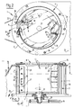
- a device 1 for shredding objects 2, in particular hollow plastic articles, is provided with a substantially cylindrical housing 3 in which in which a carrier member 4 is rotatably mounted.
- the housing 3 is formed by an upper surface 5, a lower surface 6 and a substantially cylindrical side surface 7.
- the upper surface 5 and the lower surface 6 are further connected by a number of mutually spaced strengthening rods 30.
- Arranged in the upper surface 5 is a feed opening 8 bounded by a ring 15 for the objects 2 for shredding.
- the housing 3 has in its side wall 7 a discharge opening 9 for shredded material 10 which is bounded by a cutting edge 11.
- Discharge opening 9 is slit-shaped and runs parallel to a generating line of the side wall.
- the discharge opening 9, which covers practically the whole height of housing 3, is formed by the housing 3 taking the form of a spiral with a diameter which increases from the cutting edge 11 in the rotation direction R of carrier member 4.
- the discharge opening 9 is covered by a hood 23 which intercepts the shredded material 10 flung with force out of housing 3.
- the carrier member 4 is formed by a circular supporting disc 13 on which two anvils 12 are arranged with equal interspacing.
- Carrier member 4 has on its underside a shaft 21 on which a pulley 20 is arranged and driven rotatably by a motor 16, the output shaft 17 of which is likewise provided with a pulley 18.
- Three drive belts 19 stretch between the two pulleys 18,20.
- motor 16 is arranged on a support frame 22.
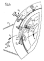
- the anvils 12 are each substantially L-shaped in cross section and provided on their leading surface 29 as seen in rotation direction R with an exchangeable stop strip 27 fastened by bolts 28.
- the bolts 28 are received in slot-like apertures 31 of the striker strip 27, whereby the position of striker strip 27 can be varied relative to the leading surface 29.
- this edge is formed by a replaceable cutting blade 26 which is fastened by means of bolts 24 to a receiving block 25 connected to the side wall 7 of the housing.
- the objects 2 for shredding are thrown as according to arrow S into the feed opening 8 on the top side of housing 3, whereafter they are urged toward the side wall 7 of the housing by the centrifugal force acting in housing 3 as a result of the rotation of the carrier member 4. They are herein carried along the wall 7 by the anvils 12 of carrier member 4.
- the wall 7 has a spiral-shaped progression (fig. 2) with a diameter which increases from the cutting edge 11 in the rotation direction R.
- the slit-like aperture 9 is hereby defined between the cutting wall 11 and the end of the wall 7 located opposite.
- the objects 2 for shredding are urged along wall 7 by anvils 12 until they reach cutting edge 11, whereafter through co-action between the cutting edge 11 and the striker strip 27 of anvil 12 a portion of the objects 2 for shredding is severed and ejected as shredded material 10 from housing 3 in the direction of arrow D. In this manner a clean and very efficient cutting movement is effected, whereby a uniform shredding of objects 2 is achieved with minimal energy consumption.
- the discharge opening 9 can take an adjustable form.
- the outer wall part 14 which bounds opening 9 can take a hinged form and be connected to a screw adjustment mechanism 35.
- the wall part 14 can thus be pivoted round a pivot shaft 34 between for instance the position shown in full lines and the position 14' shown in dashed lines in order to adjust the desired discharge opening 9.
- the carrier member 4 can also be provided with more than two anvils which, in order to obtain uniform running of the device, must preferably be arranged at equal mutual angular distances. It is optionally also possible to arrange more than one discharge opening in the wall, or to divide the discharge opening in height direction with horizontal blades.
- the device which in the illustrated embodiment is shown in standing position, can also be placed in lying position as long as the rotation speed of carrier member 4 is sufficient to urge the objects for shredding to the spiral-shaped wall by centrifugal force.
Landscapes
- Engineering & Computer Science (AREA)
- Food Science & Technology (AREA)
- Crushing And Pulverization Processes (AREA)
Priority Applications (3)
| Application Number | Priority Date | Filing Date | Title |
|---|---|---|---|
| EP95200024A EP0720865A1 (fr) | 1995-01-06 | 1995-01-06 | Dispositif de déchiquetage |
| US08/583,647 US5687921A (en) | 1995-01-06 | 1996-01-05 | Reducing apparatus |
| JP8000741A JPH08229426A (ja) | 1995-01-06 | 1996-01-08 | 細断装置 |
Applications Claiming Priority (1)
| Application Number | Priority Date | Filing Date | Title |
|---|---|---|---|
| EP95200024A EP0720865A1 (fr) | 1995-01-06 | 1995-01-06 | Dispositif de déchiquetage |
Publications (1)
| Publication Number | Publication Date |
|---|---|
| EP0720865A1 true EP0720865A1 (fr) | 1996-07-10 |
Family
ID=8219946
Family Applications (1)
| Application Number | Title | Priority Date | Filing Date |
|---|---|---|---|
| EP95200024A Withdrawn EP0720865A1 (fr) | 1995-01-06 | 1995-01-06 | Dispositif de déchiquetage |
Country Status (3)
| Country | Link |
|---|---|
| US (1) | US5687921A (fr) |
| EP (1) | EP0720865A1 (fr) |
| JP (1) | JPH08229426A (fr) |
Cited By (3)
| Publication number | Priority date | Publication date | Assignee | Title |
|---|---|---|---|---|
| CN108787079A (zh) * | 2018-05-24 | 2018-11-13 | 肖建平 | 一种家电生产用废弃塑料外壳破碎装置 |
| CN114160276A (zh) * | 2021-11-08 | 2022-03-11 | 江苏大学镇江流体工程装备技术研究院 | 一种应用于渣浆泵的多重固液分离破碎装置 |
| CN114377803A (zh) * | 2022-01-12 | 2022-04-22 | 杨振宙 | 一种中药破壁的破碎设备 |
Families Citing this family (6)
| Publication number | Priority date | Publication date | Assignee | Title |
|---|---|---|---|---|
| DE50004302D1 (de) * | 1999-02-11 | 2003-12-11 | Bucher Guyer Ag Masch | Vorrichtung zum zerreissen von früchten |
| US20090090800A1 (en) * | 2007-10-05 | 2009-04-09 | Vermeer Manufacturing Company | Method and apparatus for shaped openings in a grinder screen |
| DE102013108292A1 (de) * | 2013-08-01 | 2015-02-05 | Claas Selbstfahrende Erntemaschinen Gmbh | Mähdrescher mit einer Häckselvorrichtung |
| US9821485B2 (en) * | 2013-09-16 | 2017-11-21 | Vanmark Equipment, Llc | Rotating cutting blade assembly |
| US10456943B2 (en) * | 2014-12-03 | 2019-10-29 | Urschel Laboratories, Inc. | Machines and methods for cutting products and impellers therefor |
| BE1023152B1 (nl) | 2015-08-28 | 2016-12-02 | Cnh Industrial Belgium Nv | Oogstmachine met feedbackregeling van hakselparameters |
Citations (6)
| Publication number | Priority date | Publication date | Assignee | Title |
|---|---|---|---|---|
| GB416287A (en) * | 1934-04-09 | 1934-09-13 | Batchelor Robinson & Company L | A machine for use in the crushing, piercing and mixing of metallic containers, tinplates or terne or lead coated plates or strips or the like |
| US3353755A (en) * | 1964-04-20 | 1967-11-21 | Alpine Ag | Cutting mill |
| GB1292493A (en) * | 1970-02-25 | 1972-10-11 | Commercial Holdings Ltd | Glass pulverising apparatus |
| DE2153236A1 (de) * | 1971-10-26 | 1973-05-10 | Alfred Fritsch Ohg | Muehle |
| DE2827349A1 (de) * | 1978-06-22 | 1980-01-10 | Jupiter Gmbh Kuechenmaschf | Muehle zum zerkleinern von stueckigem und koernigem gut, wie nuesse, mandeln o.dgl. |
| EP0220100A2 (fr) * | 1985-10-03 | 1987-04-29 | Commissariat A L'energie Atomique | Broyeur démontable pour petits objets de verre ou en plastique rigide |
Family Cites Families (8)
| Publication number | Priority date | Publication date | Assignee | Title |
|---|---|---|---|---|
| US2195879A (en) * | 1937-12-22 | 1940-04-02 | William E Urschel | Slicing machine |
| GB651920A (en) * | 1947-05-27 | 1951-04-11 | Aage Georg Jorgensen | Slicing machine for household use |
| US2961024A (en) * | 1958-02-13 | 1960-11-22 | Joe R Urschel | Chamber for centrifugal slicing machine |
| US4055099A (en) * | 1975-02-28 | 1977-10-25 | Chubukoki Kabushiki Kaisha | Food slicer |
| US3989196A (en) * | 1975-04-09 | 1976-11-02 | Urschel Joe R | Cutter head |
| US4648296A (en) * | 1984-11-26 | 1987-03-10 | Frito-Lay Inc. | Method and apparatus for feeding slicers |
| US4858834A (en) * | 1988-01-11 | 1989-08-22 | Beloit Corporation | Chip slicer improvement |
| US4972888A (en) * | 1989-11-14 | 1990-11-27 | Acrowood Corporation | Blade-carrying drum assembly for chip slicing machines |
-
1995
- 1995-01-06 EP EP95200024A patent/EP0720865A1/fr not_active Withdrawn
-
1996
- 1996-01-05 US US08/583,647 patent/US5687921A/en not_active Expired - Fee Related
- 1996-01-08 JP JP8000741A patent/JPH08229426A/ja active Pending
Patent Citations (6)
| Publication number | Priority date | Publication date | Assignee | Title |
|---|---|---|---|---|
| GB416287A (en) * | 1934-04-09 | 1934-09-13 | Batchelor Robinson & Company L | A machine for use in the crushing, piercing and mixing of metallic containers, tinplates or terne or lead coated plates or strips or the like |
| US3353755A (en) * | 1964-04-20 | 1967-11-21 | Alpine Ag | Cutting mill |
| GB1292493A (en) * | 1970-02-25 | 1972-10-11 | Commercial Holdings Ltd | Glass pulverising apparatus |
| DE2153236A1 (de) * | 1971-10-26 | 1973-05-10 | Alfred Fritsch Ohg | Muehle |
| DE2827349A1 (de) * | 1978-06-22 | 1980-01-10 | Jupiter Gmbh Kuechenmaschf | Muehle zum zerkleinern von stueckigem und koernigem gut, wie nuesse, mandeln o.dgl. |
| EP0220100A2 (fr) * | 1985-10-03 | 1987-04-29 | Commissariat A L'energie Atomique | Broyeur démontable pour petits objets de verre ou en plastique rigide |
Cited By (4)
| Publication number | Priority date | Publication date | Assignee | Title |
|---|---|---|---|---|
| CN108787079A (zh) * | 2018-05-24 | 2018-11-13 | 肖建平 | 一种家电生产用废弃塑料外壳破碎装置 |
| CN114160276A (zh) * | 2021-11-08 | 2022-03-11 | 江苏大学镇江流体工程装备技术研究院 | 一种应用于渣浆泵的多重固液分离破碎装置 |
| CN114377803A (zh) * | 2022-01-12 | 2022-04-22 | 杨振宙 | 一种中药破壁的破碎设备 |
| CN114377803B (zh) * | 2022-01-12 | 2023-08-04 | 江西奉原生态科技有限公司 | 一种中药破壁的破碎设备 |
Also Published As
| Publication number | Publication date |
|---|---|
| US5687921A (en) | 1997-11-18 |
| JPH08229426A (ja) | 1996-09-10 |
Similar Documents
| Publication | Publication Date | Title |
|---|---|---|
| US5462238A (en) | Apparatus and method for shredding insulation | |
| EP1525057B1 (fr) | Dispositif de broyage industriel a double corps | |
| US5556042A (en) | Combine chopper attachment with pivotal broadcast discharge chute | |
| US4625606A (en) | Rotary cutting apparatus | |
| US5687921A (en) | Reducing apparatus | |
| US4087051A (en) | Comminuting apparatus | |
| US4231495A (en) | Rotary feeder for pneumatic conveying line | |
| US6390397B1 (en) | Paper shredding device | |
| US3674220A (en) | Chipper shredder | |
| GB1588237A (en) | Apparatus for the comminution of waste materials particularly industrial waste and bulk refuse | |
| EP1585381B1 (fr) | Dispositif servant a manipuler des balles de foin | |
| US5470182A (en) | Envelope opening machine | |
| US3974725A (en) | High volume cutter for elongate food products | |
| US4712458A (en) | Food loaf slicing machine with improved stacking characteristics | |
| US4594841A (en) | Forage cutter or chopper | |
| JP3597804B2 (ja) | 食品細断装置 | |
| US4240588A (en) | Wood chipping installation | |
| US5427162A (en) | Wood shaver | |
| US4760967A (en) | Mulcher-chopper | |
| JP3584223B2 (ja) | 破砕装置 | |
| US3831475A (en) | Comestible slicing apparatus | |
| US4913017A (en) | Meat cutting device | |
| US3027925A (en) | Rotary cutter having a vertically upward intake | |
| US3913431A (en) | Cutting machine for friction material | |
| US4538492A (en) | Bean cutter |
Legal Events
| Date | Code | Title | Description |
|---|---|---|---|
| PUAI | Public reference made under article 153(3) epc to a published international application that has entered the european phase |
Free format text: ORIGINAL CODE: 0009012 |
|
| AK | Designated contracting states |
Kind code of ref document: A1 Designated state(s): AT BE CH DE FR GB LI LU NL SE |
|
| RBV | Designated contracting states (corrected) |
Designated state(s): AT BE CH DE FR GB LI LU NL SE |
|
| 17P | Request for examination filed |
Effective date: 19961213 |
|
| STAA | Information on the status of an ep patent application or granted ep patent |
Free format text: STATUS: THE APPLICATION IS DEEMED TO BE WITHDRAWN |
|
| 18D | Application deemed to be withdrawn |
Effective date: 19990803 |