EP0720912A2 - Pflegevorrichtung in einem Tintenstrahldrucker - Google Patents
Pflegevorrichtung in einem Tintenstrahldrucker Download PDFInfo
- Publication number
- EP0720912A2 EP0720912A2 EP95309524A EP95309524A EP0720912A2 EP 0720912 A2 EP0720912 A2 EP 0720912A2 EP 95309524 A EP95309524 A EP 95309524A EP 95309524 A EP95309524 A EP 95309524A EP 0720912 A2 EP0720912 A2 EP 0720912A2
- Authority
- EP
- European Patent Office
- Prior art keywords
- cap
- carriage
- ink jet
- printing
- guide
- Prior art date
- Legal status (The legal status is an assumption and is not a legal conclusion. Google has not performed a legal analysis and makes no representation as to the accuracy of the status listed.)
- Granted
Links
Images


Classifications
-
- B—PERFORMING OPERATIONS; TRANSPORTING
- B41—PRINTING; LINING MACHINES; TYPEWRITERS; STAMPS
- B41J—TYPEWRITERS; SELECTIVE PRINTING MECHANISMS, i.e. MECHANISMS PRINTING OTHERWISE THAN FROM A FORME; CORRECTION OF TYPOGRAPHICAL ERRORS
- B41J2/00—Typewriters or selective printing mechanisms characterised by the printing or marking process for which they are designed
- B41J2/005—Typewriters or selective printing mechanisms characterised by the printing or marking process for which they are designed characterised by bringing liquid or particles selectively into contact with a printing material
- B41J2/01—Ink jet
- B41J2/135—Nozzles
- B41J2/165—Prevention or detection of nozzle clogging, e.g. cleaning, capping or moistening for nozzles
- B41J2/16517—Cleaning of print head nozzles
- B41J2/16535—Cleaning of print head nozzles using wiping constructions
- B41J2/16544—Constructions for the positioning of wipers
- B41J2/16547—Constructions for the positioning of wipers the wipers and caps or spittoons being on the same movable support
Definitions
- This invention relates to a maintenance device in an ink jet printing apparatus and, in particular, to a capping mechanism and a wiper arrangement in the maintenance device.
- the maintenance device in an ink jet printing apparatus is generally disposed at an end of the printing apparatus. Because printing cannot be performed in the area above the maintenance device, it is advantageous to minimize the size of the maintenance device to reduce the overall size of the printing apparatus and to increase a space where printing can be performed.
- a maintenance device in an ink jet printing apparatus generally performs maintenance operations to preserve the life of the ink jet head.
- the maintenance device includes a wiper for wiping residual ink from the nozzles of the ink jet head after completion of printing and a capping mechanism to cap the ink jet head for storage. The wiping and capping operations prevent the nozzles from becoming blocked and extend the life of the ink jet head.
- US-A-4,533,927 describes an ink jet system printer including a capping mechanism for covering a printer head when a carriage is located at a standby position.
- the capping mechanism includes a cap member supported by a slidable plate that is shifted toward the printer head as the printer head moves to the standby position through the use of links.
- the slidable plate is shifted by the traveling force of the carriage so that a separate drive source is not required.
- This patent relies on the use of a large number of parts and relies on springs to perform the capping action.
- this patent does not suggest a way to reduce a size of a maintenance device including a capping mechanism and a wiper.
- a maintenance device in an ink jet printing apparatus including: a movable cap carriage supporting a cap and including first and second guide pins, wherein the cap is engageable with an ink jet head of the ink jet printing apparatus; and a guide member including first and second guide slots receiving the first and second guide pins of the cap carriage, respectively, wherein the first and second guide slots are inclined at different angles.
- the cap carriage may be movable between a recessed position and an engaged position by the first and second guide pins in the first and second guide slots, wherein the first guide slot is configured such that the cap is disposed clear of a printing carriage path in the recessed position.
- the first guide slot may be inclined at a steeper angle than the second guide slot such that the cap carriage is shifted and rotated between the recessed position and the engaged position.
- the cap may be disposed substantially in alignment with the first guide pin.
- the movable cap carriage may further include third and fourth guide pins, and the guide member may further include third and fourth guide slots receiving the third and fourth guide pins.
- the cap may be telescopically slidable in an aperture through the movable cap carriage, and a spring may be disposed between the cap and the movable cap carriage, the spring causing the cap to seal around the ink jet head with a positive capping force when the cap is engaged with the ink jet head.
- an ink jet printing apparatus including: a printing carriage that is movable between a maintenance area and a printing area; a maintenance device including: a cap carriage movable between a recessed position and an engaged position and supporting a cap, the cap carriage including first and second guide pins, wherein the cap covers an ink jet head of the ink jet printing apparatus in the engaged position, a printing carriage engaging member attached to the cap carriage, the printing carriage engaging member engaging the printing carriage when the printing carriage moves between the printing area and the maintenance area, and a guide member including first and second guide slots receiving the first and second guide pins of the cap carriage, respectively; and a spring, one end of the spring fixed to a stationary portion of the ink jet printing apparatus and the other end of the spring fixed to the cap carriage for movement with the cap carriage, wherein the spring is disposed at an angle substantially corresponding to an incline angle of one of the first and second guide slots.
- a first of the two guide slots may be configured such that the cap is disposed clear of a printing carriage path in the recessed position, or a first of the two guide slots may be inclined at a steeper angle than an incline angle of a second of the two guide slots such that the cap carriage is shifted and rotated between the recessed position and the engaged position.
- the two guide slots may be inclined at different angles, and/or the spring may urge the cap carriage toward the recessed position.
- the cap may be telescopically slidable in an aperture through the movable cap carriage, and a spring may be disposed between the cap and the movable cap carriage, the spring causing the cap to seal around the ink jet head with a positive capping force in the engaged position.
- a maintenance device in an ink jet printing apparatus including a movable cap carriage supporting a cap, wherein the cap is engageable with an ink jet head of the ink jet printing apparatus, and structure for shifting the cap carriage between a recessed position and an engaged position and for reducing frictional resistance during shifting, wherein the cap covers an ink jet head of the ink jet printing apparatus in the engaged position.
- the shifting and reducing structure may comprise a plurality of guide pins fixed to one of the cap carriage and the guide member and a corresponding plurality of guide slots formed in the other of the cap carriage and the guide member, the guide slots receiving the guide pins, wherein the guide slots are inclined at different angles.
- a first of the guide slots may be configured such that the cap is disposed clear of a printing carriage path in the recessed position, or a first of the guide slots may be inclined at a steeper angle than a second of the guide slots such that the cap carriage is shifted and rotated between the recessed position and the engaged position.
- the cap may be telescopically slidable in an aperture through the movable cap carriage, and a spring may be disposed between the cap and the movable cap carriage, the spring causing the cap to seal around the ink jet head with a positive capping force in the engaged position.
- the shifting and reducing structure may include at least one slot having an incline angle, at least one pin fixed to the movable cap carriage, the at least one slot receiving the pin, and a spring attachable between the movable cap carriage and a stationary portion of the ink jet printing apparatus, the spring being disposed at an angle substantially corresponding to the incline angle of the at least one slot.
- an ink jet typewriter 10 of the present invention comprises a keyboard 12 and a liquid crystal display 14 for displaying typed text before it is printed on a recording medium.
- the liquid crystal display 14 is mounted on a cover 16 that is pivotable to various set positions according to user preference.
- the pivotable panel 16 includes a control mechanism 18 for varying the light intensity and/or contrast of the liquid crystal display 14.
- the typewriter 10 also may include all necessary mechanisms found on conventional machines, such as a manual paper advancement knob 19.
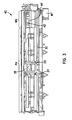
- Fig. 2 shows details of the paper guidance and conveying mechanism 20 in relation to the reciprocable printing mechanism 22.
- the reciprocable printing mechanism 22 includes a printing carriage 24 and a print cartridge 26 that is fitted onto the carriage 24 using a flexible tab mechanism 28.
- the carriage 24 and the cartridge 26, as an integral unit, are reciprocated along a main shaft 30.
- a print head 32 such as an ink jet print head having ink jet nozzles, prints characters onto a recording medium (not shown), such as cut sheet paper documents or other sheet material, which may have various thicknesses.
- the print head 32 is formed as an integral part of the cartridge 26.
- the maintenance device 40 for the printing apparatus is disposed at an end of the printing carriage travel path. Because printing cannot be carried out in the maintenance area, it is desirable to minimize the size of the maintenance device to thereby minimize the size of the printing apparatus and maximize a printing area.
- the printing carriage 24, during printing, is movable across a printing area PA by a driving force of a motor M transmitted by a timing belt (not shown).
- the printing apparatus can be of the type that prints in forward and reverse directions or either one thereof.
- the invention is not meant to be limited.
- the carriage is shifted to one end of the printing apparatus behind the printing area PA. This position is a maintenance area MA where the printing carriage 24 is disposed above the maintenance device 40.
- the structure of the invention enables the ink jet nozzles of the ink jet cartridge 26 to be wiped clean by a wiper 42 as the carriage 24 moves into the maintenance area and capped by a capping mechanism 44 when the printing carriage 24 is shifted from the printing area PA to the maintenance area MA.
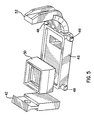
- Fig. 5 illustrates the components of the maintenance device 40.
- the maintenance device 40 includes a movable cap carriage 46 supporting a cap 50 and including four guide pins 48 (two pins 48 in one side of the cap carriage 46 can be seen in Fig. 5).
- the cap 50 is shaped to fit over the nozzles of the ink jet head 32.
- the maintenance device 40 also includes a wiper 42 for wiping residual ink from the nozzles of the ink jet head 32.
- the wiper 42 is preferably formed of a flexible material such as rubber.
- the wiper 42 is fixed in its position and is disposed in a traveling path of the print cartridge 26 to wipe residual ink from ink jet nozzles of the ink jet head 32 when the printing carriage 24 is moved from the printing area PA to the maintenance area MA.
- a printing carriage engaging member 52 is disposed at one end of the movable cap carriage 46. The printing carriage engaging member 52 engages the printing carriage 24 when the printing carriage 24 moves in the maintenance area MA and moves the cap 50 into the capping
- a cover 54 surrounds the components of the maintenance device 40.
- the cover 54 includes a first guide slot 56 and a second guide slot 58.
- the guide pins 48 are adapted to move in guide slots 56, 58 so that the first and second guide slots 56, 58 and the guide pins 48 operate in a cam and a cam follower like manner.
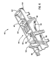
- the printing carriage 24 moves into the maintenance area MA, the printing carriage 24 abuts the printing carriage engaging member 52, which moves the cap carriage 46 with the guide pins 48 sliding in the guide slots 56, 58.
- the guide slots are inclined, movement of the cap carriage 46 shifts the movable cap carriage 46 between a recessed (uncapped) position (Fig. 6) and an engaged (capped) position (Fig. 7).
- the maintenance device 40 also includes a retaining wall 60 (Fig. 6) preferably integral with the cover 54 and disposed between the wiper 42 and the capping mechanism 44 (discussed below).
- the printing carriage 24 In operation, when printing is completed, the printing carriage 24 is shifted from the printing area PA to the maintenance area MA. When the printing carriage 24 engages the printing carriage engaging member 52, the movable cap carriage 46 is moved toward the end of the printing apparatus (toward the left in Fig. 6) by the movement of the printing carriage 24.
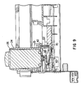
- the movable cap carriage 46 is caused to lift and rotate from the recessed position illustrated in Figs. 6 and 8 to the engaged position illustrated in Figs. 7 and 9. In the engaged position, cap 50 completely covers the nozzles of the ink jet head 32.
- the angle of incline of the guide slots 56 and 58 should be as steep as possible so as to raise the capping mechanism 44 in the shortest possible lateral distance.
- the first guide slot 56 receiving the pin 48 adjacent the cap 50 is made steeper such that the cap 50 is disposed below a top surface 64 of the maintenance device cover 54 in the recessed position (Figs. 6 and 8).
- the cap carriage 46 is shifted and rotated into the engaged position (Figs. 7 and 9), engaging the ink jet head 32 of the ink jet printing apparatus.
- the maintenance device 40 is fixed to the printing apparatus in a maintenance device frame 70.
- the wiper 42 is fixed to the frame 70 by any suitable securing means.
- the wiper 42 may be deflected slightly toward the maintenance area MA.
- the retaining wall 60 prevents the wiper 42 from deflecting beyond a predetermined position, thus preventing this permanent deflection.
- the retaining wall 60 is preferably formed of a rigid material such as plastic and therefore has greater rigidity than the wiper 42.
- the wiper 42 is deflected by the print head 32, there may be an instance where the wiper blade 42 is caught between the cap 50 and the ink jet head 32 (see, for example, Fig. 3 of US-A-5,202,702, discussed above).
- the retaining wall 60 prevents the wiper 42 from being deflected into the path of the capping mechanism 44. Therefore, even though the wiper 42 is disposed very near the capping mechanism 44 to minimize the maintenance area MA, an interference between the cap 50 and the wiper 42 is avoided.
- the printing carriage 24 and the print cartridge 26 are disposed such that an end portion of the print cartridge 26 extends outside of (below in Fig. 8) the printing carriage 24 forming a stepped area 68 adjacent the printing carriage 24.
- the wiper 42 in the engaged position, is disposed in the stepped area 68 such that there is a clearance between the wiper 42 and the printing carriage 24.
- the stepped area 68 enables the wiper blade 42 to fully recoil from any deflection caused during wiping of the ink jet head 32. As a result, the wiper 42 is prevented from becoming permanently deflected, thereby extending the life of the wiper 42.
- the stepped area 68 ensures that residual ink that is wiped from the ink jet head 32 is separated from the printing carriage 24 and print cartridge 26 into the maintenance device 40. Accordingly, the wiper 42 can be disposed below the carriage 24 without any problem when the carriage is in the maintenance area MA. This structure further minimizes the space for the maintenance device 40, while maximizing the amount of space available for printing.
- the deflected wiper 42 would give the print cartridge 26 great frictional resistance when the printing carriage 24 is shifted from the maintenance area MA to the printing area PA for printing. Further, residual ink that is wiped from the ink jet head 32 by the wiper 42 may dry on the printing carriage 24, causing the ink to be dropped on a paper during a subsequent printing operation. An ink buildup on the printing carriage 24 and/or the wiper 42 would significantly reduce the efficiency of the maintenance device.
- a spring 62 is disposed between the movable cap carriage 46 and a base portion of the wall 60.
- the spring 62 is a compression spring, urging the movable cap carriage 46 toward the recessed position.
- the spring 62 causes the movable cap carriage 46 to shift from the engaged position (Fig. 9) to the recessed position (Fig. 8).
- the spring 62 is fixed so as to be disposed at an angle between the angles of the second guide slot 58 and the first guide slot 56, and preferably substantially corresponding to the angle of the second guide slot 58.
- the cap 50 is telescopically slidable in an aperture 74 through the cap carriage 46.
- a spring 72 is disposed between the cap carriage 46 and the cap 50.
Landscapes
- Ink Jet (AREA)
Applications Claiming Priority (2)
| Application Number | Priority Date | Filing Date | Title |
|---|---|---|---|
| US368308 | 1982-04-14 | ||
| US08/368,308 US5627573A (en) | 1995-01-04 | 1995-01-04 | Maintenance device in an ink jet printing apparatus |
Publications (3)
| Publication Number | Publication Date |
|---|---|
| EP0720912A2 true EP0720912A2 (de) | 1996-07-10 |
| EP0720912A3 EP0720912A3 (de) | 1997-04-09 |
| EP0720912B1 EP0720912B1 (de) | 2000-04-19 |
Family
ID=23450703
Family Applications (1)
| Application Number | Title | Priority Date | Filing Date |
|---|---|---|---|
| EP95309524A Expired - Lifetime EP0720912B1 (de) | 1995-01-04 | 1995-12-29 | Pflegevorrichtung in einem Tintenstrahldrucker |
Country Status (3)
| Country | Link |
|---|---|
| US (1) | US5627573A (de) |
| EP (1) | EP0720912B1 (de) |
| DE (1) | DE69516384T2 (de) |
Cited By (6)
| Publication number | Priority date | Publication date | Assignee | Title |
|---|---|---|---|---|
| EP0832746A1 (de) * | 1996-09-23 | 1998-04-01 | Pitney Bowes Inc. | Tintenstrahldrucker mit vorrichtung zur justierung eines druckkopfes mit einem erwartungssystem |
| EP0850773A3 (de) * | 1996-11-22 | 1999-07-21 | Seiko Epson Corporation | Tintenstrahlaufzeichnunsgerät |
| EP0922583A3 (de) * | 1997-12-12 | 1999-07-21 | Lexmark International, Inc. | Wartungsstation für eine Tintenkassette eines Druckers |
| US6007180A (en) * | 1996-02-26 | 1999-12-28 | Brother Kogyo Kabushiki Kaisha | Ink-jet printer with printing head cap |
| EP1243424A2 (de) | 2001-03-21 | 2002-09-25 | Francotyp-Postalia AG & Co. KG | Vorrichtung zum Drucken |
| EP3192661A3 (de) * | 2016-01-13 | 2017-09-27 | OCE Holding B.V. | Aufschlagdämpfungsvorrichtung für druckkopfbaugruppe und druckvorrichtung damit |
Families Citing this family (23)
| Publication number | Priority date | Publication date | Assignee | Title |
|---|---|---|---|---|
| US6109726A (en) * | 1996-03-09 | 2000-08-29 | Lee; Yong-Duk | Service station of ink-jet printer |
| AU132828S (en) * | 1997-03-03 | 1998-02-09 | Hewlett Packard Co | Printhead service station unit |
| US5890823A (en) * | 1997-08-27 | 1999-04-06 | Sampo Corporation | Service station wiping mechanism in a printing unit |
| USD430600S (en) * | 1999-02-18 | 2000-09-05 | Hewlett-Packard Company | Printhead service station unit |
| US6648448B1 (en) | 2000-05-12 | 2003-11-18 | Lexmark International, Inc. | Waste ink management system for an ink jet printer |
| US6315386B1 (en) | 2000-05-24 | 2001-11-13 | Lexmark International, Inc. | Ink jet maintenance station having acoustic dampening |
| US6412905B1 (en) * | 2000-12-21 | 2002-07-02 | Acer Communications And Multimedia | Ink jet cap with vent |
| USD477358S1 (en) | 2002-02-08 | 2003-07-15 | Illinois Tool Works Inc. | Maintenance module for fluid jetting head |
| USD473896S1 (en) | 2002-08-12 | 2003-04-29 | Yi-Tsung Yan | Refilling clip for inkjet cartridge |
| USD473895S1 (en) | 2002-08-12 | 2003-04-29 | Yi-Tsung Yan | Refilling clip for inkjet cartridge |
| US6773088B2 (en) * | 2002-11-15 | 2004-08-10 | Lexmark International, Inc. | Double lipped printhead maintenance cap |
| US6869164B2 (en) * | 2003-05-29 | 2005-03-22 | Lexmark International, Inc. | Maintenance station having acoustical dampening for use in an imaging apparatus |
| JP4174404B2 (ja) * | 2003-10-01 | 2008-10-29 | キヤノン株式会社 | 撮像装置、画像表示方法、プログラムおよび記憶媒体 |
| MXPA06007851A (es) * | 2004-01-15 | 2007-01-31 | Warner Chilcott Co Inc | Profarmacos di-esteroidales de etinil estradiol. |
| US7246875B2 (en) * | 2004-12-06 | 2007-07-24 | Silverbrook Research Pty Ltd | Protector for a printhead capping facility |
| US7322669B2 (en) * | 2004-12-06 | 2008-01-29 | Silverbrook Research Pty Ltd | Inkjet printer with protector for a printhead capping facility |
| US7341328B2 (en) | 2004-12-06 | 2008-03-11 | Silverbrook Research Pty Ltd | Inkjet printer with two-stage capping mechanism |
| US7284820B2 (en) * | 2004-12-06 | 2007-10-23 | Silverbrook Research Pty Ltd | Two-stage capping mechanism for inkjet printers |
| EP1827839B1 (de) * | 2004-12-06 | 2009-02-18 | Silverbrook Research Pty. Ltd | Zweistufiger abdeckmechanismus für tintenstrahldrucker |
| USD540853S1 (en) * | 2005-02-14 | 2007-04-17 | Hewlett-Packard Development Company, L.P. | Printhead service unit |
| USD611092S1 (en) * | 2007-03-12 | 2010-03-02 | Mimaki Engineering Co., Ltd. | Defoaming plate for maintenance of ink jet head |
| USD583408S1 (en) * | 2007-05-24 | 2008-12-23 | Tri-Century Corporation | Printer cartridge holder |
| CN103552378B (zh) * | 2013-11-05 | 2016-08-17 | 郑州新世纪数码打印科技有限公司 | 模块化的双喷头墨栈 |
Family Cites Families (9)
| Publication number | Priority date | Publication date | Assignee | Title |
|---|---|---|---|---|
| US4533927A (en) * | 1982-05-06 | 1985-08-06 | Sharp Kabushiki Kaisha | Capping mechanism for preventing nozzle blocking in an ink jet system printer |
| JPS61118255A (ja) * | 1984-11-14 | 1986-06-05 | Canon Inc | インクジエツトプリンタの吸引回復装置 |
| US5202702A (en) * | 1985-04-08 | 1993-04-13 | Canon Kabushiki Kaisha | Ink jet recording apparatus and a method of cleaning a recording head used in the apparatus |
| US5266974A (en) * | 1989-05-18 | 1993-11-30 | Canon Kabushiki Kaisha | Ink jet recording apparatus including means for controlling speed of wiper member |
| JP2821809B2 (ja) * | 1990-10-01 | 1998-11-05 | キヤノン株式会社 | インクジェット記録装置 |
| US5260724A (en) * | 1991-01-09 | 1993-11-09 | Seiko Epson Corporation | Capping device for ink jet printer |
| US5517219A (en) * | 1992-01-16 | 1996-05-14 | Canon Kabushiki Kaisha | Ink jet recording apparatus having an improved capping mechanism |
| US5621441A (en) * | 1992-09-21 | 1997-04-15 | Hewlett-Packard Company | Service station for inkjet printer having reduced noise, increased ease of assembly and variable wiping capability |
| US5440331A (en) * | 1992-12-21 | 1995-08-08 | Hewlett-Packard Company | Printhead servicing apparatus |
-
1995
- 1995-01-04 US US08/368,308 patent/US5627573A/en not_active Expired - Lifetime
- 1995-12-29 DE DE69516384T patent/DE69516384T2/de not_active Expired - Lifetime
- 1995-12-29 EP EP95309524A patent/EP0720912B1/de not_active Expired - Lifetime
Cited By (14)
| Publication number | Priority date | Publication date | Assignee | Title |
|---|---|---|---|---|
| US6007180A (en) * | 1996-02-26 | 1999-12-28 | Brother Kogyo Kabushiki Kaisha | Ink-jet printer with printing head cap |
| US6241336B1 (en) | 1996-02-26 | 2001-06-05 | Brother Kogyo Kabushiki Kaisha | Ink-jet printer with printing head cap |
| EP0832746A1 (de) * | 1996-09-23 | 1998-04-01 | Pitney Bowes Inc. | Tintenstrahldrucker mit vorrichtung zur justierung eines druckkopfes mit einem erwartungssystem |
| US6286931B1 (en) | 1996-11-22 | 2001-09-11 | Seiko Epson Corporation | Ink jet recording apparatus |
| EP0850773A3 (de) * | 1996-11-22 | 1999-07-21 | Seiko Epson Corporation | Tintenstrahlaufzeichnunsgerät |
| EP1167042A1 (de) * | 1996-11-22 | 2002-01-02 | Seiko Epson Corporation | Tintenstrahlaufzeichnungsgerät |
| EP1167041A1 (de) * | 1996-11-22 | 2002-01-02 | Seiko Epson Corporation | Tintenstrahlaufzeichnungsgerät |
| US6168257B1 (en) | 1997-12-12 | 2001-01-02 | Lexmark International, Inc. | Maintenance station for an ink cartridge for a printer |
| EP0922583A3 (de) * | 1997-12-12 | 1999-07-21 | Lexmark International, Inc. | Wartungsstation für eine Tintenkassette eines Druckers |
| US6422679B1 (en) | 1997-12-12 | 2002-07-23 | Lexmark International, Inc | Maintenance station for an ink cartridge for a printer |
| EP1243424A2 (de) | 2001-03-21 | 2002-09-25 | Francotyp-Postalia AG & Co. KG | Vorrichtung zum Drucken |
| US6709087B2 (en) | 2001-03-21 | 2004-03-23 | Francotyp Postalia Ag & Co. | Printing device |
| EP3192661A3 (de) * | 2016-01-13 | 2017-09-27 | OCE Holding B.V. | Aufschlagdämpfungsvorrichtung für druckkopfbaugruppe und druckvorrichtung damit |
| US9802431B2 (en) | 2016-01-13 | 2017-10-31 | Océ Holding B.V. | Impact damping device for print-head assembly and printing apparatus incorporating same |
Also Published As
| Publication number | Publication date |
|---|---|
| EP0720912A3 (de) | 1997-04-09 |
| DE69516384T2 (de) | 2000-09-21 |
| US5627573A (en) | 1997-05-06 |
| EP0720912B1 (de) | 2000-04-19 |
| DE69516384D1 (de) | 2000-05-25 |
Similar Documents
| Publication | Publication Date | Title |
|---|---|---|
| US5627573A (en) | Maintenance device in an ink jet printing apparatus | |
| US5627574A (en) | Maintenance device in an ink jet printing apparatus | |
| US5997128A (en) | Translational service station for imaging inkjet printheads | |
| JP3710013B2 (ja) | カラー可能単一カートリッジ・インクジェット・サービスステーション | |
| US6164767A (en) | Ink jet recording apparatus having a driving wheel mechanism for pressurizing tubes of a tube pump | |
| EP1754607A2 (de) | Tintenstrahlbilderzeugungsgerät und Verfahren zur Wartung dessen Düsenanordnung | |
| US20010017635A1 (en) | Image forming apparatus | |
| US20020060711A1 (en) | Ink jet printer provided with maintenance system | |
| US7175253B2 (en) | Maintenance apparatus used with an inkjet printer | |
| EP1040924B1 (de) | Tintenstrahlaufzeichnungsgerät | |
| US6286931B1 (en) | Ink jet recording apparatus | |
| US6371595B1 (en) | Ink jet printer | |
| US7922280B2 (en) | Maintenance station for an imaging apparatus | |
| JP5446827B2 (ja) | 画像形成装置 | |
| US6755504B2 (en) | Independent wiping of printhead | |
| US6869164B2 (en) | Maintenance station having acoustical dampening for use in an imaging apparatus | |
| US6896353B2 (en) | Inkjet printhead squeegee | |
| EP4516514A1 (de) | Flüssigkeitsausstossvorrichtung | |
| GB2315816A (en) | Tube pump for ink jet recording apparatus | |
| KR100234436B1 (ko) | 잉크젯 프린터의 홈포지션 구조변경장치 | |
| JP3363677B2 (ja) | インクジェット記録装置 | |
| JP3573207B2 (ja) | インクジェット式記録装置 | |
| JP2007007920A (ja) | インクジェット記録装置 | |
| JPH09262976A (ja) | インクジェット記録装置 |
Legal Events
| Date | Code | Title | Description |
|---|---|---|---|
| PUAI | Public reference made under article 153(3) epc to a published international application that has entered the european phase |
Free format text: ORIGINAL CODE: 0009012 |
|
| AK | Designated contracting states |
Kind code of ref document: A2 Designated state(s): DE FR GB |
|
| PUAL | Search report despatched |
Free format text: ORIGINAL CODE: 0009013 |
|
| AK | Designated contracting states |
Kind code of ref document: A3 Designated state(s): DE FR GB |
|
| 17P | Request for examination filed |
Effective date: 19970925 |
|
| 17Q | First examination report despatched |
Effective date: 19981103 |
|
| GRAG | Despatch of communication of intention to grant |
Free format text: ORIGINAL CODE: EPIDOS AGRA |
|
| GRAG | Despatch of communication of intention to grant |
Free format text: ORIGINAL CODE: EPIDOS AGRA |
|
| GRAG | Despatch of communication of intention to grant |
Free format text: ORIGINAL CODE: EPIDOS AGRA |
|
| GRAH | Despatch of communication of intention to grant a patent |
Free format text: ORIGINAL CODE: EPIDOS IGRA |
|
| GRAH | Despatch of communication of intention to grant a patent |
Free format text: ORIGINAL CODE: EPIDOS IGRA |
|
| GRAA | (expected) grant |
Free format text: ORIGINAL CODE: 0009210 |
|
| AK | Designated contracting states |
Kind code of ref document: B1 Designated state(s): DE FR GB |
|
| REF | Corresponds to: |
Ref document number: 69516384 Country of ref document: DE Date of ref document: 20000525 |
|
| ET | Fr: translation filed | ||
| PLBE | No opposition filed within time limit |
Free format text: ORIGINAL CODE: 0009261 |
|
| STAA | Information on the status of an ep patent application or granted ep patent |
Free format text: STATUS: NO OPPOSITION FILED WITHIN TIME LIMIT |
|
| 26N | No opposition filed | ||
| REG | Reference to a national code |
Ref country code: GB Ref legal event code: IF02 |
|
| PGFP | Annual fee paid to national office [announced via postgrant information from national office to epo] |
Ref country code: GB Payment date: 20141124 Year of fee payment: 20 |
|
| PGFP | Annual fee paid to national office [announced via postgrant information from national office to epo] |
Ref country code: FR Payment date: 20141124 Year of fee payment: 20 |
|
| PGFP | Annual fee paid to national office [announced via postgrant information from national office to epo] |
Ref country code: DE Payment date: 20141222 Year of fee payment: 20 |
|
| REG | Reference to a national code |
Ref country code: DE Ref legal event code: R071 Ref document number: 69516384 Country of ref document: DE |
|
| REG | Reference to a national code |
Ref country code: GB Ref legal event code: PE20 Expiry date: 20151228 |
|
| PG25 | Lapsed in a contracting state [announced via postgrant information from national office to epo] |
Ref country code: GB Free format text: LAPSE BECAUSE OF EXPIRATION OF PROTECTION Effective date: 20151228 |