EP0721029A1 - Bodenverdichtungsgerät - Google Patents
Bodenverdichtungsgerät Download PDFInfo
- Publication number
- EP0721029A1 EP0721029A1 EP96650001A EP96650001A EP0721029A1 EP 0721029 A1 EP0721029 A1 EP 0721029A1 EP 96650001 A EP96650001 A EP 96650001A EP 96650001 A EP96650001 A EP 96650001A EP 0721029 A1 EP0721029 A1 EP 0721029A1
- Authority
- EP
- European Patent Office
- Prior art keywords
- compactor
- machine
- compacting
- ground
- chassis
- Prior art date
- Legal status (The legal status is an assumption and is not a legal conclusion. Google has not performed a legal analysis and makes no representation as to the accuracy of the status listed.)
- Withdrawn
Links
- 230000000712 assembly Effects 0.000 claims abstract description 14
- 238000000429 assembly Methods 0.000 claims abstract description 14
- 238000000034 method Methods 0.000 claims description 10
- 238000012544 monitoring process Methods 0.000 claims description 10
- 239000012530 fluid Substances 0.000 claims description 7
- 238000005056 compaction Methods 0.000 abstract description 30
- 238000006243 chemical reaction Methods 0.000 abstract description 7
- 238000007373 indentation Methods 0.000 abstract description 7
- 230000035515 penetration Effects 0.000 abstract description 6
- 239000002689 soil Substances 0.000 description 11
- 238000006073 displacement reaction Methods 0.000 description 7
- 238000005470 impregnation Methods 0.000 description 4
- 239000004575 stone Substances 0.000 description 4
- 238000010276 construction Methods 0.000 description 3
- XLYOFNOQVPJJNP-UHFFFAOYSA-N water Substances O XLYOFNOQVPJJNP-UHFFFAOYSA-N 0.000 description 3
- 238000002360 preparation method Methods 0.000 description 2
- 230000005540 biological transmission Effects 0.000 description 1
- 230000000694 effects Effects 0.000 description 1
- 239000000203 mixture Substances 0.000 description 1
- 238000005096 rolling process Methods 0.000 description 1
- 238000003892 spreading Methods 0.000 description 1
- 239000000725 suspension Substances 0.000 description 1
Images



Classifications
-
- E—FIXED CONSTRUCTIONS
- E01—CONSTRUCTION OF ROADS, RAILWAYS, OR BRIDGES
- E01C—CONSTRUCTION OF, OR SURFACES FOR, ROADS, SPORTS GROUNDS, OR THE LIKE; MACHINES OR AUXILIARY TOOLS FOR CONSTRUCTION OR REPAIR
- E01C19/00—Machines, tools or auxiliary devices for preparing or distributing paving materials, for working the placed materials, or for forming, consolidating, or finishing the paving
- E01C19/22—Machines, tools or auxiliary devices for preparing or distributing paving materials, for working the placed materials, or for forming, consolidating, or finishing the paving for consolidating or finishing laid-down unset materials
- E01C19/23—Rollers therefor; Such rollers usable also for compacting soil
- E01C19/28—Vibrated rollers or rollers subjected to impacts, e.g. hammering blows
- E01C19/288—Vibrated rollers or rollers subjected to impacts, e.g. hammering blows adapted for monitoring characteristics of the material being compacted, e.g. indicating resonant frequency, measuring degree of compaction, by measuring values, detectable on the roller; using detected values to control operation of the roller, e.g. automatic adjustment of vibration responsive to such measurements
-
- E—FIXED CONSTRUCTIONS
- E02—HYDRAULIC ENGINEERING; FOUNDATIONS; SOIL SHIFTING
- E02D—FOUNDATIONS; EXCAVATIONS; EMBANKMENTS; UNDERGROUND OR UNDERWATER STRUCTURES
- E02D3/00—Improving or preserving soil or rock, e.g. preserving permafrost soil
- E02D3/02—Improving by compacting
- E02D3/026—Improving by compacting by rolling with rollers usable only for or specially adapted for soil compaction, e.g. sheepsfoot rollers
Definitions
- the invention relates to a ground compacting machine of the type comprising a chassis, a ballast supported on the chassis, and a compactor assembly having at least one compactor mounted on the chassis by a compactor drive to transmit the weight of the ballast to the compactor assembly.
- a ground compacting machine of the type comprising a chassis, a ballast supported on the chassis, and a compactor assembly having at least one compactor mounted on the chassis by a compactor drive to transmit the weight of the ballast to the compactor assembly.
- the invention is characterised in that the compactor drive comprises a control means for monitoring the compacting force of the compactor assembly to indicate ground resistance.
- the weight of the ballast may be distributed between the assemblies for individual compaction in small areas, each area associated with a single assembly.
- the compactor drive comprises a fluid drive and the control means comprises means for sensing fluid pressure.
- the fluid drive may be an hydraulic drive and the control means comprises an hydraulic pressure indicator. Hydraulic drives are widely used on compacting machines and are a particularly effective and inexpensive way of providing the drive and pressure sensing.
- each compactor comprises a rotatable hub carrying a plurality of compacting feet. This is a very simple way of allowing compaction of individual areas, leaving other areas uncompacted. This helps to avoid soil displacement and allows effective impregnation of fine infill to the ground to dry it.
- the feet may be disc-shaped for very effective ground penetration.
- the foot is mounted on a radially arranged arm so that the leading edge of the foot is further away from the hub than the trailing edge. This also helps ground penetration and also allows deep penetration - limited only by the length of the arms.
- the compactor assembly may include a vibrator means to improve effectiveness.
- the invention provides a ground compacting machine comprising a chassis, a ballast supported on the chassis and a compactor assembly having at least one compactor mounted on the chassis by a compactor drive to transmit the weight of the ballast to the compactor assembly, characterised in that:-
- This combination of features provide for effective compaction of all areas and deep penetration at separate discrete locations to avoid soil displacement.
- the invention provides a method of compacting the ground, the method comprising the steps of:-
- the invention provides a method of compacting the ground over a base area using a compacting machine, the method comprising:
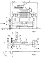
- the machine 1 is self-propelled and comprises a mobile frame or chassis 2, a drive cab 3 and wheels 4.
- the chassis 2 supports a ballast 10 which in this embodiment has a weight of 25 tonnes.
- the ballast 10 is slidable back and forth on the chassis 2 between various longitudinal positions as indicated by the arrow A and the interrupted lines by a pair of hydraulic rams 11, one on each side of the chassis 2.
- the machine 1 also comprises a set of five rear compactor assemblies 19, each having two compactors 20 mounted at the rear of the machine. There is also a side assembly comprising a single compactor 21 mounted transversely of the machine. Further, an aggregate spreading blade 22 is mounted forwardly of the machine.
- An hydraulic control panel 23 is mounted in the cab 3 to allow driver control of the various compactor assemblies.
- the hydraulic circuits connecting the hydraulic power plant (not shown), the control panel 23 and the compactors 20 and 21 have pressure release valves which can be selectively introduced.
- the release valves set the maximum pressure for transmission of the ballast weight to the compactors, and the sensors allow the driver to monitor the pressure required. This indicates the ground resistance at the associated compactor(s).
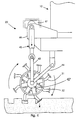
- the compactor 21 comprises a hub 30 from which eight arms 31 extend.
- a compacting foot 32 (“sheepsfoot”) is mounted at the end of each arm 31.
- Each foot is disc-shaped having a diameter of 75 mm.
- the arms 31 are cranked so that the leading edge of the feet as they rotate in the direction of travel of the machine 1 is at a slightly lower level. This provides for compaction in a simpler manner.
- the hub 30 is rotatably supported by an axle 33 which is pivotally connected to a support plate 34 which has pivot holes 35, by a pivot pin 36 in one of the holes 35.
- the hub is connected by bearings to a non-rotating sleeve 37 which extends around the axle 33 and is connected to it at one of a number of transverse adjustment holes 38 to provide different transverse settings as indicated by the arrow B.
- the sleeve 37 is pivotally connected to a compacting drive, namely, a vertically arranged hydraulic ram 39 connected to an anchorage 40, shown in Fig. 1.
- the different pivot holes 35 allow different pivot axes to provide different responses to movement of the ram 39 - providing different angles of inclination of the compactor 21.
- the anchorage 40 is a laterally extending cantilevered arm rigidly connected to the chassis.
- a hub 42 for a pair of compactors 20 is connected to a support arm 43 which is in turn pivotally connected to a vertically arranged hydraulic ram 45.
- the hub 42 is also connected by a suspension strut 44 to the chassis.
- the ram 45 is connected at its upper end to a bracket 46 on the chassis 2.
- a vibrator 47 having an eccentric shaft driven by the machine's hydraulic circuits is connected to the bracket 46.
- the machine 1 is driven over the ground 30 with the compactors 20 in their operative positions.
- the hydraulic pressure in the hydraulic circuits indicates the ground resistance at the location of each compactor assembly. This allows the drive to immediately identify soft areas for additional compaction.
- the hubs 42 rotate whereby each foot 32 in turn penetrates the ground to provide a set of separate, discrete indentations 51 in the ground. Because the machine 1 is being driven, the feet 33 have a relatively clean exit from the indentations and do not tend to lift soil as they are exiting from the indentations. It will thus be appreciated that the compactors 20 compact locally at discrete locations to provide discrete indentations in the ground.
- the machine 1 effectively provides five different compactors, each of which operates over a very small surface area. Accordingly, where small pockets of the ground are particularly soft, they are individually compacted to the correct level.
- the maximum level of compaction is set by the hydraulic pressure in the rams 45 and this pressure urges the compactors 20 downwardly against the reaction force of the ground.
- the rams 39 and 45 distribute the available downward force provided by the ballast 10 to six different assemblies of compactors at the required level for each compactor.
- the pair of compactors 20 at one side of the machine 1 may be required to press down against a reaction force of 20 bar, whereas the compactors on the other side may be required to counter a reaction force of 10 bar.
- the driver in the cab 3 is provided with feedback as to the reaction force or resistance provided at each of the pairs of compactors 20.
- the control panel 23 includes a set of dials, each of which indicates the hydraulic pressure in each of the hydraulic circuits and this provides a measure of the ground resistance or reaction force. In this way, the ground may be compacted in a much more controlled manner in which the operator knows which areas require more compaction and the relevant information can be provided to the engineers on-site. It is envisaged that the data may be recorded electronically or on a hard copy for later analysis.
- the next step of compaction is to apply a layer 55 of a fine, dry aggregate over the ground after it has been compacted in one pass.
- the aggregate 55 may be of the type known as "804" but may be of any type which is dry so that it helps in reducing the overall moisture content of the ground and is fine so that there are no voids created in the ground.
- the next stage is a second pass of compaction using the machine 1. It is not necessary that the feet of the compactors are in registry with the original position and the overall effect is that the aggregate 55 is impregnated into the ground. Impregnation of the aggregate 55 is particularly effective because it is deposited into relatively deep indentations 51 in the ground so that there is access to a low level in the ground.
- FIG. 7 an arrangement is shown whereby alternative pairs of compactors 20 are operated in one pass according to the ground conditions for the pass. It will be appreciated that any desired configuration of compactors 20 may be operated. This provides a large degree of versatility in operation of the machine.
- the side compactor 21 may be operated in much the same way as the rear compactors 20, with the rear compactors 20 in an upper inoperative position. This may provide for additional compaction for road preparation, or it may alternatively be used for verge compaction at a roadside verge.
- the ballast 10 is slid forwardly, as indicated by the arrow A in Fig. 1, to a forward position at which it provides more effective ballast for the ram 39 of the side compactor 31.
- the machine 1 provides for efficient road widening by compacting the roadside verge in a simple manner to provide a very strong foundation, upon which relatively little stone is required before application of the surface dressing.
- the machine 1 may include a side compactor only without any rear compactors and may therefore be regarded as a dedicated roadside verge compactor. Equally, there may be no side compactor and rear compactors only. However, where the machine 1 does include both rear and side compactors as shown in the drawings, the side compactor may be used for general ground compaction for road preparation.
- the invention uses very simple mechanical features to provide compaction over very small areas according to the required compaction force. This ensures that the ground is uniformly prepared before further work is carried out. It will also be appreciated that the invention provides for feedback of a good deal of information regarding the ground conditions to the driver so that the appropriate decisions can be made. Another very important feature of the invention is the fact that the machine compacts ground having a high moisture content in a very effective manner by helping to remove water and allowing for very effective impregnation of a fine and dry aggregate to reduce the overall moisture content.
- the invention is not limited to the embodiments hereinbefore described.
- the feet instead of the feet being mounted on arms about a hub, they could be mounted at the end of a reciprocating rod which is driven in a reciprocating manner by a drive ram or other drive means.
- a pneumatic drive or alternatively a mechanical spring arrangement could be used to apply a downward force from the ballast to the feet.
- the machine need not necessarily have compactors with feet.
- rollers could be used, possibly with protruding rims or ridges.
Landscapes
- Engineering & Computer Science (AREA)
- Structural Engineering (AREA)
- Life Sciences & Earth Sciences (AREA)
- Civil Engineering (AREA)
- Environmental & Geological Engineering (AREA)
- Agronomy & Crop Science (AREA)
- Architecture (AREA)
- Soil Sciences (AREA)
- General Life Sciences & Earth Sciences (AREA)
- Mining & Mineral Resources (AREA)
- Paleontology (AREA)
- General Engineering & Computer Science (AREA)
- Investigation Of Foundation Soil And Reinforcement Of Foundation Soil By Compacting Or Drainage (AREA)
Applications Claiming Priority (2)
| Application Number | Priority Date | Filing Date | Title |
|---|---|---|---|
| IE950008 | 1995-01-06 | ||
| IE950008 | 1995-01-06 |
Publications (1)
| Publication Number | Publication Date |
|---|---|
| EP0721029A1 true EP0721029A1 (de) | 1996-07-10 |
Family
ID=11040617
Family Applications (1)
| Application Number | Title | Priority Date | Filing Date |
|---|---|---|---|
| EP96650001A Withdrawn EP0721029A1 (de) | 1995-01-06 | 1996-01-08 | Bodenverdichtungsgerät |
Country Status (1)
| Country | Link |
|---|---|
| EP (1) | EP0721029A1 (de) |
Cited By (2)
| Publication number | Priority date | Publication date | Assignee | Title |
|---|---|---|---|---|
| RU2225909C1 (ru) * | 2002-10-29 | 2004-03-20 | Деникин Эрнст Иванович | Дорожный каток с вакуумной камерой |
| CN117758566A (zh) * | 2023-12-21 | 2024-03-26 | 潍柴动力股份有限公司 | 压路机的控制方法、装置、可读存储介质和电子设备 |
Citations (5)
| Publication number | Priority date | Publication date | Assignee | Title |
|---|---|---|---|---|
| US3067658A (en) * | 1960-02-19 | 1962-12-11 | Hyster Co | Earth compaction roll |
| US3146686A (en) * | 1962-07-23 | 1964-09-01 | William E Grace | Shoulder roller attachment for road rollers |
| GB1146339A (en) * | 1967-02-21 | 1969-03-26 | Baldwin Lima Hamilton Corp | Earth compacting device |
| US3797954A (en) * | 1972-05-23 | 1974-03-19 | Tampo Mfg Co | Ground compacting apparatus |
| EP0459062A1 (de) * | 1990-05-28 | 1991-12-04 | Caterpillar Paving Products Inc. | Einrichtung und Verfahren zur Überwachung einer Schwingungsvorrichtung |
-
1996
- 1996-01-08 EP EP96650001A patent/EP0721029A1/de not_active Withdrawn
Patent Citations (5)
| Publication number | Priority date | Publication date | Assignee | Title |
|---|---|---|---|---|
| US3067658A (en) * | 1960-02-19 | 1962-12-11 | Hyster Co | Earth compaction roll |
| US3146686A (en) * | 1962-07-23 | 1964-09-01 | William E Grace | Shoulder roller attachment for road rollers |
| GB1146339A (en) * | 1967-02-21 | 1969-03-26 | Baldwin Lima Hamilton Corp | Earth compacting device |
| US3797954A (en) * | 1972-05-23 | 1974-03-19 | Tampo Mfg Co | Ground compacting apparatus |
| EP0459062A1 (de) * | 1990-05-28 | 1991-12-04 | Caterpillar Paving Products Inc. | Einrichtung und Verfahren zur Überwachung einer Schwingungsvorrichtung |
Non-Patent Citations (1)
| Title |
|---|
| HIROAKI FUJII: "problems between soil and construction machinery with special reference to field compaction", JOURNAL OF TERRAMECHANICS, vol. 29, no. 1, OXFORD,GB, pages 35 - 55, XP000278239 * |
Cited By (2)
| Publication number | Priority date | Publication date | Assignee | Title |
|---|---|---|---|---|
| RU2225909C1 (ru) * | 2002-10-29 | 2004-03-20 | Деникин Эрнст Иванович | Дорожный каток с вакуумной камерой |
| CN117758566A (zh) * | 2023-12-21 | 2024-03-26 | 潍柴动力股份有限公司 | 压路机的控制方法、装置、可读存储介质和电子设备 |
Similar Documents
| Publication | Publication Date | Title |
|---|---|---|
| US4157877A (en) | Apparatus for compacting subgrade and pavement materials | |
| US20070239338A1 (en) | Worksite preparation method using compaction response and mapping information | |
| US6382873B1 (en) | Soil levelling device | |
| US6322287B1 (en) | Aggregate grading machine | |
| US7500803B2 (en) | Ground working device for liquid treated roads | |
| US3221619A (en) | Rotating roller machine | |
| US4964754A (en) | Concrete screeding machine | |
| DE1949845A1 (de) | Strassenaufreissmaschine | |
| US9121144B2 (en) | Method for compacting soil, applications of this method and devices for its implementation | |
| US6793437B2 (en) | Side-mounted shoulder compaction roller | |
| IES67368B2 (en) | A ground compacting machine | |
| US20210180271A1 (en) | Material density measurement for paver application | |
| US4911248A (en) | Earth compacting apparatus and method | |
| AU2003280334A1 (en) | Drop mass compaction of soil | |
| US20020141822A1 (en) | Apparatus and method for cold paving | |
| DE1808284A1 (de) | Fahrbare Gleisbearbeitungsmaschine,insbesondere Gleisrichtmaschine | |
| CN205134152U (zh) | 浇注式沥青混凝土专用摊铺机 | |
| FI92944C (fi) | Tienrakennusmassan levityslaite | |
| EP1533422A1 (de) | Vorrichtung zum Sanieren, Nivellieren und Verdichten von nicht asphaltierten Strassen | |
| JPH0520087Y2 (de) | ||
| DE3615996C2 (de) | Vorrichtung zum Einebnen und Verdichten von Schüttgütern | |
| CA1233811A (en) | Apparatus for enabling regulatable alteration of the friction grip between the wheels of a car and a substructure such as a road | |
| JPH0530561Y2 (de) | ||
| GB2616403A (en) | Agricultural roller apparatus | |
| JPH0131634Y2 (de) |
Legal Events
| Date | Code | Title | Description |
|---|---|---|---|
| PUAI | Public reference made under article 153(3) epc to a published international application that has entered the european phase |
Free format text: ORIGINAL CODE: 0009012 |
|
| AK | Designated contracting states |
Kind code of ref document: A1 Designated state(s): AT BE CH DE DK ES FR GB GR IE IT LI LU MC NL PT SE |
|
| 17P | Request for examination filed |
Effective date: 19961220 |
|
| 17Q | First examination report despatched |
Effective date: 19970730 |
|
| STAA | Information on the status of an ep patent application or granted ep patent |
Free format text: STATUS: THE APPLICATION IS DEEMED TO BE WITHDRAWN |
|
| 18D | Application deemed to be withdrawn |
Effective date: 19980210 |