EP0721032A2 - Rondelle de fixation - Google Patents
Rondelle de fixation Download PDFInfo
- Publication number
- EP0721032A2 EP0721032A2 EP95309336A EP95309336A EP0721032A2 EP 0721032 A2 EP0721032 A2 EP 0721032A2 EP 95309336 A EP95309336 A EP 95309336A EP 95309336 A EP95309336 A EP 95309336A EP 0721032 A2 EP0721032 A2 EP 0721032A2
- Authority
- EP
- European Patent Office
- Prior art keywords
- attachment plate
- section
- fingers
- washer
- insulation panel
- Prior art date
- Legal status (The legal status is an assumption and is not a legal conclusion. Google has not performed a legal analysis and makes no representation as to the accuracy of the status listed.)
- Granted
Links
Images


Classifications
-
- E—FIXED CONSTRUCTIONS
- E04—BUILDING
- E04B—GENERAL BUILDING CONSTRUCTIONS; WALLS, e.g. PARTITIONS; ROOFS; FLOORS; CEILINGS; INSULATION OR OTHER PROTECTION OF BUILDINGS
- E04B1/00—Constructions in general; Structures which are not restricted either to walls, e.g. partitions, or floors or ceilings or roofs
- E04B1/62—Insulation or other protection; Elements or use of specified material therefor
- E04B1/74—Heat, sound or noise insulation, absorption, or reflection; Other building methods affording favourable thermal or acoustical conditions, e.g. accumulating of heat within walls
- E04B1/76—Heat, sound or noise insulation, absorption, or reflection; Other building methods affording favourable thermal or acoustical conditions, e.g. accumulating of heat within walls specifically with respect to heat only
- E04B1/762—Exterior insulation of exterior walls
- E04B1/7629—Details of the mechanical connection of the insulation to the wall
- E04B1/7633—Dowels with enlarged insulation retaining head
-
- B—PERFORMING OPERATIONS; TRANSPORTING
- B25—HAND TOOLS; PORTABLE POWER-DRIVEN TOOLS; MANIPULATORS
- B25C—HAND-HELD NAILING OR STAPLING TOOLS; MANUALLY OPERATED PORTABLE STAPLING TOOLS
- B25C1/00—Hand-held nailing tools; Nail feeding devices
- B25C1/08—Hand-held nailing tools; Nail feeding devices operated by combustion pressure
- B25C1/10—Hand-held nailing tools; Nail feeding devices operated by combustion pressure generated by detonation of a cartridge
- B25C1/18—Details and accessories, e.g. splinter guards, spall minimisers
- B25C1/188—Arrangements at the forward end of the barrel, e.g. splinter guards, spall minimisers, safety arrangements, silencers, bolt retainers
-
- E—FIXED CONSTRUCTIONS
- E04—BUILDING
- E04D—ROOF COVERINGS; SKY-LIGHTS; GUTTERS; ROOF-WORKING TOOLS
- E04D3/00—Roof covering by making use of flat or curved slabs or stiff sheets
- E04D3/36—Connecting; Fastening
- E04D3/3601—Connecting; Fastening of roof covering supported by the roof structure with interposition of a insulating layer
- E04D3/3603—Connecting; Fastening of roof covering supported by the roof structure with interposition of a insulating layer the fastening means being screws or nails
Definitions
- This invention pertains to building construction, and more particularly to apparatus for attaching insulation panels to structural substrates.
- the insulation panels are typically attached in place by mechanical fasteners such as screws or nails in conjunction with specialized attachment devices.
- the attachment devices are commonly thin plates having relatively large areas. The plates are placed on the insulation panel surface opposite the substrate, and the fasteners are driven through the plates and insulation panel into the substrate.
- U.S. patents 5,054,983 and 5,171,118 show insulation panel attachment devices that pass entirely through insulation panels. Those attachment devices can thus clamp insulation panels to a substrate with a uniform force.
- the devices of the two foregoing patents suffer the handicap of being unable to accommodate insulation panels having thicknesses that vary from a nominal thickness.
- the devices of the foregoing patents require installation by power setting tools that have individual feeding of the nails and the powder loads. Consequently, installation times are undesirably high.
- an attachment plate for attaching an insulation panel to a substrate comprises:
- an attachment plate for insulation panels is provided that greatly increases the productivity of attaching insulation panels to buildings. This is accomplished by designing the attachment plate both to be installed using a combustion powered repeating type setting tool and to accommodate insulation panels of varying thickness.
- the attachment plate can accommodate insulation panels having thicknesses different than a nominal thickness. If the insulation panel thickness is slightly less than nominal, the attachment plate second end contacts the substrate before the washer is flush with the panel exposed surface. Upon firing the tool, the nail forces the attachment plate fully into the panel by bending the tabs the amount necessary to assure that the installed attachment plate does not protrude above the panel exposed surface. If the panel has a slightly greater thickness than nominal, the attachment plate second end is spaced from the substrate when the attachment plate washer is flush with the panel exposed surface. When the tool is fired, the nail forces the washer to penetrate the panel a slightly further amount until the attachment plate second end contacts the substrate. In that situation, the tabs do not bend.
- the apparatus of the invention using a multi-section attachment plate, thus enables insulation panels to be very rapidly and easily installed on a building using a repeating impulse tool.
- the attachment plate also enables insulation panels of varying thicknesses to be installed with consistent clamping force.
- an attachment plate 1 for insulation panels is illustrated that includes the present invention.
- the attachment plate 1 is constructed as a tubular piece that is symmetrical about a longitudinal axis 3 and that has first and second ends 2 and 5, respectively.
- a washer 7 of relatively large outer diameter 8 is at the plate first end 2 and having a central opening 10.
- a number of openings pass through the washer 7.
- the openings may be in the form of holes 9 having frusto-conical cross sections, with the holes having their apexes toward the attachment plate first end 2.
- the holes 9 provide flexibility to the washer.
- a tubular member 11 Joined to the washer 7 and extending toward the attachment plate second end 5 is a tubular member 11.
- the tubular member 11 has four sections 13, 15, 17, and 19.
- the first section 13 has an outer diameter 21 that is substantially smaller than the washer outer diameter 8.
- the first section has an inner diameter 23 that is the same size as the diameter of the washer central opening 10.
- the inner diameter 23 terminates in a first annular transverse surface 24.
- the second section 15 of the tubular member 11 has an outer diameter 25 that preferably is less than the outer diameter 21 of the first section 13 and an inner diameter 27 that is less than the first section inner diameter 23.
- the second section inner diameter 27 blends into the transverse surface 24 of the first section 13 through a dished transition surface 28.
- the second section inner diameter terminates in a second transverse surface 30.
- the inner diameter 27 and transverse surface 30 cooperate to define a recess 29 that is sized to accept a nail collating ring, as will be explained presently.
- the third section 17 has a frusto-conical outer diameter 33.
- the third section defines a internal passage 31 that is sized to guide a nail.
- the fourth section 19 has a cylindrical outer diameter 35.
- the passage 31 continues through the fourth section.
- the fourth section has a thin wall.
- Several slots 39 which may be four in number, are cut transversely through the fourth section wall so as to form tabs 41.
- Each double finger has a first finger 47 having a first end joined with a living hinge to the transverse surface 24 and a second end that is approximately coplanar with the attachment plate first end 2.
- the first fingers 47 converge slightly toward the attachment plate first end.
- a second finger 49 is bendably joined with a living hinge at a first end thereof to the second end of each respective first finger 47.
- the second fingers 49 are generally triangular in shape, as best shown in Fig. 1.
- the second fingers extend radially toward the longitudinal axis 3, and they lie in a transverse plane generally coplanar with the attachment plate first end.
- the first fingers 47, the washer central opening 10, the inner diameter 23, and the transverse surface 24 cooperate to form an annular chamber 51 having a generally rectangular cross section when viewed from the side.
- the first fingers also define a central counterbore 53, which is normally closed by the second fingers.
- the attachment plate 1 is preferably made from a thermoplastic material.
- a tool 55 is shown that is used to attach an insulation panel 57 to a building substrate 59 by means of the attachment plate 1.
- the substrate 59 can be any found in the construction industry, such as concrete, masonry, wood, or steel.
- a major benefit of the present invention is that the tool 55 is an internal combustion power nail setting tool commonly used to fasten wood and light gauge metal.
- An exemplary setting tool is manufactured and marketed by Illinois Tool Works of Glenview, Illinois, under the trademarks TrakFast and Impulse. Those tools have collated nail magazines and fuel canisters for providing power.
- the collating features a plastic strip such as is shown in U.S. patent 5,069,340 used for feeding and holding nails in the tool magazine.
- the plastic collating material holds a nail as it is fired from the tool and acts as a clamping washer when installing the attachment plate 1 to the substrate 59.
- the power setting tool enables rapid, continuous, and consistent operation until the nail magazine is empty.
- a plate 61 Secured to the power setting tool 55 is a plate 61.
- An adapter 63 is mounted to the plate concentric with the tool muzzle, not shown in Figs. 4 or 5.
- the adapter 63 is spring loaded by a known mechanism so as to be able to reciprocate relative to the tool along the axis 3.
- the adapter has a stabilizing flange 65 and a pilot 67.
- the stabilizing flange 65 preferably has an area greater than the area of the attachment plate washer 7.
- the adapter pilot 67 has an outer diameter that is sized to fit snugly inside the inner diameter 23 of the adapter plate 1 (Fig. 2).
- On the end of the plate 61 opposite the adapter is a rest 69.
- a worker places an attachment plate 1 on the adapter 63 by inserting the adapter pilot 67 into the adapter plate annular chamber 51 until the stabilizing flange 65 abuts the plate washer 7. Also see Fig. 6A.
- the free end of the pilot is formed with an external chamfer or arcuate surface 71. Friction between the pilot outer diameter and the adapter plate inner diameter 23 holds the attachment plate-in place on the adapter.
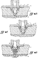
- the worker aligns the attachment plate 1 with the desired location on the insulation panel 57. He then manually pushes the tool 55 and attachment plate such that the attachment plate second end 5 penetrates the insulation panel. The fins 43 cut the insulation panel and aid in the penetration process. Manual pushing continues until the adapter stabilizing flange 65 and the rest 69 contact the insulation panel exposed surface 73, Fig. 6B. At that point, the attachment plate first end 2 is flush with the exposed surface 73 of the insulation panel, and the attachment plate second end 5 is in contact with the building substrate 59.
- the worker continues to push the tool 55 toward the insulation panel 57. That action causes the tool 55, including its muzzle 75, to move toward the attachment plate 1 relative to the adapter 63, Fig. 6C.
- the tool muzzle 75 advances to contact the second fingers 49 of the double fingers 45.
- the muzzle 75 bends the second fingers downwardly into the counterbore 53 and flat against the first fingers 47.
- the first fingers 47 bend slightly outwardly.
- the tool advances until the muzzle free end is close to the adapter plate dished surface 28. At that point, the tool bottoms out relative to the adapter.
- the motion of the tool relative to the adapter energizes the tool electronic firing system through the adapter spring loaded mounting system. The workman is then able to fire the tool.
- a driving ram in the muzzle passes through the tool muzzle to force a collating ring 79 and a nail 77 into the recess 29 of the attachment plate 1.
- the collating ring 79 becomes compressed within the recess and locks to the attachment plate around the nail by radial compression and frictional forces of the recess internal diameter 27.
- the nail 77 passes through the passage 31 and becomes embedded in the substrate 59, thus installing the attachment plate to the substrate and clamping the associated region of the insulation panel 57 to the substrate.
- the first fingers 47 absorb shock from the tool 55 during firing and lessen any potential damage to the second fingers 49, which are bent over by and in contact with the muzzle 75.
- a series of coatings 81 are spread on the insulation panel exposed surface 73 to provide solid wall foundation and texture.
- the double fingers 45 act to seal the counterbore 53 from excessive coating penetration and adhesion. Any coating 81 that does enter the counterbore 53 serves to anchor the adjacent coating and enable it to resist outward and shear forces. Some coating material also enters the annular chamber 51 and fills the holes 9 in the washer 7 to provide additional adhesion of the coating over the insulation panel. Consequently, the finished surface of the building wall provides a smooth and dimple free appearance as well as a strong bond to the insulation panel.
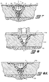
- the attachment plate is capable of accommodating insulation panels of varying thicknesses.
- an insulation panel 57A has a thickness greater than the nominal thickness of the insulation panel 57 of Figs. 9-7. Consequently, when the worker has fully penetrated the attachment plate 1 manually into the insulation panel 57A with his tool 55, the second end 5 of the attachment plate does not contact the substrate 59. When the worker fires the tool, the force of the driving ram on the nail will further penetrate the attachment plate into the insulation panel such that the attachment plate second end 5 does contact the substrate 59. As a result, the attachment plate washer 7 comes to rest below the insulation panel exposed surface 73A, Fig. 8A.
- the insulation panel 57B has a thickness less than the nominal thickness of the insulation panel 57 of Figs. 4-7.
- the second end 5 of the attachment plate 1 contacts the substrate 59 before the adapter 63 of the setting tool contacts the insulation panel exposed surface 73B.
- the driving ram forces the attachment plate tabs 41 to bend until the surface of the attachment plate first end 2 is flush with the insulation panel exposed surface 73B, Fig. 9A.
- the surface of the attachment plate first end does not protrude above the insulation panel exposed surface 73B. Rather, the surface of the attachment plate first end is always flush with or slightly below the insulation panel exposed surface.
- a modified attachment plate 83 is depicted that is generally similar to the attachment plate 1 described above in conjunction with Figs. 1-9.
- the attachment plate 83 is fabricated with a solid thin cylindrical band 85 upstanding from the transverse surface 24' at the end of the inner diameter 23' of the first section 13' of the tubular member 11'.
- the fingers 87 are bendable by respective living hinges to the band 85.
- the fingers 87 extend radially toward the longitudinal axis 3' and lie generally coplanar with the attachment plate first end 2'.
- the attachment plate 83 is identical to the attachment plate 1.
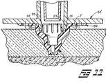
- Fig. 11 shows a further modified attachment plate 89.
- the attachment plate 89 has a frusto-conical surface 91 for the central opening of the washer 7' and for the inner diameter 23' of the first section 13' of the tubular member 11'. Accordingly, the cross section of the annular chamber 93 has a generally triangular shape.
- the pilot 95 of the setting tool adapter 63' has a frusto-conical exterior surface 97.
Landscapes
- Engineering & Computer Science (AREA)
- Mechanical Engineering (AREA)
- Architecture (AREA)
- Structural Engineering (AREA)
- Combustion & Propulsion (AREA)
- Civil Engineering (AREA)
- Chemical & Material Sciences (AREA)
- Physics & Mathematics (AREA)
- Acoustics & Sound (AREA)
- Electromagnetism (AREA)
- Joining Of Building Structures In Genera (AREA)
- Conveying And Assembling Of Building Elements In Situ (AREA)
- Connection Of Plates (AREA)
Applications Claiming Priority (2)
| Application Number | Priority Date | Filing Date | Title |
|---|---|---|---|
| US369354 | 1995-01-06 | ||
| US08/369,354 US5607272A (en) | 1995-01-06 | 1995-01-06 | Attachment plate for insulation panels |
Publications (3)
| Publication Number | Publication Date |
|---|---|
| EP0721032A2 true EP0721032A2 (fr) | 1996-07-10 |
| EP0721032A3 EP0721032A3 (fr) | 1997-04-16 |
| EP0721032B1 EP0721032B1 (fr) | 2002-04-03 |
Family
ID=23455123
Family Applications (1)
| Application Number | Title | Priority Date | Filing Date |
|---|---|---|---|
| EP95309336A Expired - Lifetime EP0721032B1 (fr) | 1995-01-06 | 1995-12-21 | Rondelle de fixation |
Country Status (4)
| Country | Link |
|---|---|
| US (3) | US5607272A (fr) |
| EP (1) | EP0721032B1 (fr) |
| CA (1) | CA2164186C (fr) |
| DE (1) | DE69526196T2 (fr) |
Cited By (1)
| Publication number | Priority date | Publication date | Assignee | Title |
|---|---|---|---|---|
| FR2786420A1 (fr) * | 1998-11-30 | 2000-06-02 | Spit Soc Prospect Inv Techn | Procede de pose d'une embase de fixation de piece et outil de fixation pour la mise en oeuvre du procede |
Families Citing this family (34)
| Publication number | Priority date | Publication date | Assignee | Title |
|---|---|---|---|---|
| DE19619318A1 (de) * | 1996-05-14 | 1997-11-20 | Hilti Ag | Dämmstoffbefestigungselement |
| US5908278A (en) * | 1997-08-07 | 1999-06-01 | Illinois Tool Works Inc. | Stress plate with depending sleeve |
| FR2773596B1 (fr) | 1998-01-14 | 2000-02-11 | Spit Soc Prospect Inv Techn | Embase de fixation de piece |
| US6145272A (en) * | 1999-04-12 | 2000-11-14 | Tomaini; John C. | Insulation fastener disk method for fastening insulation |
| FR2800813B1 (fr) * | 1999-11-10 | 2002-02-15 | Prospection & Inventions | Embase de fixation d'une piece perforee a un support |
| US6425720B1 (en) * | 2000-02-28 | 2002-07-30 | Hy Kramer | Substrate attaching member |
| AT411077B (de) * | 2000-12-01 | 2003-09-25 | Franz Stransky Ges M B H A 115 | Verfahren zum befestigen von wärmedämmplatten an einer wand oder einer decke |
| US6406243B1 (en) * | 2001-03-21 | 2002-06-18 | Illinois Tool Works Inc. | Washer with dome profile |
| US20030072634A1 (en) * | 2001-09-19 | 2003-04-17 | K&R Corporation And Simplex Nails | Non-magnetic fastener with magnetic locking nail and two-stage hammer apparatus |
| DE10229141C1 (de) * | 2002-06-28 | 2003-07-31 | Hilti Ag | Befestigungselement |
| US7093338B2 (en) * | 2003-10-31 | 2006-08-22 | Powers Fasteners, Inc. | Method and apparatus for fixing assembly having resilient tool connection |
| US7207762B2 (en) * | 2003-12-23 | 2007-04-24 | Federal-Mogul World Wide, Inc. | Push-on screw-off attachment device |
| WO2006019786A1 (fr) * | 2004-07-19 | 2006-02-23 | James Murtha | Adaptateur de profondeur et doigtier préréglés pour vis et clous lors de l'installation d'une plaque de plâtre |
| ES2261026B1 (es) * | 2004-08-03 | 2007-11-01 | Pablo Albero Verdu | Dispositivo para la condena de puertas. |
| CA2613502A1 (fr) * | 2005-06-24 | 2007-01-04 | James Murtha | Cloueuse et systeme d'entrainement et de visee de goujons incorpore dans une cloueuse |
| US8756871B1 (en) * | 2006-07-18 | 2014-06-24 | Jeffrey K. Johnson | Method and apparatus for attaching a supported addition to a finished building |
| DE102007058773A1 (de) * | 2007-12-06 | 2009-06-10 | Fischerwerke Gmbh & Co. Kg | Dämmstoffhalter |
| US8413740B2 (en) * | 2008-07-23 | 2013-04-09 | Rodenhouse, Inc. | Fastener gun washer assembly holding device and method of use |
| DK2350467T3 (en) * | 2008-11-25 | 2017-01-16 | Itw Australia Pty Ltd | CONFIRMATION FOR INSULATION |
| WO2012012492A1 (fr) * | 2010-07-20 | 2012-01-26 | Handy & Harman | Système de fixation d'isolation de toit |
| KR101077844B1 (ko) * | 2011-04-29 | 2011-11-07 | 김재옥 | 건축용 석재 받침앵글의 지지장치 |
| DE202012011890U1 (de) * | 2012-12-12 | 2014-03-13 | Illinois Tool Works Inc. | Dübelvorrichtung zur Befestigung von Dämmmaterial |
| DE102013004392A1 (de) * | 2013-03-13 | 2014-09-18 | Sfs Intec Holding Ag | Tülle und Befestigungselement zum Befestigen einer Materialschicht |
| US9939004B2 (en) * | 2014-09-17 | 2018-04-10 | Arconic Inc | Coated fasteners with conforming seals |
| JP6516140B2 (ja) * | 2015-01-13 | 2019-05-22 | 住ベシート防水株式会社 | 固定具およびシート防水構造 |
| JP6516141B2 (ja) * | 2015-01-13 | 2019-05-22 | 住ベシート防水株式会社 | 固定具およびシート防水構造 |
| CA2945276C (fr) * | 2015-10-16 | 2024-05-28 | Brian Keith Orchard | Magasin de fixations a pince |
| DE102016125660A1 (de) * | 2016-12-23 | 2018-06-28 | Böllhoff Verbindungstechnik GmbH | Befestigungseinleger für ein Bauteil aus Kunststoff-, Schaum- oder Verbundmaterial |
| US10960525B2 (en) * | 2018-06-15 | 2021-03-30 | National Nail Corporation | Hybrid cordless cap tool |
| JP6711492B2 (ja) * | 2018-11-16 | 2020-06-17 | 住ベシート防水株式会社 | 固定具およびシート防水構造 |
| JP6711491B2 (ja) * | 2018-11-16 | 2020-06-17 | 住ベシート防水株式会社 | 固定具およびシート防水構造 |
| AT522756B1 (de) * | 2019-07-12 | 2022-04-15 | Austrotherm Gmbh | Platte zum Befestigen von Wärmedämmplatten |
| EP4187034A1 (fr) * | 2021-11-30 | 2023-05-31 | Hilti Aktiengesellschaft | Procédé et dispositif de fixation d'un composant à un substrat |
| US20230279662A1 (en) * | 2022-03-07 | 2023-09-07 | Bmic Llc | Fastener systems for roof structures |
Family Cites Families (32)
| Publication number | Priority date | Publication date | Assignee | Title |
|---|---|---|---|---|
| US2307348A (en) * | 1941-04-14 | 1943-01-05 | Anderson Chester Sig | Fastening device |
| US2334406A (en) * | 1942-02-27 | 1943-11-16 | Crescent Brass & Pin Company | Roofing and packing nail |
| US2769333A (en) * | 1952-12-15 | 1956-11-06 | George P Reintjes | Wall facing |
| US3348751A (en) * | 1965-08-02 | 1967-10-24 | Olin Mathieson | Power operated piston tool |
| DE1603902A1 (fr) * | 1965-09-02 | |||
| US3473718A (en) * | 1966-11-21 | 1969-10-21 | Birmingham Small Arms Co Ltd | Explosive-actuated tools |
| US3559272A (en) * | 1968-09-16 | 1971-02-02 | Omark Industries Inc | Driving cap for drivepin, and tool and method therefor |
| US4361997A (en) * | 1980-02-25 | 1982-12-07 | Textron Inc. | Fastener plate and assembly |
| US4380413A (en) * | 1980-11-03 | 1983-04-19 | Illinois Tool Works Inc. | Load-distributive washer for use with compressible material |
| US4545270A (en) * | 1981-05-07 | 1985-10-08 | Illinois Tool Works Inc. | Device for assuring predetermined joint loading in roof insulation assemblies |
| US4630984A (en) * | 1984-01-27 | 1986-12-23 | Elco Industries, Inc. | Assembly for fastening a layer of compressible material to a rigid member |
| DE3427616A1 (de) * | 1984-07-26 | 1986-01-30 | Hilti Ag, Schaan | Pulverkraftbetriebenes bolzensetzgeraet |
| US4606168A (en) * | 1984-11-29 | 1986-08-19 | Fuhrer John P R | Suspended insulated building exterior cladding |
| US4703883A (en) * | 1985-11-12 | 1987-11-03 | Alfonaso Losada | Fastener assembly |
| US4663910A (en) * | 1986-03-17 | 1987-05-12 | Illinois Tool Works Inc. | Washer for roofing insulation |
| US4757661A (en) * | 1986-03-17 | 1988-07-19 | Illinois Tool Works, Inc. | Washer with axial ribs |
| US4773581A (en) * | 1986-06-13 | 1988-09-27 | Hitachi Koki Company, Ltd. | Combustion gas powered tool |
| US5066181A (en) * | 1987-01-21 | 1991-11-19 | Stadler Ag | Attachment element with large washer |
| FR2610375A1 (fr) * | 1987-01-30 | 1988-08-05 | Prospection & Inventions | Tampon de fixation de panneau |
| US4884932A (en) * | 1987-05-01 | 1989-12-05 | Meyer Eugene M | Decking insulation fastener |
| US4862664A (en) * | 1987-12-23 | 1989-09-05 | Romine Robert L | Roofing fastener for fastener assembly and roof assemblies |
| US5255485A (en) * | 1988-08-25 | 1993-10-26 | Stuart H. Lemke | Apparatus and method for installing roofing fasteners |
| AT392331B (de) * | 1989-06-09 | 1991-03-11 | Sfs Stadler Holding Ag | Befestigungselement zur fixierung von isolierbahnen oder -platten auf einem festen unterbau |
| US4959938A (en) * | 1989-08-28 | 1990-10-02 | Caro Charles J De | Non-seating plate/fastener assembly |
| DE3931833A1 (de) * | 1989-09-23 | 1991-04-04 | Hilti Ag | Befestigungselement zum befestigen von isolationsplatten |
| EP0424941B1 (fr) * | 1989-10-27 | 1994-01-05 | Hitachi Koki Co., Ltd. | Appareil pour enfoncer des attaches actionné par une force de combustion |
| US5082412A (en) * | 1990-12-03 | 1992-01-21 | Illinois Tool Works Inc. | Roofing washer |
| DE4041819A1 (de) * | 1990-12-24 | 1992-06-25 | Hilti Ag | Befestigungselement fuer isolationsplatten |
| US5118235A (en) * | 1991-02-11 | 1992-06-02 | Illinois Tool Works Inc. | Washer with integral flap and fastening assembly combining fastener with such washer |
| US5069340A (en) * | 1991-03-05 | 1991-12-03 | Illinois Tool Works Inc. | Strip of collated fasteners for fastener-driving tool |
| US5217339A (en) * | 1992-06-30 | 1993-06-08 | Performance Building Products, Inc. | Non-seating plate/fastener assembly |
| DE4329806A1 (de) * | 1993-09-03 | 1995-03-09 | Fischer Artur Werke Gmbh | Halteelement für die Befestigung von Dämmstoffplatten |
-
1995
- 1995-01-06 US US08/369,354 patent/US5607272A/en not_active Expired - Lifetime
- 1995-11-30 CA CA002164186A patent/CA2164186C/fr not_active Expired - Fee Related
- 1995-12-21 DE DE69526196T patent/DE69526196T2/de not_active Expired - Fee Related
- 1995-12-21 EP EP95309336A patent/EP0721032B1/fr not_active Expired - Lifetime
-
1996
- 1996-09-05 US US08/708,520 patent/US5688092A/en not_active Expired - Lifetime
- 1996-09-05 US US08/708,444 patent/US5772381A/en not_active Expired - Lifetime
Cited By (5)
| Publication number | Priority date | Publication date | Assignee | Title |
|---|---|---|---|---|
| FR2786420A1 (fr) * | 1998-11-30 | 2000-06-02 | Spit Soc Prospect Inv Techn | Procede de pose d'une embase de fixation de piece et outil de fixation pour la mise en oeuvre du procede |
| EP1005959A1 (fr) * | 1998-11-30 | 2000-06-07 | Societe De Prospection Et D'inventions Techniques Spit | Procédé de pose d'une embase de fixation de pièce et outil de fixation pour la mise en oeuvre du procédé |
| AU728640B2 (en) * | 1998-11-30 | 2001-01-11 | Societe De Prospection Et D'inventions Techniques S.P.I.T. | Method for setting a piece fastening base plate and fastening tool for carrying out the method |
| US6324743B1 (en) | 1998-11-30 | 2001-12-04 | Societe De Prospection Et D'inventions Techniques Spit | Method for setting a piece fastening base plate |
| US6371350B2 (en) | 1998-11-30 | 2002-04-16 | Societe De Prospection Et D'inventions Techniques Spit | Fastening tool for setting a piece fastening base plate |
Also Published As
| Publication number | Publication date |
|---|---|
| CA2164186A1 (fr) | 1996-07-07 |
| US5607272A (en) | 1997-03-04 |
| EP0721032B1 (fr) | 2002-04-03 |
| DE69526196T2 (de) | 2002-10-10 |
| EP0721032A3 (fr) | 1997-04-16 |
| US5772381A (en) | 1998-06-30 |
| CA2164186C (fr) | 1999-08-03 |
| US5688092A (en) | 1997-11-18 |
| DE69526196D1 (de) | 2002-05-08 |
Similar Documents
| Publication | Publication Date | Title |
|---|---|---|
| EP0721032B1 (fr) | Rondelle de fixation | |
| CA2151668C (fr) | Ensemble clou-gaine d'assemblage et bande de clous assembles | |
| CA2362127C (fr) | Agrafe pour reparation de panneau mural, procede et kit de reparation de panneau mural | |
| EP0576034B1 (fr) | Clou de fixation | |
| CA1290600C (fr) | Fixation avec rondelle grande dimension | |
| EP1234121B1 (fr) | Element de fixation capable de percer le metal | |
| US7207761B2 (en) | Pin fastener for achieving metal-to-metal connections | |
| US3977142A (en) | Floor nail | |
| WO1988007139A1 (fr) | Organe de stabilisation destine a etre utilise avec des elements de structure | |
| US4693438A (en) | Electrical box retainer | |
| NZ248798A (en) | Impact drivable fastener having a tapered helical fluted section with ribs and flutes increasing from zero value adjacent to tip end towards head end | |
| US6088986A (en) | Wallboard repair clip, method of repairing wallboard, kit for repairing wallboard, and method of accessing the interior of hollow walls | |
| GB2124318A (en) | A screw threaded fastener and fastened assembly | |
| US20080247843A1 (en) | Fastening system | |
| AU2005203575B2 (en) | Fastening system for attaching metal studs to metal track | |
| CA2519202C (fr) | Dalle de plafond | |
| US20090232620A1 (en) | Pneumatic fastener for metal studs and related method | |
| US20060283106A1 (en) | Framing connector | |
| AU666579B2 (en) | Impact drivable fastener | |
| EP4441304A1 (fr) | Procédé et dispositif de fixation d'un composant sur une structure de support | |
| AU1620588A (en) | Stabiliser for use with structural elements | |
| EP1790863A1 (fr) | Élément de fixation |
Legal Events
| Date | Code | Title | Description |
|---|---|---|---|
| PUAI | Public reference made under article 153(3) epc to a published international application that has entered the european phase |
Free format text: ORIGINAL CODE: 0009012 |
|
| AK | Designated contracting states |
Kind code of ref document: A2 Designated state(s): BE DE FR GB SE |
|
| PUAL | Search report despatched |
Free format text: ORIGINAL CODE: 0009013 |
|
| 17P | Request for examination filed |
Effective date: 19970103 |
|
| AK | Designated contracting states |
Kind code of ref document: A3 Designated state(s): BE DE FR GB SE |
|
| 17Q | First examination report despatched |
Effective date: 19991108 |
|
| GRAG | Despatch of communication of intention to grant |
Free format text: ORIGINAL CODE: EPIDOS AGRA |
|
| GRAG | Despatch of communication of intention to grant |
Free format text: ORIGINAL CODE: EPIDOS AGRA |
|
| GRAH | Despatch of communication of intention to grant a patent |
Free format text: ORIGINAL CODE: EPIDOS IGRA |
|
| GRAH | Despatch of communication of intention to grant a patent |
Free format text: ORIGINAL CODE: EPIDOS IGRA |
|
| REG | Reference to a national code |
Ref country code: GB Ref legal event code: IF02 |
|
| GRAA | (expected) grant |
Free format text: ORIGINAL CODE: 0009210 |
|
| AK | Designated contracting states |
Kind code of ref document: B1 Designated state(s): BE DE FR GB SE |
|
| REF | Corresponds to: |
Ref document number: 69526196 Country of ref document: DE Date of ref document: 20020508 |
|
| ET | Fr: translation filed | ||
| PG25 | Lapsed in a contracting state [announced via postgrant information from national office to epo] |
Ref country code: GB Free format text: LAPSE BECAUSE OF NON-PAYMENT OF DUE FEES Effective date: 20021221 |
|
| PLBE | No opposition filed within time limit |
Free format text: ORIGINAL CODE: 0009261 |
|
| STAA | Information on the status of an ep patent application or granted ep patent |
Free format text: STATUS: NO OPPOSITION FILED WITHIN TIME LIMIT |
|
| 26N | No opposition filed |
Effective date: 20030106 |
|
| GBPC | Gb: european patent ceased through non-payment of renewal fee |
Effective date: 20021221 |
|
| PGFP | Annual fee paid to national office [announced via postgrant information from national office to epo] |
Ref country code: FR Payment date: 20051216 Year of fee payment: 11 |
|
| PGFP | Annual fee paid to national office [announced via postgrant information from national office to epo] |
Ref country code: SE Payment date: 20051227 Year of fee payment: 11 |
|
| PGFP | Annual fee paid to national office [announced via postgrant information from national office to epo] |
Ref country code: DE Payment date: 20060131 Year of fee payment: 11 |
|
| PGFP | Annual fee paid to national office [announced via postgrant information from national office to epo] |
Ref country code: BE Payment date: 20060202 Year of fee payment: 11 |
|
| PG25 | Lapsed in a contracting state [announced via postgrant information from national office to epo] |
Ref country code: SE Free format text: LAPSE BECAUSE OF NON-PAYMENT OF DUE FEES Effective date: 20061222 |
|
| PG25 | Lapsed in a contracting state [announced via postgrant information from national office to epo] |
Ref country code: BE Free format text: LAPSE BECAUSE OF NON-PAYMENT OF DUE FEES Effective date: 20061231 |
|
| PG25 | Lapsed in a contracting state [announced via postgrant information from national office to epo] |
Ref country code: DE Free format text: LAPSE BECAUSE OF NON-PAYMENT OF DUE FEES Effective date: 20070703 |
|
| EUG | Se: european patent has lapsed | ||
| REG | Reference to a national code |
Ref country code: FR Ref legal event code: ST Effective date: 20070831 |
|
| BERE | Be: lapsed |
Owner name: ILLINOIS *TOOL WORKS INC. Effective date: 20061231 |
|
| PG25 | Lapsed in a contracting state [announced via postgrant information from national office to epo] |
Ref country code: FR Free format text: LAPSE BECAUSE OF NON-PAYMENT OF DUE FEES Effective date: 20070102 |