EP0721035B1 - Schlüssel und Zylinderschlossanlage - Google Patents
Schlüssel und Zylinderschlossanlage Download PDFInfo
- Publication number
- EP0721035B1 EP0721035B1 EP95119473A EP95119473A EP0721035B1 EP 0721035 B1 EP0721035 B1 EP 0721035B1 EP 95119473 A EP95119473 A EP 95119473A EP 95119473 A EP95119473 A EP 95119473A EP 0721035 B1 EP0721035 B1 EP 0721035B1
- Authority
- EP
- European Patent Office
- Prior art keywords
- key
- plug
- pins
- cylinder
- pin
- Prior art date
- Legal status (The legal status is an assumption and is not a legal conclusion. Google has not performed a legal analysis and makes no representation as to the accuracy of the status listed.)
- Expired - Lifetime
Links
- 230000013011 mating Effects 0.000 claims 1
- 238000000926 separation method Methods 0.000 description 5
- 230000037431 insertion Effects 0.000 description 4
- 238000003780 insertion Methods 0.000 description 4
- 239000000470 constituent Substances 0.000 description 2
- 230000014759 maintenance of location Effects 0.000 description 2
- 230000002441 reversible effect Effects 0.000 description 2
- 238000000605 extraction Methods 0.000 description 1
- 238000003754 machining Methods 0.000 description 1
- 230000000284 resting effect Effects 0.000 description 1
Images




Classifications
-
- E—FIXED CONSTRUCTIONS
- E05—LOCKS; KEYS; WINDOW OR DOOR FITTINGS; SAFES
- E05B—LOCKS; ACCESSORIES THEREFOR; HANDCUFFS
- E05B27/00—Cylinder locks or other locks with tumbler pins or balls that are set by pushing the key in
- E05B27/0039—Cylinder locks or other locks with tumbler pins or balls that are set by pushing the key in with pins which slide and rotate about their axis
Definitions
- This invention relates to a key and cylinder lock unit.
- Locks comprising a cylinder forming the lock body and a plug housed in the cylinder and provided with a radially projecting pawl for operating a bolt.
- the cylinder and plug comprise a plurality of radial cylindrical recesses in which pins formed in two parts are housed and can slide axially.
- the axial position of the pins is such that the separation surface between their two constituent parts does not coincide with the surface of discontinuity between the plug and cylinder, with the result that the pins act as locking members for preventing the plug rotating relative to the cylinder.
- the key is inserted into a corresponding seat provided in the plug, it causes the various pins to move axially in accordance with its pattern, such as to make the separation surface between the two constituent parts of each pin coincide with the surface of discontinuity between the plug and cylinder, to enable the plug to be rotated by said key.
- patterned keys consisting of a key comprising along one edge a series of notches, which determine, by supporting them, the correct positioning of pins present in the lock and urged against said notches by springs.
- This type of key is advantageous in that if for example the notches are formed by a cutter the axis of which is inclined to the longitudinal axis of the shaft, they are able to cause each pin to move not only axially but to also rotate, hence considerably increasing the number of possible different patterns, to the advantage of security.
- this type of key also has certain drawbacks, and in particular enables the key pattern to be read on sight by an expert, hence enabling it to be duplicated even without the original key being available.
- this type of key has one or both its edges toothed, such that it may damage clothing, bags and surfaces in general with which the key comes into contact.
- Another kwown type of key uses a flat shank with its major surface and possibly its other surfaces comprising recesses for housing the ends of the pins which lock the cylinder to the plug. As the depth of each recess varies, the axial position of the respective pin also varies, and only if the key pattern corresponds to that particular lock can its insertion into the plug cause this latter to be released and to be able to be rotated relative to the cylinder.
- This known type of key has a smooth edge and therefore cannot damage bags or clothing, and in addition makes it more difficult to identify the pattern merely by viewing the key.
- it can cause the pins only to translate axially but not to rotate, and consequently offers a relatively limited number of different combinations, and hence an unsatisfactory degree of security.
- An object of the invention is to obviate the aforesaid drawbacks by providing a key and cylinder lock unit having a high degree of security.
- a further object of the invention is to provide a unit in which for releasing the plug from the cylinder the pins are required not only to move axially but also to rotate.
- a further object of the invention is to provide a unit in which the key pattern cannot be easily identified by direct viewing.
- a further object of the invention is to provide a unit in which it is extremely difficult to duplicate the key, in contrast to known keys, which can be cut by a file or drill, according to the type.
- a further object of the invention is to provide a unit in which key duplication requires machining along three axes.
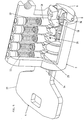
- the unit according to the invention comprises a lock, indicated overall by 2, and a key, indicated overall by 4.
- the lock comprises a plug 6 housed in a cylindrical cavity of a cylinder 8, of the type for example commonly known as a "European cylinder", ie with a cylindrical portion housing the plug 6 and a radial appendix housing the pin mechanism for locking and releasing the plug.
- the cylinder 8 comprises a plurality of cylindrical recesses 10 (five in the illustrated example) having their axes mutually parallel and perpendicular to the axis of the cylindrical cavity housing the plug 6, which also comprises a like number of cylindrical recesses 12 of the same diameter, these being coaxially aligned with the corresponding recesses in the cylinder 8 when the plug 6 is in a certain precise angular position.
- the five recesses 12 of the plug 6 open into a longitudinal seat 14, also provided in the plug 6, for the insertion of the key 4.
- Pairs of pins 16 and counterpins 18 are free to slide axially in and rotate within each pair of aligned recesses 10,12 and are in mutual contact along a castellated surface.
- Each counterpin 18 is associated with a spring 22 also housed in the corresponding cylindrical recess 10 and interposed between a disc 20, resting on said counterpin 18, and a cap 24 applied to the end of the same recess 10.
- the purpose of the spring 22 is to urge the pin-counterpin pair towards the longitudinal seat 14 until a retention appendix 26 emerging radially from the pin 16 encounters a shoulder 28 of a longitudinal channel 29 provided in the body of the plug between the adjacent pins 16, its purpose being to limit the rotation of the pin-counterpin pair between the two walls of said channel 29.
- each pin 16 distant from the counterpin 18 is provided with an eccentric appendix 30, the dimensions of the various parts concerned being such that when each retention appendix 26 rests against the corresponding shoulder 28, the eccentric appendix 30 of each pin 16 projects into the longitudinal seat 14 for the key 4.
- the cavity in the cylinder 8 which houses the plug 6 is perfectly cylindrical, the corresponding lateral surface of the plug has a characteristic stepped shape compatible with the castellated shape of the surface of separation between each pin 16 and the relative counterpin 18 (see Figures 2,5,6).
- the key 4 comprises a handgrip 33 and a shank 34 of overall parallelepiped section, with a chamfered tip and with each major face comprising a continuous channel 36 of width just greater than the diameter of the eccentric appendices 30.
- the channel 36 it would be sufficient for the channel 36 to be provided on only one face of the key, however the presence of two channels symmetrical about the longitudinal axis of the key makes this reversible.
- the channel 36 which is open and is slightly flared at the end of the key 4, is formed from a succession of several rectilinear portions arranged at an angle to each other so as to cause the channel to assume a broken-line configuration.
- the depth of the various portions is not constant and consequently the junction points of adjacent portions are at different distances from the outer face of the key.
- each pin-counterpin pair is such that the separation surface between the two exactly prolongs the stepped lateral surface of the plug 6, to hence enable this latter to be rotated by the key 4.
- extraction of the key 4 causes the various pin-counterpin pairs to move in the reverse direction, and when the key has been completely extracted all the pairs lie at the same angle corresponding to the position of the open end of the channel 36.
- This position is totally different from that set by the key 4 when completely inserted, and maintains the plug 6 locked to the cylinder 8.
- each pin 16 comprises in its lateral surface a rectilinear groove 38, which for that angular position of each pin-counterpin pair established by the insertion of the key 4 is in phase with the others, to allow engagement by a further pin 40 movable axially between a position totally housed within the plug 6 and a position emerging from said plug to engage a front-standing recess 42 provided in the cylinder 8.
- the key and cylinder lock unit according to the invention is considerably advantageous, and in particular:
Landscapes
- Lock And Its Accessories (AREA)
- Snaps, Bayonet Connections, Set Pins, And Snap Rings (AREA)
- Electrophonic Musical Instruments (AREA)
- Fittings On The Vehicle Exterior For Carrying Loads, And Devices For Holding Or Mounting Articles (AREA)
- Details Of Connecting Devices For Male And Female Coupling (AREA)
- Reciprocating Pumps (AREA)
Claims (10)
- Schlüssel- und Zylinderschlossanlage, bei der das Schloss (2) einen Kern (6) und einen Zylinder (8) umfaßt, der mit einem radialen Vorsprung versehen ist, wobei der Kern und der Vorsprung mit einer Vielzahl von im wesentlichen radialen zylindrischen Ausnehmungen (12, 10) versehen ist, die Stifte (16, 18) aufnehmen, die aus zwei Teilen bestehen, die durch eine Oberfläche getrennt sind, damit sie passen, geeignet geformt sind und, wenn sie eine vorgegebene axiale und Drehposition einnehmen, es den Kern (6) ermöglichen, sich relativ zum Zylinder (8) zu drehen, gesteuert von einem Schlüssel, der in einen entsprechenden Sitz (14) gesteckt ist, der in dem Kern (6) vorgesehen ist, und mit den Enden der besagten Stifte zusammenwirkt, die sich in den besagten Sitz erstrecken, dadurch gekennzeichnet, dassdas Ende der besagten Stifte, welche sich in den besagten Sitz (14) erstrecken, mit einem exzentrischen Ansatz (30) versehen ist,der Schlüssel (4) in der Fläche, die den besagten Stiften (16, 18) gegenüberliegt, einen kontinuierlichen Kanal (36) aufweist, der zu dem Ende des Schlüsselschaftes (34) offen ist und eine Breite und einen Querschnitt aufweist, der zur Aufnahme der Ansätze (30) der Stifte geeignet ist, und sich längs mit unterschiedlichen Tiefen auf einem nicht rechteckigen Weg erstreckt, wobeidie Form des gesagten Kanals (36) derart ist, dass, wenn der Schlüssel (4) ganz in seinen Sitz (14) gesteckt ist, die axiale und Drehposition jedes Stiftes (16, 18) derart ist, dass der besagte Kern (6) vom Zylinder (8) freigegeben wird.
- Anlage nach Anspruch 1, dadurch gekennzeichnet, dass jeder Stift einen ersten Teil (16) oder tatsächlichen Stift, der von der entsprechenden zylindrischen Ausnehmung (12), die in dem Kern (6) vorgesehen ist, vollständig aufgenommen wird, und einen zweiten Teil (18) oder Gegenstift umfaßt, der von der entsprechenden zylindrischen Ausnehmung (10) aufgenommen wird, die in dem Zylinder (8) vorgesehen ist, welcher Teil von der zugehörigen zylindrischen Ausnehmung (12) des Kerns (6) aufgenommen wird, wenn das Schloss gesperrt ist.
- Anlage nach Anspruch 2, dadurch gekennzeichnet, dass die Oberfläche der Diskontinuität zwischen jedem Stift (16) und dem zugehörigen Gegenstift (18) derart stufenförmig ist, dass die ähnlich geformte Seitenoberfläche des Kerns (6) verlängert wird, wenn das Schloss in seinem geöffneten Zustand ist.
- Anlage nach Anspruch 1, dadurch gekennzeichnet, dass der Kanal (36), der in dem Schlüssel (4) vorgesehen ist, aus mehreren Längsabschnitten gebildet ist, die dem Abstand zwischen den Achsen der Ansätze (30) der Stifte (16) entsprechen, wenn diese ihre Winkelposition einnehmen, in der das Schloss geöffnet ist.
- Anlage nach Anspruch 1, dadurch gekennzeichnet, dass das offene Ende des Kanals (36) konisch erweitert ist.
- Anlage nach Anspruch 1, dadurch gekennzeichnet, dass in den einander gegenüberliegenden Oberflächen seines Schaftes (34) der Schlüssel (4) zwei zur Längsachse des besagten Schaftes symmetrische Kanäle (36) umfaßt.
- Anlage nach Anspruch 2, dadurch gekennzeichnet, dass jedem Stift (16) ein radialer Ansatz (26) zugeordnet ist, der die axiale und Drehbewegung des besagten Stiftes (16) und des im zugeordneten Gegenstiftes (18) begrenzt.
- Anlage nach Anspruch 7, dadurch gekennzeichnet, dass der Kern (6) einen Längskanal (29) umfaßt, der sämtliche zylindrischen Ausnehmungen (12) quert und zwischen benachbarten Ausnehmungen einen Raum zur Bewegung der besagten radialen Ansätze (26) begrenzt.
- Anlage nach Anspruch 2, dadurch gekennzeichnet, dass in der Seitenoberfläche jedes Stiftes (16) eine Längsnut (38) vorgesehen ist, wobei die Nuten aller Stifte (16) eine solche Winkelposition besitzen, dass, wenn der Schlüssel (4) in das Schloss gesteckt ist, allen besagten Nuten (38) weitere Stifte (49) zum Sperren des Kerns (6) gegenüber dem Zylinder (8) gegenüberliegen.
- Anlage nach Anspruch 9, dadurch gekennzeichnet, dass jeder Stift (40) vollständig von einem entsprechenden Sitz in dem Kern (6) aufgenommen wird, wenn eines seiner Enden von der Nut (38) des entsprechenden Stiftes (16) aufgenommen wird, wobei ein Teil von ihm an seinem anderen Ende von einer entsprechenden Ausnehmung (42) aufgenommen wird, die in dem Zylinder (8) vorgesehen ist, wenn das erste Ende (40) nicht von der Nut (38) aufgenommen wird.
Applications Claiming Priority (2)
| Application Number | Priority Date | Filing Date | Title |
|---|---|---|---|
| ITVE940054 | 1994-12-27 | ||
| IT94VE000054A IT1268687B1 (it) | 1994-12-27 | 1994-12-27 | Unita' di chiave e serratura a cilindro |
Publications (2)
| Publication Number | Publication Date |
|---|---|
| EP0721035A1 EP0721035A1 (de) | 1996-07-10 |
| EP0721035B1 true EP0721035B1 (de) | 1999-03-17 |
Family
ID=11424059
Family Applications (1)
| Application Number | Title | Priority Date | Filing Date |
|---|---|---|---|
| EP95119473A Expired - Lifetime EP0721035B1 (de) | 1994-12-27 | 1995-12-11 | Schlüssel und Zylinderschlossanlage |
Country Status (5)
| Country | Link |
|---|---|
| EP (1) | EP0721035B1 (de) |
| AT (1) | ATE177812T1 (de) |
| DE (1) | DE69508374T2 (de) |
| ES (1) | ES2129742T3 (de) |
| IT (1) | IT1268687B1 (de) |
Families Citing this family (9)
| Publication number | Priority date | Publication date | Assignee | Title |
|---|---|---|---|---|
| DE19859714C1 (de) * | 1998-12-23 | 2000-06-29 | Tiefenthal Schlies Systeme Gmb | Schließzylinder mit Flachschlüssel |
| IT1302951B1 (it) * | 1998-12-28 | 2000-10-10 | Stefano Ficco | Serratura di sicurezza a perni orientati e ralativa chiave di tipotridimensionale. |
| US20090193862A1 (en) * | 2008-02-05 | 2009-08-06 | Talleres De Escoriaza, S.A. | Lock with combination pins of non-circular section and eccentricity capable of being positioned in rotation and lock key with combination indentations difficult to reproduce fraudulently |
| ES2368543B1 (es) * | 2008-12-11 | 2012-06-04 | Talleres De Escoriaza, S.A. | Llave de cerradura con huellas de combinación de difícil reproducción fraudulenta. |
| ES2337222B1 (es) * | 2008-02-05 | 2011-01-07 | Talleres De Escoriaza, S.A. | "cerradura con pitones de combinacion de seccion no circular y excentricidad posicionable en rotacion". |
| RU2474659C1 (ru) * | 2011-05-27 | 2013-02-10 | Общество С Ограниченной Ответственностью "Инвек" | Цилиндровый замок |
| CN103883168B (zh) * | 2014-04-10 | 2016-06-01 | 陈小仁 | 一种隐藏式旋转锁芯和开启钥匙 |
| CN104806078B (zh) * | 2015-04-30 | 2017-04-05 | 陈小仁 | 一种双旋转锁和开启钥匙的组合 |
| CN109723287B (zh) * | 2019-02-02 | 2024-01-16 | 文江洪 | 超c类锁芯 |
Family Cites Families (1)
| Publication number | Priority date | Publication date | Assignee | Title |
|---|---|---|---|---|
| SE459432B (sv) * | 1986-01-31 | 1989-07-03 | Widen Innovation Ab | Cylinderlaas samt tillhaallare och nyckelblad foer anvaendning i kombination med detta |
-
1994
- 1994-12-27 IT IT94VE000054A patent/IT1268687B1/it active IP Right Grant
-
1995
- 1995-12-11 EP EP95119473A patent/EP0721035B1/de not_active Expired - Lifetime
- 1995-12-11 DE DE69508374T patent/DE69508374T2/de not_active Expired - Lifetime
- 1995-12-11 AT AT95119473T patent/ATE177812T1/de not_active IP Right Cessation
- 1995-12-11 ES ES95119473T patent/ES2129742T3/es not_active Expired - Lifetime
Also Published As
| Publication number | Publication date |
|---|---|
| ATE177812T1 (de) | 1999-04-15 |
| ITVE940054A1 (it) | 1996-06-27 |
| IT1268687B1 (it) | 1997-03-06 |
| DE69508374D1 (de) | 1999-04-22 |
| ES2129742T3 (es) | 1999-06-16 |
| DE69508374T2 (de) | 1999-09-09 |
| EP0721035A1 (de) | 1996-07-10 |
| ITVE940054A0 (it) | 1994-12-27 |
Similar Documents
| Publication | Publication Date | Title |
|---|---|---|
| EP0605932B1 (de) | Verriegelungsvorrichtung | |
| US4103526A (en) | Pin tumbler lock | |
| CA2191217C (en) | Lock assembly with locking bar | |
| KR940006501B1 (ko) | 열쇠를 바꿀 수 있는 실린더 자물쇠(Cylinder Lock) | |
| US4478061A (en) | Cylinder lock | |
| AU690000B2 (en) | Key and cylinder lock unit | |
| US5718136A (en) | Lost key lock-out cylinder | |
| AU672303B2 (en) | A key operable locking mechanism | |
| US5582050A (en) | Cylinder lock-key-combination, a key therefor and a method of producing the key from a key blank | |
| EP0721035A1 (de) | Schlüssel und Zylinderschlossanlage | |
| US4603565A (en) | Cylinder lock embodying at least two rows of tumbler pin bores and opposed rows of locking pins which interact to preclude picking | |
| KR950009224B1 (ko) | 안전자물쇠와 열쇠 | |
| EP0925415B1 (de) | Riegelschloss | |
| EP4379172A1 (de) | Schliesssystem, schlüssel für ein solches system und schlüsselrohling zur herstellung einers solchen schlüssels | |
| EP0065813B1 (de) | Zylinderschloss | |
| EP0161654A2 (de) | Diebstahlsicheres Zylinderschloss, insbesondere für Systeme mit Haupt- und Nebenschlüsseln | |
| EP1921232A2 (de) | Nicht kopierbarer flacher Sicherheitsschlüssel und Sicherheitszylinder | |
| CA1090604A (en) | Plugless pin tumbler cylinder | |
| EP0217586B1 (de) | Zylinderschloss | |
| US3868838A (en) | Cylindrical lock combination changer | |
| GB2266918A (en) | High security lock | |
| WO1996020324A1 (en) | Key and cylinder lock unit | |
| US20260071465A1 (en) | A lock and a method for manufacturing a key | |
| KR20010033135A (ko) | 개량형 실린더 자물쇠 시스템 | |
| GB2041061A (en) | Barrel locks |
Legal Events
| Date | Code | Title | Description |
|---|---|---|---|
| PUAI | Public reference made under article 153(3) epc to a published international application that has entered the european phase |
Free format text: ORIGINAL CODE: 0009012 |
|
| AK | Designated contracting states |
Kind code of ref document: A1 Designated state(s): AT CH DE ES FR GB IT LI NL SE |
|
| 17P | Request for examination filed |
Effective date: 19961104 |
|
| GRAG | Despatch of communication of intention to grant |
Free format text: ORIGINAL CODE: EPIDOS AGRA |
|
| GRAG | Despatch of communication of intention to grant |
Free format text: ORIGINAL CODE: EPIDOS AGRA |
|
| GRAH | Despatch of communication of intention to grant a patent |
Free format text: ORIGINAL CODE: EPIDOS IGRA |
|
| 17Q | First examination report despatched |
Effective date: 19980715 |
|
| GRAH | Despatch of communication of intention to grant a patent |
Free format text: ORIGINAL CODE: EPIDOS IGRA |
|
| GRAA | (expected) grant |
Free format text: ORIGINAL CODE: 0009210 |
|
| ITF | It: translation for a ep patent filed | ||
| AK | Designated contracting states |
Kind code of ref document: B1 Designated state(s): AT CH DE ES FR GB IT LI NL SE |
|
| PG25 | Lapsed in a contracting state [announced via postgrant information from national office to epo] |
Ref country code: SE Free format text: THE PATENT HAS BEEN ANNULLED BY A DECISION OF A NATIONAL AUTHORITY Effective date: 19990317 Ref country code: LI Free format text: LAPSE BECAUSE OF FAILURE TO SUBMIT A TRANSLATION OF THE DESCRIPTION OR TO PAY THE FEE WITHIN THE PRESCRIBED TIME-LIMIT Effective date: 19990317 Ref country code: CH Free format text: LAPSE BECAUSE OF FAILURE TO SUBMIT A TRANSLATION OF THE DESCRIPTION OR TO PAY THE FEE WITHIN THE PRESCRIBED TIME-LIMIT Effective date: 19990317 Ref country code: AT Free format text: LAPSE BECAUSE OF FAILURE TO SUBMIT A TRANSLATION OF THE DESCRIPTION OR TO PAY THE FEE WITHIN THE PRESCRIBED TIME-LIMIT Effective date: 19990317 |
|
| REF | Corresponds to: |
Ref document number: 177812 Country of ref document: AT Date of ref document: 19990415 Kind code of ref document: T |
|
| REG | Reference to a national code |
Ref country code: CH Ref legal event code: EP |
|
| REF | Corresponds to: |
Ref document number: 69508374 Country of ref document: DE Date of ref document: 19990422 |
|
| REG | Reference to a national code |
Ref country code: ES Ref legal event code: FG2A Ref document number: 2129742 Country of ref document: ES Kind code of ref document: T3 |
|
| ET | Fr: translation filed | ||
| REG | Reference to a national code |
Ref country code: CH Ref legal event code: PL |
|
| PLBE | No opposition filed within time limit |
Free format text: ORIGINAL CODE: 0009261 |
|
| STAA | Information on the status of an ep patent application or granted ep patent |
Free format text: STATUS: NO OPPOSITION FILED WITHIN TIME LIMIT |
|
| 26N | No opposition filed | ||
| REG | Reference to a national code |
Ref country code: GB Ref legal event code: IF02 |
|
| PGFP | Annual fee paid to national office [announced via postgrant information from national office to epo] |
Ref country code: DE Payment date: 20121122 Year of fee payment: 18 |
|
| PGFP | Annual fee paid to national office [announced via postgrant information from national office to epo] |
Ref country code: ES Payment date: 20121205 Year of fee payment: 18 Ref country code: IT Payment date: 20121123 Year of fee payment: 18 Ref country code: GB Payment date: 20121122 Year of fee payment: 18 |
|
| PGFP | Annual fee paid to national office [announced via postgrant information from national office to epo] |
Ref country code: NL Payment date: 20121120 Year of fee payment: 18 |
|
| PGFP | Annual fee paid to national office [announced via postgrant information from national office to epo] |
Ref country code: FR Payment date: 20130130 Year of fee payment: 18 |
|
| REG | Reference to a national code |
Ref country code: DE Ref legal event code: R119 Ref document number: 69508374 Country of ref document: DE |
|
| REG | Reference to a national code |
Ref country code: NL Ref legal event code: V1 Effective date: 20140701 |
|
| GBPC | Gb: european patent ceased through non-payment of renewal fee |
Effective date: 20131211 |
|
| REG | Reference to a national code |
Ref country code: FR Ref legal event code: ST Effective date: 20140829 |
|
| REG | Reference to a national code |
Ref country code: DE Ref legal event code: R119 Ref document number: 69508374 Country of ref document: DE Effective date: 20140701 |
|
| PG25 | Lapsed in a contracting state [announced via postgrant information from national office to epo] |
Ref country code: DE Free format text: LAPSE BECAUSE OF NON-PAYMENT OF DUE FEES Effective date: 20140701 Ref country code: NL Free format text: LAPSE BECAUSE OF NON-PAYMENT OF DUE FEES Effective date: 20140701 |
|
| PG25 | Lapsed in a contracting state [announced via postgrant information from national office to epo] |
Ref country code: FR Free format text: LAPSE BECAUSE OF NON-PAYMENT OF DUE FEES Effective date: 20131231 Ref country code: GB Free format text: LAPSE BECAUSE OF NON-PAYMENT OF DUE FEES Effective date: 20131211 |
|
| REG | Reference to a national code |
Ref country code: ES Ref legal event code: FD2A Effective date: 20150327 |
|
| PG25 | Lapsed in a contracting state [announced via postgrant information from national office to epo] |
Ref country code: ES Free format text: LAPSE BECAUSE OF NON-PAYMENT OF DUE FEES Effective date: 20131212 |
|
| PG25 | Lapsed in a contracting state [announced via postgrant information from national office to epo] |
Ref country code: IT Free format text: LAPSE BECAUSE OF NON-PAYMENT OF DUE FEES Effective date: 20131211 |