EP0721073A2 - Elément de support pour levier de changement de vitesse - Google Patents
Elément de support pour levier de changement de vitesse Download PDFInfo
- Publication number
- EP0721073A2 EP0721073A2 EP95303802A EP95303802A EP0721073A2 EP 0721073 A2 EP0721073 A2 EP 0721073A2 EP 95303802 A EP95303802 A EP 95303802A EP 95303802 A EP95303802 A EP 95303802A EP 0721073 A2 EP0721073 A2 EP 0721073A2
- Authority
- EP
- European Patent Office
- Prior art keywords
- retainer
- cap
- housing
- change lever
- supporting structure
- Prior art date
- Legal status (The legal status is an assumption and is not a legal conclusion. Google has not performed a legal analysis and makes no representation as to the accuracy of the status listed.)
- Withdrawn
Links
- 230000008859 change Effects 0.000 title claims abstract description 26
- 210000000078 claw Anatomy 0.000 claims abstract description 20
- 230000002093 peripheral effect Effects 0.000 claims abstract description 11
- 238000003825 pressing Methods 0.000 claims abstract description 4
- 239000011347 resin Substances 0.000 claims description 6
- 229920005989 resin Polymers 0.000 claims description 6
- 230000006835 compression Effects 0.000 claims description 2
- 238000007906 compression Methods 0.000 claims description 2
- 239000004519 grease Substances 0.000 description 7
- 230000005540 biological transmission Effects 0.000 description 4
- 230000033001 locomotion Effects 0.000 description 3
- 230000013011 mating Effects 0.000 description 3
- 239000002184 metal Substances 0.000 description 3
- 230000008878 coupling Effects 0.000 description 2
- 238000010168 coupling process Methods 0.000 description 2
- 238000005859 coupling reaction Methods 0.000 description 2
- 239000000314 lubricant Substances 0.000 description 2
- 238000005461 lubrication Methods 0.000 description 2
- 238000000034 method Methods 0.000 description 2
- 238000000465 moulding Methods 0.000 description 2
- 238000006073 displacement reaction Methods 0.000 description 1
- 230000006872 improvement Effects 0.000 description 1
- 238000004519 manufacturing process Methods 0.000 description 1
- 238000012986 modification Methods 0.000 description 1
- 230000004048 modification Effects 0.000 description 1
- 238000005192 partition Methods 0.000 description 1
- 230000008569 process Effects 0.000 description 1
- 230000003014 reinforcing effect Effects 0.000 description 1
- 230000000717 retained effect Effects 0.000 description 1
- 238000009751 slip forming Methods 0.000 description 1
Images



Classifications
-
- F—MECHANICAL ENGINEERING; LIGHTING; HEATING; WEAPONS; BLASTING
- F16—ENGINEERING ELEMENTS AND UNITS; GENERAL MEASURES FOR PRODUCING AND MAINTAINING EFFECTIVE FUNCTIONING OF MACHINES OR INSTALLATIONS; THERMAL INSULATION IN GENERAL
- F16H—GEARING
- F16H59/00—Control inputs to control units of change-speed- or reversing-gearings for conveying rotary motion
- F16H59/02—Selector apparatus
- F16H59/04—Ratio selector apparatus
-
- B—PERFORMING OPERATIONS; TRANSPORTING
- B60—VEHICLES IN GENERAL
- B60K—ARRANGEMENT OR MOUNTING OF PROPULSION UNITS OR OF TRANSMISSIONS IN VEHICLES; ARRANGEMENT OR MOUNTING OF PLURAL DIVERSE PRIME-MOVERS IN VEHICLES; AUXILIARY DRIVES FOR VEHICLES; INSTRUMENTATION OR DASHBOARDS FOR VEHICLES; ARRANGEMENTS IN CONNECTION WITH COOLING, AIR INTAKE, GAS EXHAUST OR FUEL SUPPLY OF PROPULSION UNITS IN VEHICLES
- B60K20/00—Arrangement or mounting of change-speed gearing control devices in vehicles
- B60K20/02—Arrangement or mounting of change-speed gearing control devices in vehicles of initiating means
- B60K20/04—Arrangement or mounting of change-speed gearing control devices in vehicles of initiating means floor mounted
-
- F—MECHANICAL ENGINEERING; LIGHTING; HEATING; WEAPONS; BLASTING
- F16—ENGINEERING ELEMENTS AND UNITS; GENERAL MEASURES FOR PRODUCING AND MAINTAINING EFFECTIVE FUNCTIONING OF MACHINES OR INSTALLATIONS; THERMAL INSULATION IN GENERAL
- F16H—GEARING
- F16H59/00—Control inputs to control units of change-speed- or reversing-gearings for conveying rotary motion
- F16H59/02—Selector apparatus
- F16H2059/026—Details or special features of the selector casing or lever support
- F16H2059/0269—Ball joints or spherical bearings for supporting the lever
-
- F—MECHANICAL ENGINEERING; LIGHTING; HEATING; WEAPONS; BLASTING
- F16—ENGINEERING ELEMENTS AND UNITS; GENERAL MEASURES FOR PRODUCING AND MAINTAINING EFFECTIVE FUNCTIONING OF MACHINES OR INSTALLATIONS; THERMAL INSULATION IN GENERAL
- F16H—GEARING
- F16H59/00—Control inputs to control units of change-speed- or reversing-gearings for conveying rotary motion
- F16H59/02—Selector apparatus
- F16H59/0208—Selector apparatus with means for suppression of vibrations or reduction of noise
-
- F—MECHANICAL ENGINEERING; LIGHTING; HEATING; WEAPONS; BLASTING
- F16—ENGINEERING ELEMENTS AND UNITS; GENERAL MEASURES FOR PRODUCING AND MAINTAINING EFFECTIVE FUNCTIONING OF MACHINES OR INSTALLATIONS; THERMAL INSULATION IN GENERAL
- F16H—GEARING
- F16H59/00—Control inputs to control units of change-speed- or reversing-gearings for conveying rotary motion
- F16H59/02—Selector apparatus
- F16H59/0213—Selector apparatus with sealing means, e.g. against entry of dust
-
- F—MECHANICAL ENGINEERING; LIGHTING; HEATING; WEAPONS; BLASTING
- F16—ENGINEERING ELEMENTS AND UNITS; GENERAL MEASURES FOR PRODUCING AND MAINTAINING EFFECTIVE FUNCTIONING OF MACHINES OR INSTALLATIONS; THERMAL INSULATION IN GENERAL
- F16H—GEARING
- F16H61/00—Control functions within control units of change-speed- or reversing-gearings for conveying rotary motion ; Control of exclusively fluid gearing, friction gearing, gearings with endless flexible members or other particular types of gearing
- F16H61/26—Generation or transmission of movements for final actuating mechanisms
- F16H61/36—Generation or transmission of movements for final actuating mechanisms with at least one movement being transmitted by a cable
-
- Y—GENERAL TAGGING OF NEW TECHNOLOGICAL DEVELOPMENTS; GENERAL TAGGING OF CROSS-SECTIONAL TECHNOLOGIES SPANNING OVER SEVERAL SECTIONS OF THE IPC; TECHNICAL SUBJECTS COVERED BY FORMER USPC CROSS-REFERENCE ART COLLECTIONS [XRACs] AND DIGESTS
- Y10—TECHNICAL SUBJECTS COVERED BY FORMER USPC
- Y10T—TECHNICAL SUBJECTS COVERED BY FORMER US CLASSIFICATION
- Y10T403/00—Joints and connections
- Y10T403/32—Articulated members
- Y10T403/32549—Articulated members including limit means
- Y10T403/32557—Articulated members including limit means for pivotal motion
- Y10T403/32565—Ball and socket with restricted movement about one axis
-
- Y—GENERAL TAGGING OF NEW TECHNOLOGICAL DEVELOPMENTS; GENERAL TAGGING OF CROSS-SECTIONAL TECHNOLOGIES SPANNING OVER SEVERAL SECTIONS OF THE IPC; TECHNICAL SUBJECTS COVERED BY FORMER USPC CROSS-REFERENCE ART COLLECTIONS [XRACs] AND DIGESTS
- Y10—TECHNICAL SUBJECTS COVERED BY FORMER USPC
- Y10T—TECHNICAL SUBJECTS COVERED BY FORMER US CLASSIFICATION
- Y10T74/00—Machine element or mechanism
- Y10T74/20—Control lever and linkage systems
- Y10T74/20012—Multiple controlled elements
- Y10T74/20018—Transmission control
- Y10T74/2014—Manually operated selector [e.g., remotely controlled device, lever, push button, rotary dial, etc.]
-
- Y—GENERAL TAGGING OF NEW TECHNOLOGICAL DEVELOPMENTS; GENERAL TAGGING OF CROSS-SECTIONAL TECHNOLOGIES SPANNING OVER SEVERAL SECTIONS OF THE IPC; TECHNICAL SUBJECTS COVERED BY FORMER USPC CROSS-REFERENCE ART COLLECTIONS [XRACs] AND DIGESTS
- Y10—TECHNICAL SUBJECTS COVERED BY FORMER USPC
- Y10T—TECHNICAL SUBJECTS COVERED BY FORMER US CLASSIFICATION
- Y10T74/00—Machine element or mechanism
- Y10T74/20—Control lever and linkage systems
- Y10T74/20012—Multiple controlled elements
- Y10T74/20018—Transmission control
- Y10T74/20177—Particular element [e.g., shift fork, template, etc.]
Definitions
- This invention relates to a change lever supporting structure in a change device for controlling a transmission of a motor vehicle, and more particularly, to an improvement of a change lever supporting structure, comprising: a cylindrical housing formed at a lever bracket and having a hemispherical bottom wall, a cap fitted to the housing for rotatably supporting a spherical fulcrum member of the change lever between the cap itself and the bottom wall; and a retainer fitted and secured to the housing for pressing and holding the cap through an elastic ring from above.
- Such a change lever supporting structure is known as disclosed, for example, in Japanese Patent Application Laid-open No.229950/90.
- the present invention seeks to provide a supporting structure of the change lever in which the retainer can easily and reliable be secured to the housing without using the securing members, and a julcrum member of the change lever can always be supported stably by the housing.
- a change lever supporting structure comprising: a housing formed at a lever bracket and having a hemispherical bottom wall; a cap for rotatably interposing a spherical fulcrum member of a change lever between the cap itself and the bottom wall; a retainer for pressing the cap from above by means of an elastic ring, the cap and retainer being fitted to the housing; and an elastic engagement claw and an engagement hole provided at peripheral surfaces of the retainer and the housing, respectively, the engagement claw and the engagement hole being engaged with each other for preventing the retainer from being moved upward.
- the engagement claw and the engagement hole can be engaged with each other only by fitting the retainer to the housing. Therefore, the retainer can easily be secured to the housing without using securing members. Further, by using only the elestic ring between the cap and the retainer, the engagement claw and hole can be enagaged, such engagement can be kept without backlash, and the fulcrum member can be held in cooperation with the cap. Therefore, the structure can be simplified and the change lever can be supported stably.
- a tip end of the engagement claw provided at the retainer is inclined upward, and an upper surface of the engagement hole provided in the housing is inclined upward in a radially outward direction.
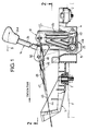
- a lever bracket 1 made of resin is mounted on a floor board of a vehicle through a mount rubber 2.
- the lever bracket 1 is integrally provided with first and second towers 3 and 4 which are juxtaposed in a lateral direction of the vehicle and which commonly includes a partition wall (Figs.2 and 4).
- the first tower 3 is substantially foursquare in section, and is opened at its lower surface.
- the second tower 4 is rectangular which is long in a longitudinal direction of the vehicle and opened at its upper and lower ends.
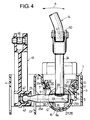
- the first tower 3 is integrally and continuously formed with a housing 5 which is suspended downward from an upper end wall 3a of the first tower 3 along an axis of the tower 3. Opposed peripheral surfaces of the housing 5 and the first tower 3 are connected by a plurality of radial reinforcing ribs 6.
- the housing 5 includes an upper large-diameter cylindrical portion 8 and a lower small-diameter cylindrical portion 9 which are juxtaposed so as to sandwich a step portion 7 provided at an intermediate portion of the housing 5.
- the small-diameter cylindrical portion 9 includes a hemispherical bottom wall 9a.
- the small-diameter cylindrical portion 9 is formed in an inner surface thereof with a guide groove 10 which extended vertically. (see Figs.2 and 4).
- a plurality of engagement holes 11 are formed in the large-diameter cylindrical portion 8 so as to face the step portion 7.
- Vertically slotted holes 12 and 13 are formed in opposed side walls of the small-diameter cylindrical portion 9 and the second tower 4.
- a spherical fulcrum member 15 of the change lever 14 is rotatably engaged with the hemispherical bottom wall 9a of the small-diameter cylindrical portion 9.
- a cap 16 made of resin is relatively rotatably engaged with the fulcrum member 15 from above and is fitted to an inner peripheral surface of the small-diameter cylindrical portion 9.
- a rotation-proof projection 17 (Figs.2 and 5) projected from one side surface of the cap 16 is engaged with the guide groove 10.
- a surface 16a of the cap 16 which is in contact with an outer peripheral surface of the fulcrum member 15 is formed into a spherical surface so as to fit such outer peripheral surface.
- the cap 16 is formed at its outer periphery of the upper end thereof with an annular recess 20 for holding an elastic ring 19 such as an O-ring.
- An annular retainer 21 made of resin for compressing the elastic ring 19 from above so as to press and hold the cap 16 is fitted to inner peripheral surfaces of the large- and small-diameter cylindrical portions 8 and 9.
- a plurality of resilient (eg elastic) engagement claws 22 projected from an outer periphery of the retainer 21 are engaged with the engagement holes 11.
- a tip end of the engagement claw 22 is inclined upward.
- the engagement claw 22 is deflected inward by an inner surface of the large-diameter cylindrical portion 8, and when the engagement claw 22 reaches a position corresponding to the engagement hole 11, the engagement claw 22 engages the engagement hole 11 by its own resilient force.
- the retainer 21 is provided with a step portion 21a which is opposed to the step portion 7 of the housing 5, so that when the retainer 21 is fitted to the housing 5, the compression deformation of the elastic ring 19 by abutment between both the step portions 7 and 21a can be restrained.
- the fulcrum member 15 is rotatably interposed between the cap 16 and the bottom wall 9a of the housing 5 and is subjected to a compressive force applied by the elastic ring 19.
- the change lever 14 includes a bar-like main lever 24 provided at its upper end with a knob 24a, and a bar-like subsidiary lever 25 welded to a lower end of the main lever 24 so as to form a T-shape.
- the subsidiary lever 25 includes long and short rod portions 25a and 25b.
- the long rod portion 25 largely projects from one side of the main lever 24 to pass through the slotted holes 12 and 13 and extends into the second tower 4.
- the short rod portion 25b slightly projects from the other side of the main lever 24.
- the fulcrum member 15 is secured to a junction between the main and the subsidiary levers 24 and 25 so as to cover the junction.
- the fulcrum member 15 is formed into a hollow structure by coupling a pair of cup-like hemispherical bodies 27 and 28 made of resin.
- the hemispherical bodies 27 and 28 have basically symmetrical shapes with respect to a mating surface therebetween.
- Each of the hemispherical bodies 27 and 28 is formed at an end surface thereof with supporting recesses 29, 30 and 31 extending in three directions. These supporting recesses 29, 30 and 31 are fitted to outer peripheries of the main lever 24, as well as the long and short rod portions 25a and 25b of the subsidiary lever 25. At that time, centers of both the hemispherical bodies 27 and 28 are aligned with a junction of axes of the main and subsidiary levers 24 and 25.
- a plurality of positioning holes 33 are formed at the end surface of the hemispherical body 27, and a plurality of positioning projections 32 are formed at the end surface of the hemispherical body 28. By lightly fitting the positioning projections 32 into the positioning holes 33, both the hemispherical bodies 27 and 28 can temporarily be coupled.
- the coupling state between the hemispherical bodies 27 and 28 is reliably retained by sandwiching them between the cap 16 and the bottom wall 9a of the housing 5, as described above.
- Each of the hemispherical bodies 27 and 28 is filled with grease.
- the hemispherical bodies 27 and 28 are formed at their lower mating surfaces and other appropriate portions with grease holes 35 for exuding the grease to the outer periphery of the fulcrum member 15.
- the hemispherical bodies 27 and 28 are also formed at outer peripheries thereof with a lubricant groove 36.
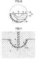
- the hemispherical bodies 27 and 28 are formed at outer peripheries of the end portions thereof with chamfers 34 which are formed during molding. Therefore, when the hemispherical bodies 27 and 28 are formed by a pair of metal dies 37 and 38 as shown in Fig.7, if juncture surfaces of both the metal dies 37 and 38 are brought together with the end surfaces of the hemispherical bodies 27 and 28, it is possible to prevent a burr which protrudes from the produced cavity such as to infiltrate into a clearance between the juncture surfaces of the metal dies 37 and 38, from projecting outward of the outer peripheries of the sperical surface of the hemispherical bodies 27 and 28. Therefore, even if the hemispherical bodies 27 and 28 are assembled into the housing 5 with a burr left as it is, it is possible to prevent the burr from damaging mating members.
- a bell-crank 41 made of resin is mounted to the second tower 4 through a horizontal pivot shaft 40.
- the bell-crank 41 includes a horizontal arm 41a having a swinging end extended forward, and a vertical arm 41b having a swinging end extended upward.
- a bush 43 rotatably mounted to a tip end of the subsidiary lever 25 is slidably fitted to a connection hole 41 formed in the inner surface of the horizontal arm 41a.
- One end of a push-pull select wire 44 is connected to the vertical arm 41b through a rod 46 having a turn buckle 48.
- one end of a push-pull shift wire 45 is connected to a connection piece 50 connected to an intermediate portion of the main lever 24 through a rod 47 having a turnbuckle 49.
- the other ends of the select wire 44 and the shift wire 45 are respectively connected to a select member and a shift member of a transmission (not shown).
- the vertically swingable subsidiary lever 25 drives the horizontal arm 41a of the bell-crank 41 so as to swing the vertical arm 41b in a longitudinal direction of the vehicle. Therefore, a select motion is applied to the transmission through the select wire 44, and a desired gear train is selected. Then, if the operator turns the main lever 24 about the fulcrum member 15 in a shift direction B (in a longitudinal direction of the vehicle), a shift motion is applied to the transmission through the shift wire 45, thereby establishing the previously selected gear train.
- the pair of hemispherical bodies 27 and 28 forming the fulcrum member 15 are formed with three supporting recesses 29, 30 and 31 in which the main and subsidiary levers 24 and 25 intersect each other to form a T-shape. Therefore, it is possible to easily and reliably prevent a relative displacement between the change lever 14 and the fulcrum member 15 in the axial and rotational directions. Therefore, when the change lever 14 is operated, a rotational sliding movement between each contacting surfaces of the housing 5, the cap 16 and the fulcrum member 15 which is lubricated with the grease is smoothly generated.
- the cap 16 and the bottom wall 9a of the housing 5 cooperatively sandwich the fulcrum member 15 with a compressive force, so that frictional wear generated therebetween can automatically be compensated for to prevent backlash from being generated. Further, when the elastic ring 19 is fitted into the housing 5, the elastic ring 19 permits an engagement between the engage claw 22 and the engage hole 11 and holds such engagement state without generating a backlash. Therefore, an attachment member for the retainer 21 becomes unnecessary, which facilitates assembly and simplifies the structure.
- the tip end of the engage claw 22 of the retainer 21 is inclined upward, and the upper surface 11a of the engage hole 11 of the housing 5 is also inclined upward in a radi ally outward direction.Therefore, if the retainer 21 receives an upward load from the side of the cap 16, the engagement claw 22 further strengthens the engagement with the engage hole 11, which reliably prevents the retainer 21 from being disengaged from the housing 5.
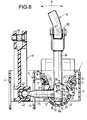
- Fig.8 shows a second embodiment in which the subsidiary lever 25 intersects one side surface of the main lever 24 so as to form a T-shape.
- the hemispherical bodies 27 and 28 are provided at outer peripheral surfaces thereof with a large number of dimples 51 instead of the lubricant groove 36, and each of the hemispherical bodies 27 and 28 is also provided with a grease hole 52 which is opened at a bottom surface of each dimple 51.
- Other structures of the second embodiment are the same as those of the above-described first embodiment.
- portions or components corresponding to those in the first embodiment are designated by like reference characters.
- lubrication around the fulcrum member 15 can be conducted more effectively.
- each of the hemispherical bodies 27 and 28 may be formed into a hollow structure.
Landscapes
- Engineering & Computer Science (AREA)
- General Engineering & Computer Science (AREA)
- Mechanical Engineering (AREA)
- Arrangement Or Mounting Of Control Devices For Change-Speed Gearing (AREA)
- Control Of Transmission Device (AREA)
- Pivots And Pivotal Connections (AREA)
Applications Claiming Priority (2)
| Application Number | Priority Date | Filing Date | Title |
|---|---|---|---|
| JP7001368A JPH08189557A (ja) | 1995-01-09 | 1995-01-09 | チェンジレバーの支持構造 |
| JP1368/95 | 1995-01-09 |
Publications (2)
| Publication Number | Publication Date |
|---|---|
| EP0721073A2 true EP0721073A2 (fr) | 1996-07-10 |
| EP0721073A3 EP0721073A3 (fr) | 1997-10-08 |
Family
ID=11499560
Family Applications (1)
| Application Number | Title | Priority Date | Filing Date |
|---|---|---|---|
| EP95303802A Withdrawn EP0721073A3 (fr) | 1995-01-09 | 1995-06-05 | Elément de support pour levier de changement de vitesse |
Country Status (3)
| Country | Link |
|---|---|
| US (1) | US5560252A (fr) |
| EP (1) | EP0721073A3 (fr) |
| JP (1) | JPH08189557A (fr) |
Cited By (1)
| Publication number | Priority date | Publication date | Assignee | Title |
|---|---|---|---|---|
| US11486491B2 (en) * | 2019-07-11 | 2022-11-01 | Toyota Jidosha Kabushiki Kaisha | Shift device for vehicle that includes a shift lever and a control lever that are separately supported by a baseplate |
Families Citing this family (7)
| Publication number | Priority date | Publication date | Assignee | Title |
|---|---|---|---|---|
| US5791197A (en) * | 1996-07-24 | 1998-08-11 | Grand Haven Stamped Products | Automatic transmission shifter with manual shift mode |
| US6067873A (en) * | 1998-09-18 | 2000-05-30 | Grand Haven Stamped Prod | Shifter with novel mounting arrangement |
| US20030213326A1 (en) * | 2002-05-14 | 2003-11-20 | Fett Brian W. | Cable-operated transmission shifters |
| US7971502B2 (en) * | 2006-10-25 | 2011-07-05 | Nexteer (Beijing) Technology, Co., Ltd. | Assembly with metal casting and polymeric member and transmission shift mechanism including same |
| DE102010021559A1 (de) * | 2010-05-26 | 2011-12-01 | Gm Global Technology Operations Llc (N.D.Ges.D. Staates Delaware) | Gangschalthebel mit Dämpfungsvorrichtung eines Fahrzeugs |
| DE102010021961A1 (de) * | 2010-05-28 | 2012-04-19 | Bomag Gmbh | Schwingungserreger für ein Bodenverdichtungsgerät und Bodenverdichtungsgerät |
| JP2014004974A (ja) * | 2012-06-27 | 2014-01-16 | Fuji Kiko Co Ltd | シフトレバー装置 |
Citations (1)
| Publication number | Priority date | Publication date | Assignee | Title |
|---|---|---|---|---|
| JPH02229950A (ja) | 1987-09-21 | 1990-09-12 | Toyota Motor Corp | 変速機のシフトレバー支持装置 |
Family Cites Families (6)
| Publication number | Priority date | Publication date | Assignee | Title |
|---|---|---|---|---|
| US3547474A (en) * | 1969-07-15 | 1970-12-15 | Trw Inc | Boot seal |
| JPS5125902B2 (fr) * | 1972-01-28 | 1976-08-03 | ||
| DE8437043U1 (de) * | 1984-12-18 | 1985-04-11 | Fhs Stahlverformung Gmbh, 5860 Iserlohn | Lagergehaeuse fuer kraftfahrzeug-gangschalthebel mit rueckwaertsgangsperre |
| US4873884A (en) * | 1987-09-08 | 1989-10-17 | Toyota Jidosha Kabushi Kaisha | Apparatus for supporting shift lever for transmission |
| DE8913506U1 (de) * | 1989-11-15 | 1990-02-15 | Fritz Himmermann Gmbh & Co Kg, 53940 Hellenthal | Kunststoffgleitlager |
| DE4127730A1 (de) * | 1991-08-22 | 1993-03-04 | Ford Werke Ag | Schalthebellagerung fuer getriebe von kraftfahrzeugen |
-
1995
- 1995-01-09 JP JP7001368A patent/JPH08189557A/ja active Pending
- 1995-06-01 US US08/456,322 patent/US5560252A/en not_active Expired - Lifetime
- 1995-06-05 EP EP95303802A patent/EP0721073A3/fr not_active Withdrawn
Patent Citations (1)
| Publication number | Priority date | Publication date | Assignee | Title |
|---|---|---|---|---|
| JPH02229950A (ja) | 1987-09-21 | 1990-09-12 | Toyota Motor Corp | 変速機のシフトレバー支持装置 |
Cited By (1)
| Publication number | Priority date | Publication date | Assignee | Title |
|---|---|---|---|---|
| US11486491B2 (en) * | 2019-07-11 | 2022-11-01 | Toyota Jidosha Kabushiki Kaisha | Shift device for vehicle that includes a shift lever and a control lever that are separately supported by a baseplate |
Also Published As
| Publication number | Publication date |
|---|---|
| EP0721073A3 (fr) | 1997-10-08 |
| US5560252A (en) | 1996-10-01 |
| JPH08189557A (ja) | 1996-07-23 |
Similar Documents
| Publication | Publication Date | Title |
|---|---|---|
| EP0719965B1 (fr) | Elément de support pour levier de changement de vitesse | |
| JPS6336421Y2 (fr) | ||
| JPH0712621U (ja) | ボールジョイント | |
| US5092017A (en) | Automotive door hinge assembly, bush employed therein and method for installing bush in door hinge assembly | |
| US4873884A (en) | Apparatus for supporting shift lever for transmission | |
| US4879922A (en) | Operating device for transmission | |
| US5497673A (en) | Automatic transmission operating device | |
| US6237435B1 (en) | Control device | |
| US4795288A (en) | Yoke member connecting device in windshield wiper | |
| CA2175304C (fr) | Element de transmission du mouvement d'un dispositif de telecommande | |
| JPH07259842A (ja) | ボール接手 | |
| EP0721073A2 (fr) | Elément de support pour levier de changement de vitesse | |
| EP0978669A2 (fr) | Dispositif de commande à deux modes pour transmission automatique | |
| US5896778A (en) | Operating lever device for manual transmissions for motor vehicles | |
| EP0747612B1 (fr) | Dispositif de changement de vitesse pour transmission | |
| US5367913A (en) | Pinion shift device for starter and assembly method of the same | |
| US4077275A (en) | Gearshift lever assembly | |
| US7159486B2 (en) | Joint arrangement for a gear shift mechanism | |
| JPH08189558A (ja) | チェンジ装置の潤滑構造 | |
| JP3214793B2 (ja) | チェンジレバーの支持構造 | |
| JPH106801A (ja) | 自動車におけるチェンジレバー用取付基板の弾性支持装置 | |
| KR100309330B1 (ko) | 자동차 변속기의 시프트레버 지지장치 | |
| JP2603732Y2 (ja) | 防振ブッシュ | |
| JPH0237621Y2 (fr) | ||
| EP0376902A1 (fr) | Unité de commande d'une boîte de vitesse pour véhicules utilitaires |
Legal Events
| Date | Code | Title | Description |
|---|---|---|---|
| PUAI | Public reference made under article 153(3) epc to a published international application that has entered the european phase |
Free format text: ORIGINAL CODE: 0009012 |
|
| AK | Designated contracting states |
Kind code of ref document: A2 Designated state(s): DE FR GB IT |
|
| PUAL | Search report despatched |
Free format text: ORIGINAL CODE: 0009013 |
|
| AK | Designated contracting states |
Kind code of ref document: A3 Designated state(s): DE FR GB IT |
|
| 17P | Request for examination filed |
Effective date: 19971030 |
|
| 17Q | First examination report despatched |
Effective date: 19981216 |
|
| STAA | Information on the status of an ep patent application or granted ep patent |
Free format text: STATUS: THE APPLICATION IS DEEMED TO BE WITHDRAWN |
|
| 18D | Application deemed to be withdrawn |
Effective date: 19990427 |