EP0721149B1 - Verfahren zur Übertragung der Szenenorientierung eines Kamerafilmes zu einem Fotobehandlungsgerät - Google Patents
Verfahren zur Übertragung der Szenenorientierung eines Kamerafilmes zu einem Fotobehandlungsgerät Download PDFInfo
- Publication number
- EP0721149B1 EP0721149B1 EP96200029A EP96200029A EP0721149B1 EP 0721149 B1 EP0721149 B1 EP 0721149B1 EP 96200029 A EP96200029 A EP 96200029A EP 96200029 A EP96200029 A EP 96200029A EP 0721149 B1 EP0721149 B1 EP 0721149B1
- Authority
- EP
- European Patent Office
- Prior art keywords
- film
- strip
- splicing
- label
- scene orientation
- Prior art date
- Legal status (The legal status is an assumption and is not a legal conclusion. Google has not performed a legal analysis and makes no representation as to the accuracy of the status listed.)
- Expired - Lifetime
Links
- 238000000034 method Methods 0.000 title claims description 20
- 238000003384 imaging method Methods 0.000 claims description 12
- 230000003287 optical effect Effects 0.000 description 4
- 238000001514 detection method Methods 0.000 description 3
- 239000000839 emulsion Substances 0.000 description 3
- 238000004519 manufacturing process Methods 0.000 description 3
- 239000000853 adhesive Substances 0.000 description 2
- 230000001070 adhesive effect Effects 0.000 description 2
- 238000010586 diagram Methods 0.000 description 2
- 230000000007 visual effect Effects 0.000 description 2
- 230000001419 dependent effect Effects 0.000 description 1
- 239000011159 matrix material Substances 0.000 description 1
- 238000012986 modification Methods 0.000 description 1
- 230000004048 modification Effects 0.000 description 1
Images
Classifications
-
- G—PHYSICS
- G03—PHOTOGRAPHY; CINEMATOGRAPHY; ANALOGOUS TECHNIQUES USING WAVES OTHER THAN OPTICAL WAVES; ELECTROGRAPHY; HOLOGRAPHY
- G03D—APPARATUS FOR PROCESSING EXPOSED PHOTOGRAPHIC MATERIALS; ACCESSORIES THEREFOR
- G03D15/00—Apparatus for treating processed material
- G03D15/04—Cutting; Splicing
-
- G—PHYSICS
- G03—PHOTOGRAPHY; CINEMATOGRAPHY; ANALOGOUS TECHNIQUES USING WAVES OTHER THAN OPTICAL WAVES; ELECTROGRAPHY; HOLOGRAPHY
- G03B—APPARATUS OR ARRANGEMENTS FOR TAKING PHOTOGRAPHS OR FOR PROJECTING OR VIEWING THEM; APPARATUS OR ARRANGEMENTS EMPLOYING ANALOGOUS TECHNIQUES USING WAVES OTHER THAN OPTICAL WAVES; ACCESSORIES THEREFOR
- G03B27/00—Photographic printing apparatus
- G03B27/32—Projection printing apparatus, e.g. enlarger, copying camera
-
- G—PHYSICS
- G03—PHOTOGRAPHY; CINEMATOGRAPHY; ANALOGOUS TECHNIQUES USING WAVES OTHER THAN OPTICAL WAVES; ELECTROGRAPHY; HOLOGRAPHY
- G03B—APPARATUS OR ARRANGEMENTS FOR TAKING PHOTOGRAPHS OR FOR PROJECTING OR VIEWING THEM; APPARATUS OR ARRANGEMENTS EMPLOYING ANALOGOUS TECHNIQUES USING WAVES OTHER THAN OPTICAL WAVES; ACCESSORIES THEREFOR
- G03B31/00—Associated working of cameras or projectors with sound-recording or sound-reproducing means
- G03B31/06—Associated working of cameras or projectors with sound-recording or sound-reproducing means in which sound track is associated with successively-shown still pictures
-
- G—PHYSICS
- G03—PHOTOGRAPHY; CINEMATOGRAPHY; ANALOGOUS TECHNIQUES USING WAVES OTHER THAN OPTICAL WAVES; ELECTROGRAPHY; HOLOGRAPHY
- G03D—APPARATUS FOR PROCESSING EXPOSED PHOTOGRAPHIC MATERIALS; ACCESSORIES THEREFOR
- G03D15/00—Apparatus for treating processed material
-
- G—PHYSICS
- G03—PHOTOGRAPHY; CINEMATOGRAPHY; ANALOGOUS TECHNIQUES USING WAVES OTHER THAN OPTICAL WAVES; ELECTROGRAPHY; HOLOGRAPHY
- G03D—APPARATUS FOR PROCESSING EXPOSED PHOTOGRAPHIC MATERIALS; ACCESSORIES THEREFOR
- G03D15/00—Apparatus for treating processed material
- G03D15/001—Counting; Classifying; Marking
- G03D15/003—Marking, e.g. for re-printing
-
- G—PHYSICS
- G03—PHOTOGRAPHY; CINEMATOGRAPHY; ANALOGOUS TECHNIQUES USING WAVES OTHER THAN OPTICAL WAVES; ELECTROGRAPHY; HOLOGRAPHY
- G03B—APPARATUS OR ARRANGEMENTS FOR TAKING PHOTOGRAPHS OR FOR PROJECTING OR VIEWING THEM; APPARATUS OR ARRANGEMENTS EMPLOYING ANALOGOUS TECHNIQUES USING WAVES OTHER THAN OPTICAL WAVES; ACCESSORIES THEREFOR
- G03B2206/00—Systems for exchange of information between different pieces of apparatus, e.g. for exchanging trimming information, for photo finishing
- G03B2206/004—Systems for exchange of information between different pieces of apparatus, e.g. for exchanging trimming information, for photo finishing using markings on the photographic material, e.g. to indicate pseudo-panoramic exposure
- G03B2206/006—Systems for exchange of information between different pieces of apparatus, e.g. for exchanging trimming information, for photo finishing using markings on the photographic material, e.g. to indicate pseudo-panoramic exposure of the bar-code type
Definitions
- This invention relates generally to the field of image processing, and more particularly to a method for communicating the scene orientation of an exposed strip of photographic film to photo finishing equipment with a film-splicing label having label encoded information imprinted thereon for identifying film used in right hand or left hand load cameras, and to a film-splicing label encoded with indicia for identifying the scene orientation.
- a film magazine When film is exposed in a conventional camera it is normally advanced from left to right.
- a film magazine can be loaded on the left hand side and wound in the normal wind direction, i.e. the first or lowest numbered frame is exposed first and the film is returned back into the magazine, after all the pictures are taken, or it can be wound in the reverse wind direction, in which the film is first extracted out of the magazine and returned to the magazine as each picture is taken, i.e. the first frame on which a picture is taken is the first frame wound onto the magazine and corresponds to the highest numbered frame.
- the film magazine may also be loaded on the right hand side of a camera and either normal wind or reverse wind film transport techniques may be used.
- Cameras which utilize right hand load and a reverse wind technique include the increasingly popular single use cameras (SUC's) where it is more economical and reliable to put the magazine on the right side and thus eliminate the rewinding mechanism.
- SUC's single use cameras
- a right hand load camera causes the scene on the film to be inverted when it is printed by an optical printer because, by convention, the printer receives the lowest numbered end of the film first and prints from the lowest frame number on the film to the highest frame number.
- the printer has no way to detect if the scene is an inverted or normal scene.
- the knowledge of the image orientation of a scene has application for conventional optical printing since this information is critical to the exposure determining algorithms in the printer software.
- Automatic digital imaging applications such as the production of compact discs containing photographic images, and index prints on such discs, digitally printed automatic album pages, etc., also require that the images be correctly oriented before the final output image format is generated.
- the scene inversion information is normally manually inputted to the printer setup values and remains fixed until the operator changes it. If this value is set to the normal scene orientation setting, then all film is treated in like manner, even if it is right hand load.
- US-A-4 659 213 discloses a method and apparatus for detecting image information which has been recorded on the marginal portion of a film negative sheet outside of the film image.
- the marginal information such as bar codes, may be used during photographic printing so as to discriminate the front surface from the back surface and/or to discriminate the top edge of the film from the bottom edge. If the negative film is mounted in an inverse direction, the printing exposure amount and correction may be determined.
- SUC's use normal film which can be readily identified as right hand load and sorted manually. There is a need for a way in which normal film, exposed in either left or right hand load cameras, can be encoded as to orientation and processed in existing photo finishing equipment at high speed and therefore at low cost.
- US-A-4 800 406 discloses a method and apparatus for creating and checking correlation between negatives and prints in photographic laboratories by joining adjacent pairs of filmstrips with splicing tapes bearing machine-readable control numbers that are unrelated to orientation and reproducing each of said numbers onto the print medium at the printing station.
- US-A-5 248 887 discloses a method and apparatus for determining the orientation of film by providing the strip of exposed film with a timing track along one of the longitudinal margins thereof.
- the track includes a sequence of three segments.
- a sensor detects the position arid width of the segments to determine the orientation of the film and thus distinguishes that the emulsion side is correctly oriented and whether the first or last exposure was inserted as the leading end.
- suitable printers an incorrectly oriented film can be detected and inverted electronically so that the image can be printed with the correct orientation.
- imaging is used as a blanket term for techniques used to convert an image on a film into a format for viewing, such as optical printing or digital scanning for printing, video displaying or projecting
- imaging parameters is used as a blanket term for those variables which can be set for photofinishing equipment, in order to produce a viewable image, such as scene orientation, subject classification, exposure determination and color, density and contrast determinations.
- a label suitable for use in splicing one strip of photographic film is provided as defined in claim 3.
- this invention provides improved image quality by knowing the scene orientation.
- the invention is disclosed as being embodied preferably in encoding film loaded in a magazine (cassette) for use with a 35mm still camera. Because such a film and camera are well known, this description is directed in particular to photographic elements forming part of or cooperating directly with the disclosed embodiment.
- the encoding method is described for use with single use cameras with the normal 35mm format. However, such cameras using panoramic or telephoto formats and waterproof camera versions and cameras using other film sizes also fall within the invention.
- the film is advanced from left to right in the conventional manner. It is to be understood however, that the encoding method is readily adaptable for cameras in which the film is advanced from right to left, and that other elements not specifically shown or described may take various forms known to persons of ordinary skill in the art.
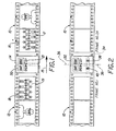
- an exposed strip of a first film 10 is shown spliced to an exposed strip of a second film 12, a right hand load film, by means of a film-splicing label 14. Both films are viewed with the emulsion side up and the splicing label 14 is mounted on the emulsion side of the films.
- the spliced films are fed to photo finishing equipment, for example a printer, in the direction of the arrow 15.
- the trailing end of film 10 has the highest number frame 16, for example exposure 24 of a 24-exposure 35mm film, shown with normal scene orientation of the image 17.
- This trailing end is spliced to the leading end of film 12 which shows the lowest numbered frame 18, for example exposure 1 of a 24-exposure 35 mm film, with inverted scene orientation of the image 19.
- the splicing label is adhesively attached to the ends of the film to join them together by means of an automatic splicing machine, for example, the Ultima Day Light Splicer manufactured by Standard Manufacturing of Chicopee, MA.
- a tape of film-splicing labels, coated with heat activated adhesive on one side, is fed to a splicer where contact is made with adjacent rolls of film under the splice head. Pressure and heat is used to adhesively attach the label to the adjacent rolls of film.
- the temperature of the splice head is preferably about 177°C (350°F).
- the adhesive is compatible with subsequent developing and imaging operations.
- Such labels are usually provided with a preprinted machine readable and/or eye readable code, for example, a sequential bar code 20 or an eye readable number 21. Such codes can be used to automatically correlate the film with the customers envelope number so that the processed film and prints can be matched after printing is completed.
- the spliced together film strips then go to a film developer which develops the exposed frames.
- the developed films are then supplied to the appropriate imaging equipment, for example, a printer.
- the film-splicing label 14 can be further encoded and used to identify the film 12 as a right hand load film by any suitable means which can signal a compatible printer with the information and activate the parameters, such as the exposure determining algorithms in the printer software, to expose for an inverted image.
- the label can be encoded for left hand load film if the next succeeding film in a roll of spliced films is left hand load and thus signal to the printer for a normal image.
- Any machine-readable or optical-readable coding system can be used which is compatible with the equipment used for splicing, developing and printing.
- the film-splicing label can also be encoded and used to signal automatic digital imaging equipment to activate the parameters for the correct scene orientation.
- the scene orientation code is added to the film-splicing label immediately following the splicing step.
- Printing high resolution indicia, such as bar codes or number sequences, on the film-splicing label in the splicer would require expensive printing and scanning equipment to provide the printing quality and reading capability needed for reliably reading the code at the high through put speeds encountered during the splicing operation.
- a low resolution, robust encoding method requiring inexpensive printing and reading equipment for providing high speed printing and reliably reading the code is provided by modifying known automatic print count code (APC) systems to automatically signal the scene orientation of an exposed filmstrip to imaging equipment.
- API automatic print count code
- One such system for 35mm color film is the Kodak Splice Print Count Reader which is installed on a Kodak 2610 Color Printer or Kodak 3510 Color Printer (all manufactured by Eastman Kodak Company, Rochester, N.Y.) and used in conjunction with the Ultima Day Light Splicer.
- This system requires that the printer be set for first-frame-first operation.
- This system performs the function of adjusting the number of prints per frame exposed by the printer, for a particular customer order. This eliminates the need for the photo finisher to segregate his 1-, 2-, 3-, and 4-each orders and multi-print orders can flow through with normal orders.
- the APC code is under-utilized because most people require only 1 or 2 prints, not 3 or 4 prints. It is an object of this invention to utilize the APC code to indicate normal or inverted scene orientation by modifying the code and setting the parameters to encode for orientation and/or print count.
- the film-splicing label for use with this invention is provided with an area reserved for adding an APC code in the splicer which is normally used to signal to a printer the number of prints of each frame which are required for the succeeding strip of film.
- Such a label can also carry additional preprinted codes as described above.
- FIG. 2 there is shown a preferred method of coding for scene orientation in which a film-splicing label 32 joins a first film 10 and a second film 12 together.
- the APC code is located on a nominal print area 34 of the label and is automatically centered on the mid-point 36 between the last frame of the first film and the first frame of the second film and is utilized to encode for the scene orientation of the second film.
- Such films are usually contained in a large multi-film roll of spliced films which can be continuously and rapidly fed to an automatic printer.
- the printer senses the code for each label and activates the algorithms in the printer software for the selected scene orientation.
- the APC code is an operator selected binary, two dot code placed on the film-splicing label when the splice is made. It consists of the area 34 which can be scanned for the presence or absence of a pattern of relatively large, low resolution indicia, for example, dark dots or rectangular patches. The specific locations for the dots are established by convention and are made at, for example, locations 38, 40 on either side of and equidistant from the mid-point of the film-splicing label.
- Such low resolution indicia have a minimum size for detection by a reader and a maximum for fitting in the allotted area of the splicing label, for example, between about 1.25mm 2 (0.05in 2 ) and about 9.5mm 2 (0.375in 2 ).
- the code is imprinted on the film-splicing label by a printer such as an impact printer, for example a dot matrix printer, which can imprint a dark dot or rectangular patch of sufficient density and dimensions as required for sensing by an optical reader.
- a printer such as an impact printer, for example a dot matrix printer, which can imprint a dark dot or rectangular patch of sufficient density and dimensions as required for sensing by an optical reader.
- Such a reader is installed in the Kodak Splice Print Count Reader and requires the difference in visual density between the indicia and splice tape to equal or exceed 0.5 on a visual scale.
- the labels are provided in the form of a splice tape of a standard width, for example, 13mm (0.5in), 19mm (0.75in) or 25mm (lin).
- a 25mm (lin) wide label the area 34 measures, for example, 20mm (0.8in) wide by 2.3mm (0.09in) high and each rectangular patch measures 2.5mm (0.1in) wide by 2.3mm (0.09in) high.
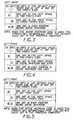
- Figures 3, 4 and 5 illustrate three of several different patterns that can be used for the scene inversion code together with the print count requirement.
- the absence of any dots is the default value which can be set so that the print count is one or two prints each.
- One dot in each position sets the printer for scene inversion. By setting the default value to one print each the scene inversion code will automatically print one print each. By setting the default value to two prints each the scene inversion code will automatically print two prints each. In this version of the code, one dot on the left space will print two prints each for normal scene orientation, one dot in the right space will print three prints each for normal scene orientation and depending on the setting of the default value, no dots will print one or two prints for normal scene orientation.
- the absence of any dots is the default value which can be set so that the print count is one or two prints each.
- One dot in each position sets the printer for scene inversion. By setting the default value to one print each the scene inversion code will automatically print one print each. By setting the default value to two prints each the scene inversion code will automatically print two prints each. In this version of the code, one dot on the left space will print one print each for normal scene orientation, one dot in the right space will print three prints each for normal scene orientation and depending on the setting of the default value, no dots will print one or two prints for normal scene orientation.
- the invention is not limited to these patterns of dots as various other patterns can be envisaged by those skilled in the field and used for specific demands.
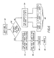
- FIG. 6 a block diagram of a typical control system (logic flowchart) for sorting of films for scene inversion detection is shown.
- Film magazines from 35mm left hand load cameras and 35mm right hand load SUC cameras are collected in carts 50 and presorted into separate carts or bins 52 for each type of film.
- SUC films requiring scene inversion are selected and sent to a film opener/splicer 54 where each film is extracted and spliced to another film by adhesively attaching a film-splicing label adjacent to the first numbered frame of the SUC film and the last numbered frame of the other film.
- the label is then encoded with the APC code for scene inversion and prints per negative by a printer according to the designated pattern 56 (see Figures 3, 4 and 5).
- the roll of spliced films formed by splicing successive films is fed to a printer/reader 58 which senses the APC code, activates the algorithms in the printer software for scene inversion and prints the selected number of prints 60.
- Non-SUC or normal left hand load films are selected and sent to the film/opener splicer 54 where each film is extracted and spliced to another film by adhesively attaching a film-splicing label adjacent to the first numbered frame of the normal film and the last numbered frame of the other film.
- the label is then encoded with the APC code for the selected number of prints to be printed 62, for example 1, 2 or 3 prints, with normal scene orientation.
- This invention can also be used for other types of photo finishing equipment, for example, automatic digital imaging applications, such as the production of compact discs containing photographic images, and index prints on such discs, digitally or conventionally printed automatic album pages, etc., which also require that the images be correctly oriented before the final output image format is generated. It is envisaged also that this invention can be used with non-magazine loaded types of film.
- This invention provides an advantageous method for a photo finisher to control and provide optimal print exposure parameters for the correct scene orientation. This is achieved by encoding a film-splicing label with an APC code pattern selected to indicate whether successive lengths of spliced film have normal or inverted scene orientation.
- APC code pattern selected to indicate whether successive lengths of spliced film have normal or inverted scene orientation.
- Existing photo finishing equipment can be readily adapted to use this method and increased print quality and productivity is achieved. As SUC's become more prevalent in the market place, indication of the film scene orientation becomes more valuable.
Landscapes
- Physics & Mathematics (AREA)
- General Physics & Mathematics (AREA)
- Projection-Type Copiers In General (AREA)
- Photographic Processing Devices Using Wet Methods (AREA)
Claims (4)
- Verfahren zum Übermitteln der Szenenorientierung eines auf der linken oder rechten Seite einer fotografischen Kamera eingelegten, belichteten Filmstreifens an ein Entwicklungslaborgerät zur automatischen Einstellung von Bilderzeugungsparametern in diesem Gerät, wobei das Verfahren folgende Schritte aufweist:Zusammenkleben durch Wärme und Druck des Endes eines ersten belichteten Filmstreifens (10) mit dem Anfang eines zweiten belichteten Filmstreifens (12) mittels eines Klebestreifens (32); undKodieren des Klebestreifens (32) mit einem Code als Identifizierungsmerkmal (20, 21), das mit relativ hoher Auflösung aufgedruckt ist, und Informationen zur Identifizierung und Unterscheidung des zweiten belichteten Filmstreifens von anderen Filmstreifen in einer Charge von Streifen liefert, und mit einem zweiten, maschinenlesbaren Identifizierungsmerkmal (38, 40), das mit niedrigerer Auflösung an einer vorbestimmten Stelle aufgedruckt ist, und Informationen liefert, welche die Einlegung des zweiten Films auf der linken oder rechten Seite der fotografischen Kamera identifiziert.
- Verfahren nach Anspruch 1, gekennzeichnet durch folgenden Schritt:Zuführen des angeklebten, zweiten Filmstreifens einem Lesegerät für Filmklebestreifen, das den Code liest und automatisch die Parameter für umgekehrte Szenenorientierung einstellt.
- Klebestreifen (32) zur Verwendung beim Zusammenkleben eines fotografischen Filmstreifens (10) mit aufbelichteten Bildern in einer von einer ersten Szenenorientierung und einer zweiten Szenenorientierung, die einer Einlegung des belichteten Filmstreifens auf der linken oder rechten Seite einer fotografischen Kamera entspricht, mit einem weiteren fotografischen Filmstreifen (12) zur Chargenentwicklung und Bildherstellung, wobei der Klebestreifen folgende Komponenten aufweist:eine erste Fläche zum Aufkleben des Klebestreifens (32) auf die Filmstreifen (10, 12); undeine zweite Fläche (34) mit einem Code als Identifizierungsmerkmal (20, 21), das mit relativ hoher Auflösung aufgedruckt ist, und Informationen zur Identifizierung und Unterscheidung des zusammengeklebten Filmstreifens in einer Charge von anderen Filmstreifen in der Charge liefert, und mit einem zweiten, maschinenlesbaren Identifizierungsmerkmal (38, 40), das mit niedrigerer Auflösung aufgedruckt ist, und Informationen liefert, die in einem Laborentwicklungsgerät für die Identifizierung der Szenenorientierung auf dem Filmstreifen verwendbar sind.
- Verfahren nach Anspruch 1, gekennzeichnet durch folgende Schritte:Bereitstellen eines Filmklebestreifens (32) mit einem darauf vorgedruckten Identifizierungsmerkmal (20, 21) mit hoher Auflösung zur eindeutigen Identifizierung eines Filmstreifens;Identifizieren der Szenenorientierung des Films; undAufbringen eines zweiten Identifizierungsmerkmals (38, 40) mit niedriger Auflösung auf dem Filmklebestreifen, das die Szenenorientierung des Filmstreifens identifiziert.
Applications Claiming Priority (2)
| Application Number | Priority Date | Filing Date | Title |
|---|---|---|---|
| US08/369,942 US5530517A (en) | 1995-01-09 | 1995-01-09 | Method for communicating scene orientation of camera film to photo finishing equipment |
| US369942 | 1995-01-09 |
Publications (2)
| Publication Number | Publication Date |
|---|---|
| EP0721149A1 EP0721149A1 (de) | 1996-07-10 |
| EP0721149B1 true EP0721149B1 (de) | 2002-05-08 |
Family
ID=23457574
Family Applications (1)
| Application Number | Title | Priority Date | Filing Date |
|---|---|---|---|
| EP96200029A Expired - Lifetime EP0721149B1 (de) | 1995-01-09 | 1996-01-05 | Verfahren zur Übertragung der Szenenorientierung eines Kamerafilmes zu einem Fotobehandlungsgerät |
Country Status (5)
| Country | Link |
|---|---|
| US (2) | US5530517A (de) |
| EP (1) | EP0721149B1 (de) |
| JP (1) | JPH08240900A (de) |
| KR (1) | KR960029881A (de) |
| DE (1) | DE69621056T2 (de) |
Families Citing this family (27)
| Publication number | Priority date | Publication date | Assignee | Title |
|---|---|---|---|---|
| JP2970454B2 (ja) * | 1995-01-30 | 1999-11-02 | ノーリツ鋼機株式会社 | 写真焼付装置 |
| JPH0944592A (ja) * | 1995-05-23 | 1997-02-14 | Olympus Optical Co Ltd | 情報再生システム |
| JPH0981711A (ja) * | 1995-09-20 | 1997-03-28 | Olympus Optical Co Ltd | 情報記録媒体、情報再生システム、及び情報記録システム |
| US5905580A (en) * | 1995-11-09 | 1999-05-18 | Eastman Kodak Company | System and article of manufacture for producing an index print from photographic negative strips |
| US5748289A (en) * | 1996-08-29 | 1998-05-05 | Eastman Kodak Company | Apparatus and method for producing photographic prints with write-on borders |
| US6050489A (en) * | 1997-04-08 | 2000-04-18 | Fuji Photo Film Co., Ltd. | Bar code system for brownie film and bar code reader of camera |
| US5973734A (en) | 1997-07-09 | 1999-10-26 | Flashpoint Technology, Inc. | Method and apparatus for correcting aspect ratio in a camera graphical user interface |
| US6021942A (en) * | 1997-12-12 | 2000-02-08 | Moore U.S.A. Inc. | Bar-coded label for "attempt to deliver" parcels |
| US6101000A (en) * | 1998-01-30 | 2000-08-08 | Eastman Kodak Company | Photographic processing apparatus and method |
| US6181409B1 (en) | 1998-02-13 | 2001-01-30 | Eastman Kodak Company | System for backprinting photographic media |
| NL1010093C2 (nl) * | 1998-09-15 | 2000-03-17 | Techn O Tape B V | Tape voor het verbinden van te ontwikkelen fotografische films en werkwijze voor de vervaardiging ervan. |
| US6317141B1 (en) | 1998-12-31 | 2001-11-13 | Flashpoint Technology, Inc. | Method and apparatus for editing heterogeneous media objects in a digital imaging device |
| EP1137247A3 (de) * | 2000-01-28 | 2002-10-09 | Eastman Kodak Company | Digitales Fotobehandlungssystem |
| US6366738B1 (en) | 2000-02-21 | 2002-04-02 | Eastman Kodak Company | Camera with print quantity designation for each exposure provides print cost total |
| US6761677B1 (en) * | 2000-09-22 | 2004-07-13 | Eastman Kodak Company | Album leaf and method and apparatus for making an album leaf |
| US6628895B2 (en) | 2001-02-16 | 2003-09-30 | Eastman Kodak Company | Apparatus and method for obtaining special images from a one time use camera |
| USD510377S1 (en) * | 2002-06-22 | 2005-10-04 | Jack Roe (Cs) Limited | Fragmentary portion of cinematographic film |
| US7279209B2 (en) * | 2003-12-05 | 2007-10-09 | Ricoh Electronics, Inc. | Runnable splice |
| US20060002690A1 (en) * | 2004-07-01 | 2006-01-05 | Eastman Kodak Company | Intelligent media splice |
| US9224145B1 (en) | 2006-08-30 | 2015-12-29 | Qurio Holdings, Inc. | Venue based digital rights using capture device with digital watermarking capability |
| US8199999B2 (en) * | 2008-06-17 | 2012-06-12 | Cambridge Research & Instrumentation, Inc. | Image classifier training |
| US8967482B2 (en) * | 2011-05-23 | 2015-03-03 | Intellectual Ventures Fund 83 Llc | Image selection method using machine-readable codes |
| US20130026223A1 (en) * | 2011-07-28 | 2013-01-31 | Thomas Joseph Murray | Selecting images using machine-readable codes |
| FR2986992B1 (fr) * | 2012-02-21 | 2015-06-26 | Cristian Todie | Procede de creation de motifs et de reliefs sur les piles, sur les parties alveolaires et sur les tranches d'objets en feuilles |
| JP6045037B2 (ja) * | 2014-03-03 | 2016-12-14 | 大成ラミック株式会社 | 充填包装機用積層フィルムのフィルム繋ぎ部分の検出方法 |
| US12014093B2 (en) | 2022-10-05 | 2024-06-18 | Xerox Corporation | Communication architecture promoting compatibility with printing finishing equipment |
| CN116976122B (zh) * | 2023-08-02 | 2024-02-27 | 虎丘影像(苏州)股份有限公司 | 一种打印机供热装置设计方法 |
Family Cites Families (21)
| Publication number | Priority date | Publication date | Assignee | Title |
|---|---|---|---|---|
| DE2749721C2 (de) * | 1977-11-07 | 1984-12-06 | Agfa-Gevaert Ag, 5090 Leverkusen | Verfahren und Vorrichtung zur Berücksichtigung der Eigenheiten der verschiedenen Filmsorten beim Farbkopieren |
| US4541028A (en) * | 1981-12-04 | 1985-09-10 | Johnson Reynold B | Hand-held transducing device for insertable records |
| EP0136980B1 (de) * | 1983-10-05 | 1987-09-02 | GRETAG Aktiengesellschaft | Verfahren und Vorrichtung zur Herstellung von fotografischen Kopien |
| US4659213A (en) * | 1985-04-08 | 1987-04-21 | Fuji Photo Film Co., Ltd. | Method and apparatus for detecting and processing image information |
| IT1187459B (it) * | 1985-11-11 | 1987-12-23 | Photo Eng Int | Procedimento per creare e verificare la correlazione tra negativi e stampe in laboratori fotografici ed apparecchiatura per attuare il procedimento |
| JP2630769B2 (ja) * | 1987-01-19 | 1997-07-16 | 株式会社トリオ電子 | 録音再生装置を備えたカード及びメール |
| US4821061A (en) * | 1987-02-20 | 1989-04-11 | Standard Manufacturing | Photofinishing packaging system |
| US5045327A (en) * | 1987-06-24 | 1991-09-03 | Sound Memory Corporation | Digital recording and playback module system |
| JPH01282535A (ja) * | 1988-05-09 | 1989-11-14 | Canon Inc | 撮影フイルムのプリント装置 |
| US5032707A (en) * | 1989-02-08 | 1991-07-16 | Standard Manufacturing | Bagless film handling system |
| US5128700A (en) * | 1989-05-12 | 1992-07-07 | Minolta Camera Kabushiki Kaisha | Camera capable of recording sounds relevant to the photographing |
| US5241166A (en) * | 1990-07-02 | 1993-08-31 | Chandler Donald G | Low resolution target acquisition |
| US5159385A (en) * | 1990-07-11 | 1992-10-27 | Fuji Photo Film Co., Ltd. | Total photofinishing laboratory system |
| DE4114343B4 (de) * | 1991-05-02 | 2004-10-21 | Agfa-Gevaert Ag | Verfahren und Vorrichtung zum Erkennen der Lage eines fotografischen Filmes |
| US5301036A (en) * | 1992-04-06 | 1994-04-05 | Xerox Corporation | Image orientation control |
| JP2876903B2 (ja) * | 1992-06-29 | 1999-03-31 | ノーリツ鋼機株式会社 | フィルムスプライス処理装置 |
| US5433035A (en) * | 1992-09-15 | 1995-07-18 | Bauer; Timothy R. | Talking entertainment card |
| US5365686A (en) * | 1992-12-29 | 1994-11-22 | Scott James G | Picture holder with a recorder/playback integrated circuit |
| US5488049A (en) * | 1993-12-10 | 1996-01-30 | Fidia - Georgetown Institute For The Neuro-Sciences | Method of treating learning and memory disorders using benzothiadiazide derivatives as nootropic agents |
| US5450149A (en) * | 1994-02-22 | 1995-09-12 | Eastman Kodak Company | Photographic camera and method for recording magnetic data on film |
| US5574519A (en) * | 1994-05-03 | 1996-11-12 | Eastman Kodak Company | Talking photoalbum |
-
1995
- 1995-01-09 US US08/369,942 patent/US5530517A/en not_active Expired - Fee Related
-
1996
- 1996-01-05 EP EP96200029A patent/EP0721149B1/de not_active Expired - Lifetime
- 1996-01-05 DE DE69621056T patent/DE69621056T2/de not_active Expired - Fee Related
- 1996-01-08 KR KR1019960000198A patent/KR960029881A/ko not_active Withdrawn
- 1996-01-09 JP JP8001593A patent/JPH08240900A/ja active Pending
- 1996-06-14 US US08/664,465 patent/US5694634A/en not_active Expired - Fee Related
Also Published As
| Publication number | Publication date |
|---|---|
| KR960029881A (ko) | 1996-08-17 |
| DE69621056T2 (de) | 2002-12-19 |
| JPH08240900A (ja) | 1996-09-17 |
| US5694634A (en) | 1997-12-02 |
| EP0721149A1 (de) | 1996-07-10 |
| US5530517A (en) | 1996-06-25 |
| DE69621056D1 (de) | 2002-06-13 |
Similar Documents
| Publication | Publication Date | Title |
|---|---|---|
| US5530517A (en) | Method for communicating scene orientation of camera film to photo finishing equipment | |
| US5264683A (en) | Method of collating photographic prints with photographic film | |
| US4693591A (en) | Microfilm and microfilm printer | |
| CA1237935A (en) | Process and apparatus for the preparation of photographic copies | |
| US5212512A (en) | Photofinishing system | |
| US4965626A (en) | Printing and makeover process for magnetically encodable film with dedicated magnetic tracks | |
| US5021820A (en) | Order entry process for magnetically encodable film with dedicated magnetic tracks | |
| CN1044935C (zh) | 像片洗印方法 | |
| US5101225A (en) | Film information exchange system using self-clocking encoded start and stop sentinels | |
| US6196098B1 (en) | Paper cutter for photographic processing system | |
| US4975732A (en) | Finishing process for magnetically encodable film with dedicated magnetic tracks | |
| US4800406A (en) | Apparatus for creating and checking correlation between negatives and prints in photographic laboratories | |
| US5729328A (en) | Photographic film inspection apparatus | |
| EP0333092B1 (de) | Photographisches Kopierverfahren | |
| JP2638653B2 (ja) | 写真プリント作成方法 | |
| WO1990004212A1 (en) | Finishing process for magnetically encodable film with dedicated magnetic tracks | |
| US6229592B1 (en) | Negative film with identification number, and photographic printing apparatus | |
| EP0605790B1 (de) | Verfahren und Vorrichtung zur Reproduktion eines, auf einem fotografischen Film aufgezeichneten Bildes | |
| US5617180A (en) | Apparatus for conveying photographic film | |
| JPH02214840A (ja) | 駒番号照合印字装置 | |
| JP2604889B2 (ja) | 写真作成装置 | |
| JP2891434B2 (ja) | プリント写真の作成方法及びdp袋 | |
| JP2881174B2 (ja) | フィルム処理装置 | |
| JPH02213830A (ja) | コマ番号印字方法 | |
| JP2745258B2 (ja) | マイクロフィルムおよびマイクロフィルムカメラ |
Legal Events
| Date | Code | Title | Description |
|---|---|---|---|
| PUAI | Public reference made under article 153(3) epc to a published international application that has entered the european phase |
Free format text: ORIGINAL CODE: 0009012 |
|
| AK | Designated contracting states |
Kind code of ref document: A1 Designated state(s): DE FR GB |
|
| 17P | Request for examination filed |
Effective date: 19961218 |
|
| 17Q | First examination report despatched |
Effective date: 20000906 |
|
| GRAG | Despatch of communication of intention to grant |
Free format text: ORIGINAL CODE: EPIDOS AGRA |
|
| GRAG | Despatch of communication of intention to grant |
Free format text: ORIGINAL CODE: EPIDOS AGRA |
|
| GRAH | Despatch of communication of intention to grant a patent |
Free format text: ORIGINAL CODE: EPIDOS IGRA |
|
| REG | Reference to a national code |
Ref country code: GB Ref legal event code: IF02 |
|
| RBV | Designated contracting states (corrected) |
Designated state(s): DE FR GB |
|
| GRAH | Despatch of communication of intention to grant a patent |
Free format text: ORIGINAL CODE: EPIDOS IGRA |
|
| GRAA | (expected) grant |
Free format text: ORIGINAL CODE: 0009210 |
|
| AK | Designated contracting states |
Kind code of ref document: B1 Designated state(s): DE FR GB |
|
| REF | Corresponds to: |
Ref document number: 69621056 Country of ref document: DE Date of ref document: 20020613 |
|
| ET | Fr: translation filed | ||
| PLBE | No opposition filed within time limit |
Free format text: ORIGINAL CODE: 0009261 |
|
| STAA | Information on the status of an ep patent application or granted ep patent |
Free format text: STATUS: NO OPPOSITION FILED WITHIN TIME LIMIT |
|
| 26N | No opposition filed |
Effective date: 20030211 |
|
| PGFP | Annual fee paid to national office [announced via postgrant information from national office to epo] |
Ref country code: GB Payment date: 20031211 Year of fee payment: 9 |
|
| PGFP | Annual fee paid to national office [announced via postgrant information from national office to epo] |
Ref country code: FR Payment date: 20040102 Year of fee payment: 9 |
|
| PGFP | Annual fee paid to national office [announced via postgrant information from national office to epo] |
Ref country code: DE Payment date: 20040130 Year of fee payment: 9 |
|
| PG25 | Lapsed in a contracting state [announced via postgrant information from national office to epo] |
Ref country code: GB Free format text: LAPSE BECAUSE OF NON-PAYMENT OF DUE FEES Effective date: 20050105 |
|
| PG25 | Lapsed in a contracting state [announced via postgrant information from national office to epo] |
Ref country code: DE Free format text: LAPSE BECAUSE OF NON-PAYMENT OF DUE FEES Effective date: 20050802 |
|
| GBPC | Gb: european patent ceased through non-payment of renewal fee |
Effective date: 20050105 |
|
| PG25 | Lapsed in a contracting state [announced via postgrant information from national office to epo] |
Ref country code: FR Free format text: LAPSE BECAUSE OF NON-PAYMENT OF DUE FEES Effective date: 20050930 |
|
| REG | Reference to a national code |
Ref country code: FR Ref legal event code: ST |