EP0721178B1 - Système de communication multi-canaux - Google Patents
Système de communication multi-canaux Download PDFInfo
- Publication number
- EP0721178B1 EP0721178B1 EP96300078A EP96300078A EP0721178B1 EP 0721178 B1 EP0721178 B1 EP 0721178B1 EP 96300078 A EP96300078 A EP 96300078A EP 96300078 A EP96300078 A EP 96300078A EP 0721178 B1 EP0721178 B1 EP 0721178B1
- Authority
- EP
- European Patent Office
- Prior art keywords
- model
- input
- error
- noise
- summer
- Prior art date
- Legal status (The legal status is an assumption and is not a legal conclusion. Google has not performed a legal analysis and makes no representation as to the accuracy of the status listed.)
- Expired - Lifetime
Links
- 238000004891 communication Methods 0.000 title claims description 7
- 230000003044 adaptive effect Effects 0.000 claims description 18
- 230000002596 correlated effect Effects 0.000 claims description 10
- 238000012937 correction Methods 0.000 claims description 5
- 230000005236 sound signal Effects 0.000 claims description 5
- 238000005070 sampling Methods 0.000 claims description 3
- 238000012546 transfer Methods 0.000 description 6
- 230000000737 periodic effect Effects 0.000 description 4
- 238000003491 array Methods 0.000 description 1
- 238000005094 computer simulation Methods 0.000 description 1
- 238000011161 development Methods 0.000 description 1
- 238000001914 filtration Methods 0.000 description 1
- 238000012986 modification Methods 0.000 description 1
- 230000004048 modification Effects 0.000 description 1
- 230000003287 optical effect Effects 0.000 description 1
- 238000012545 processing Methods 0.000 description 1
Images


Classifications
-
- G—PHYSICS
- G10—MUSICAL INSTRUMENTS; ACOUSTICS
- G10K—SOUND-PRODUCING DEVICES; METHODS OR DEVICES FOR PROTECTING AGAINST, OR FOR DAMPING, NOISE OR OTHER ACOUSTIC WAVES IN GENERAL; ACOUSTICS NOT OTHERWISE PROVIDED FOR
- G10K11/00—Methods or devices for transmitting, conducting or directing sound in general; Methods or devices for protecting against, or for damping, noise or other acoustic waves in general
- G10K11/16—Methods or devices for protecting against, or for damping, noise or other acoustic waves in general
- G10K11/175—Methods or devices for protecting against, or for damping, noise or other acoustic waves in general using interference effects; Masking sound
- G10K11/178—Methods or devices for protecting against, or for damping, noise or other acoustic waves in general using interference effects; Masking sound by electro-acoustically regenerating the original acoustic waves in anti-phase
- G10K11/1787—General system configurations
- G10K11/17885—General system configurations additionally using a desired external signal, e.g. pass-through audio such as music or speech
-
- G—PHYSICS
- G10—MUSICAL INSTRUMENTS; ACOUSTICS
- G10K—SOUND-PRODUCING DEVICES; METHODS OR DEVICES FOR PROTECTING AGAINST, OR FOR DAMPING, NOISE OR OTHER ACOUSTIC WAVES IN GENERAL; ACOUSTICS NOT OTHERWISE PROVIDED FOR
- G10K11/00—Methods or devices for transmitting, conducting or directing sound in general; Methods or devices for protecting against, or for damping, noise or other acoustic waves in general
- G10K11/16—Methods or devices for protecting against, or for damping, noise or other acoustic waves in general
- G10K11/175—Methods or devices for protecting against, or for damping, noise or other acoustic waves in general using interference effects; Masking sound
- G10K11/178—Methods or devices for protecting against, or for damping, noise or other acoustic waves in general using interference effects; Masking sound by electro-acoustically regenerating the original acoustic waves in anti-phase
- G10K11/1781—Methods or devices for protecting against, or for damping, noise or other acoustic waves in general using interference effects; Masking sound by electro-acoustically regenerating the original acoustic waves in anti-phase characterised by the analysis of input or output signals, e.g. frequency range, modes, transfer functions
- G10K11/17813—Methods or devices for protecting against, or for damping, noise or other acoustic waves in general using interference effects; Masking sound by electro-acoustically regenerating the original acoustic waves in anti-phase characterised by the analysis of input or output signals, e.g. frequency range, modes, transfer functions characterised by the analysis of the acoustic paths, e.g. estimating, calibrating or testing of transfer functions or cross-terms
- G10K11/17817—Methods or devices for protecting against, or for damping, noise or other acoustic waves in general using interference effects; Masking sound by electro-acoustically regenerating the original acoustic waves in anti-phase characterised by the analysis of input or output signals, e.g. frequency range, modes, transfer functions characterised by the analysis of the acoustic paths, e.g. estimating, calibrating or testing of transfer functions or cross-terms between the output signals and the error signals, i.e. secondary path
-
- G—PHYSICS
- G10—MUSICAL INSTRUMENTS; ACOUSTICS
- G10K—SOUND-PRODUCING DEVICES; METHODS OR DEVICES FOR PROTECTING AGAINST, OR FOR DAMPING, NOISE OR OTHER ACOUSTIC WAVES IN GENERAL; ACOUSTICS NOT OTHERWISE PROVIDED FOR
- G10K11/00—Methods or devices for transmitting, conducting or directing sound in general; Methods or devices for protecting against, or for damping, noise or other acoustic waves in general
- G10K11/16—Methods or devices for protecting against, or for damping, noise or other acoustic waves in general
- G10K11/175—Methods or devices for protecting against, or for damping, noise or other acoustic waves in general using interference effects; Masking sound
- G10K11/178—Methods or devices for protecting against, or for damping, noise or other acoustic waves in general using interference effects; Masking sound by electro-acoustically regenerating the original acoustic waves in anti-phase
- G10K11/1785—Methods, e.g. algorithms; Devices
- G10K11/17853—Methods, e.g. algorithms; Devices of the filter
- G10K11/17854—Methods, e.g. algorithms; Devices of the filter the filter being an adaptive filter
-
- G—PHYSICS
- G10—MUSICAL INSTRUMENTS; ACOUSTICS
- G10K—SOUND-PRODUCING DEVICES; METHODS OR DEVICES FOR PROTECTING AGAINST, OR FOR DAMPING, NOISE OR OTHER ACOUSTIC WAVES IN GENERAL; ACOUSTICS NOT OTHERWISE PROVIDED FOR
- G10K11/00—Methods or devices for transmitting, conducting or directing sound in general; Methods or devices for protecting against, or for damping, noise or other acoustic waves in general
- G10K11/16—Methods or devices for protecting against, or for damping, noise or other acoustic waves in general
- G10K11/175—Methods or devices for protecting against, or for damping, noise or other acoustic waves in general using interference effects; Masking sound
- G10K11/178—Methods or devices for protecting against, or for damping, noise or other acoustic waves in general using interference effects; Masking sound by electro-acoustically regenerating the original acoustic waves in anti-phase
- G10K11/1787—General system configurations
- G10K11/17879—General system configurations using both a reference signal and an error signal
- G10K11/17881—General system configurations using both a reference signal and an error signal the reference signal being an acoustic signal, e.g. recorded with a microphone
-
- G—PHYSICS
- G10—MUSICAL INSTRUMENTS; ACOUSTICS
- G10K—SOUND-PRODUCING DEVICES; METHODS OR DEVICES FOR PROTECTING AGAINST, OR FOR DAMPING, NOISE OR OTHER ACOUSTIC WAVES IN GENERAL; ACOUSTICS NOT OTHERWISE PROVIDED FOR
- G10K11/00—Methods or devices for transmitting, conducting or directing sound in general; Methods or devices for protecting against, or for damping, noise or other acoustic waves in general
- G10K11/16—Methods or devices for protecting against, or for damping, noise or other acoustic waves in general
- G10K11/175—Methods or devices for protecting against, or for damping, noise or other acoustic waves in general using interference effects; Masking sound
- G10K11/178—Methods or devices for protecting against, or for damping, noise or other acoustic waves in general using interference effects; Masking sound by electro-acoustically regenerating the original acoustic waves in anti-phase
- G10K11/1787—General system configurations
- G10K11/17879—General system configurations using both a reference signal and an error signal
- G10K11/17883—General system configurations using both a reference signal and an error signal the reference signal being derived from a machine operating condition, e.g. engine RPM or vehicle speed
-
- G—PHYSICS
- G10—MUSICAL INSTRUMENTS; ACOUSTICS
- G10K—SOUND-PRODUCING DEVICES; METHODS OR DEVICES FOR PROTECTING AGAINST, OR FOR DAMPING, NOISE OR OTHER ACOUSTIC WAVES IN GENERAL; ACOUSTICS NOT OTHERWISE PROVIDED FOR
- G10K11/00—Methods or devices for transmitting, conducting or directing sound in general; Methods or devices for protecting against, or for damping, noise or other acoustic waves in general
- G10K11/16—Methods or devices for protecting against, or for damping, noise or other acoustic waves in general
- G10K11/175—Methods or devices for protecting against, or for damping, noise or other acoustic waves in general using interference effects; Masking sound
- G10K11/178—Methods or devices for protecting against, or for damping, noise or other acoustic waves in general using interference effects; Masking sound by electro-acoustically regenerating the original acoustic waves in anti-phase
- G10K11/1785—Methods, e.g. algorithms; Devices
- G10K11/17857—Geometric disposition, e.g. placement of microphones
-
- G—PHYSICS
- G10—MUSICAL INSTRUMENTS; ACOUSTICS
- G10K—SOUND-PRODUCING DEVICES; METHODS OR DEVICES FOR PROTECTING AGAINST, OR FOR DAMPING, NOISE OR OTHER ACOUSTIC WAVES IN GENERAL; ACOUSTICS NOT OTHERWISE PROVIDED FOR
- G10K2210/00—Details of active noise control [ANC] covered by G10K11/178 but not provided for in any of its subgroups
- G10K2210/10—Applications
- G10K2210/108—Communication systems, e.g. where useful sound is kept and noise is cancelled
-
- G—PHYSICS
- G10—MUSICAL INSTRUMENTS; ACOUSTICS
- G10K—SOUND-PRODUCING DEVICES; METHODS OR DEVICES FOR PROTECTING AGAINST, OR FOR DAMPING, NOISE OR OTHER ACOUSTIC WAVES IN GENERAL; ACOUSTICS NOT OTHERWISE PROVIDED FOR
- G10K2210/00—Details of active noise control [ANC] covered by G10K11/178 but not provided for in any of its subgroups
- G10K2210/10—Applications
- G10K2210/128—Vehicles
-
- G—PHYSICS
- G10—MUSICAL INSTRUMENTS; ACOUSTICS
- G10K—SOUND-PRODUCING DEVICES; METHODS OR DEVICES FOR PROTECTING AGAINST, OR FOR DAMPING, NOISE OR OTHER ACOUSTIC WAVES IN GENERAL; ACOUSTICS NOT OTHERWISE PROVIDED FOR
- G10K2210/00—Details of active noise control [ANC] covered by G10K11/178 but not provided for in any of its subgroups
- G10K2210/30—Means
- G10K2210/301—Computational
- G10K2210/3012—Algorithms
-
- G—PHYSICS
- G10—MUSICAL INSTRUMENTS; ACOUSTICS
- G10K—SOUND-PRODUCING DEVICES; METHODS OR DEVICES FOR PROTECTING AGAINST, OR FOR DAMPING, NOISE OR OTHER ACOUSTIC WAVES IN GENERAL; ACOUSTICS NOT OTHERWISE PROVIDED FOR
- G10K2210/00—Details of active noise control [ANC] covered by G10K11/178 but not provided for in any of its subgroups
- G10K2210/30—Means
- G10K2210/301—Computational
- G10K2210/3019—Cross-terms between multiple in's and out's
-
- G—PHYSICS
- G10—MUSICAL INSTRUMENTS; ACOUSTICS
- G10K—SOUND-PRODUCING DEVICES; METHODS OR DEVICES FOR PROTECTING AGAINST, OR FOR DAMPING, NOISE OR OTHER ACOUSTIC WAVES IN GENERAL; ACOUSTICS NOT OTHERWISE PROVIDED FOR
- G10K2210/00—Details of active noise control [ANC] covered by G10K11/178 but not provided for in any of its subgroups
- G10K2210/30—Means
- G10K2210/301—Computational
- G10K2210/3027—Feedforward
-
- G—PHYSICS
- G10—MUSICAL INSTRUMENTS; ACOUSTICS
- G10K—SOUND-PRODUCING DEVICES; METHODS OR DEVICES FOR PROTECTING AGAINST, OR FOR DAMPING, NOISE OR OTHER ACOUSTIC WAVES IN GENERAL; ACOUSTICS NOT OTHERWISE PROVIDED FOR
- G10K2210/00—Details of active noise control [ANC] covered by G10K11/178 but not provided for in any of its subgroups
- G10K2210/30—Means
- G10K2210/301—Computational
- G10K2210/3042—Parallel processing
-
- G—PHYSICS
- G10—MUSICAL INSTRUMENTS; ACOUSTICS
- G10K—SOUND-PRODUCING DEVICES; METHODS OR DEVICES FOR PROTECTING AGAINST, OR FOR DAMPING, NOISE OR OTHER ACOUSTIC WAVES IN GENERAL; ACOUSTICS NOT OTHERWISE PROVIDED FOR
- G10K2210/00—Details of active noise control [ANC] covered by G10K11/178 but not provided for in any of its subgroups
- G10K2210/50—Miscellaneous
- G10K2210/505—Echo cancellation, e.g. multipath-, ghost- or reverberation-cancellation
Definitions
- the invention relates to multi-channel communication systems, including active acoustic attenuation systems, and vehicle applications.
- An embodiment of the invention involves an intercom communication system in a multi-channel application having one or more zones subject to noise from one or more noise sources, and one or more speaking locations in each zone.
- One exemplary application of the invention is in an automobile where the front seat is a first zone and the rear seat is a second zone, and the left front passenger is in a first speaking location, the right front passenger is in a second speaking location, the left rear passenger is in a third speaking location, and the right rear passenger is in a fourth speaking location.
- Engine noise, road noise, etc. is canceled at each location, including cross-coupled noise between channels, but not speech from another location.
- the invention has numerous other applications where communication is desired in multi-channel noisy environments.
- Fig. 1 shows an active acoustic attenuation system in accordance with an embodiment of the invention.
- Fig. 2 further illustrates a portion of the system of Fig. 1.
- Fig. 3 shows a further active acoustic attenuation system.
- Fig. 4 is an isometric view, partially cut away, illustrating a further embodiment of the invention.
- Fig. 5 is a sectional view taken along line 5-5 of Fig. 4.
- Fig. 1 shows an active acoustic attenuation system 10 including plural zones such as 12 and 14 subject to noise from one or more noise sources.
- Each zone includes one or more speaking locations, for example 18 and 20 in zone 12, and 22 and 24 in zone 14, such that a person at a speaking location is subject to noise from one or more noise sources.
- Speakers 26 and 28 introduce sound into zone 12 at respective speaking locations 18 and 20.
- Speakers 30 and 32 introduce sound into zone 14 at respective speaking locations 22 and 24.
- Error microphones 34 and 36 sense noise and speech at respective speaking locations 18 and 20.
- Error microphones 38 and 40 sense noise and speech at respective speaking locations 22 and 24.
- a plurality of adaptive filter models M1, M2, M3, M4 each cancel noise from a respective noise source at a respective speaking location as sensed by a respective error microphone.
- Model M1 has a model input 42 from a reference signal correlated to the noise from the respective noise source.
- Model M1 has a plurality of error inputs 44, 46, 48, 50 from respective error microphones 34, 36, 38, 40.
- Model M1 has an output 52 outputting a correction signal to introduce canceling sound at respective speaking location 18 to cancel noise from respective noise source 16, such that the output of error microphone 34 carries a speech signal from a person at speaking location 18 but not a noise signal from noise source 16.
- Noise from source 16 is sensed at input transducer 54 provided by an input microphone which outputs a noise signal correlated to the noise.
- the input transducer may be provided by a tachometer or the like, or may be eliminated for example as in U.S. Patent 5,216,722.
- an input microphone is preferred for transducer 54 to sense engine noise, which is periodic but which period may change at changing engine speeds, and also to sense random noise such as road noise etc.
- Model M2 has a model input 56, error inputs 58, 60, 62, 64, and a model output 66.
- Model M3 has a model input 68, error inputs 70, 72, 74, 76, and a model output 78.
- Model M4 has a model input 80, error inputs 82, 84, 86, 88, and a model output 90.
- Models M2, M3 and M4 may receive their model input signals from the same transducer 54 as model M1 or from other transducers or may sense noise from other noise sources, for example as in U.S. Patent 5,033,082.
- each of the models receives its model input signal from the same reference signal correlated to engine and road noise, and have model output signals 52, 66, 78, 90, respectively to right front speaker 26, left front speaker 28, right rear speaker 30, left rear speaker 32 of an automobile.
- the output of error microphone 34 carrying the speech of a person at speaking location 18 is supplied to speakers 30 and 32 at speaking locations 22 and 24, such that a person at location 22 can hear the speech of the person at location 18, and a person at location 24 can hear the speech of the person at location 18.
- the output of error microphone 36 carrying the speech of a person at location 20 is supplied to speakers 30 and 32 at locations 22 and 24, such that a person at location 22 can hear the speech of a person at location 20, and a person at location 24 can hear the speech of a person at location 20.
- the output of error microphone 38 carrying the speech of a person at location 22 is supplied to speaker 26 at location 18 and to speaker 28 at location 20, such that a person at location 18 can hear the speech of a person at location 22, and a person at location 20 can hear the speech of a person at location 22.
- the output of error microphone 40 carrying the speech of a person at location 24 is supplied to speaker 26 at location 18 and to speaker 28 at location 20, such that a person at location 18 can hear the speech of a person at location 24, and a person at location 20 can hear the speech of a person at location 24.
- Model M1 has error inputs 44, 46, 48, 50 from error microphones 34, 36, 38, 40, respectively.
- Model M1 has a model output 52 supplied to speaker 26.
- Model M2 has error inputs 58, 60, 62, 64 from error microphones 34, 36, 38, 40, respectively.
- Model M2 has a model output 66 supplied to speaker 28.
- Model M3 has error inputs 70, 72, 74, 76 from error microphones 34, 36, 38, 40, respectively.
- Model M3 has a model output 78 supplied to speaker 30.
- Model M4 has error inputs 82, 84, 86, 88 from error microphones 34, 36, 38, 40, respectively.
- Model M4 has a model output 90 supplied to speaker 32.
- zones 12 and 14 are subject to noise from a common noise source 16
- models M1, M2, M3, M4 have model inputs 42, 56, 68, 80, respectively, receiving a common reference signal from input microphone 54 correlated to noise from common noise source 16.
- Each of models M1, M2, M3, M4 is preferably an IIR (infinite impulse response) filter for example as disclosed in U.S. Patent 4,677,676, or alternatively an FIR (finite impulse response) filter, though other types of adaptive filter models may be used.
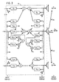
- Adaptive filter model M5 has a model input 92 receiving through summer 94 a noise signal from input microphone 54 correlated with noise from noise source 16.
- Model M5 has a model output 96 summed at summer 98 with the output of summer 100 which sums the outputs of error microphones 34 and 36.
- Model M5 has an error input 102 from the output of summer 98.
- Models M1 and M2 acoustically cancel noise in the respective outputs of error microphones 34 and 36, and model M5 electrically cancels noise in the outputs of error microphones 34 and 36.
- Summer 94 also has an input from audio source 104, which may for example be the audio system or the like of the automobile, to thus cancel such audio signal component in the signal supplied from summer 98 to speakers 30 and 32, such that a person at such locations hears only speech from locations 18 and 20 and not road noise nor noise from the automobile radio or audio system.
- Model M6 has a model input 106 from summer 94.
- Model M6 has a model output 108 summed at summer 110 with the output of summer 111 which sums the outputs of error microphones 38 and 40.
- Model M6 has an error input 112 from the output of summer 110.
- Model M6 electrically cancels noise from noise source 16 and audio noise or sound from source 104 in the signal transmitted to speakers 26 and 28.
- Model M7 has a model input 114 from the signal from error microphones 38 and 40, a model output 116 summed at summer 118 with the output of summer 98, and an error input 120 from the output of summer 118.
- Model M7 cancels the speech of a person at locations 22 or 24 in the signal sent to speakers 30 and 32 at such locations 22 and 24, to thus eliminate echo.
- Model M8 has a model input 122 from the signal from error microphones 34 and 36, a model output 124 supplied to summer 126, and an error input 128 from the output of summer 126.
- Model M8 cancels the speech of persons at locations 18 and 20 from the signal sent to speakers 26 and 28 at such locations 18 and 20, to eliminate echo.
- Each of models M5, M6, M7, M8 is preferably an FIR filter, though other types of adaptive filters may be used.
- Summer 130 has an input from model M1 and an input from summer 126, and has an output supplied to speaker 26.
- Summer 132 has an input from model M2 and an input from summer 126, and has an output supplied to speaker 28.
- Summer 134 has an input from model M3 and an input from summer 118, and has an output supplied to speaker 30.
- Summer 136 has an input from model M4 and an input from summer 118, and has an output supplied to speaker 32.
- each channel model M1, M2, M3, M4 has an error input from each of the error microphones 34, 36, 38, 40.
- the system includes a plurality of error paths, including a first set of error paths including an error path SE 11 to the first error microphone 34 from the first speaker 26, an error path SE 21 to the second error microphone 36 from the first speaker 26, an error path SE 31 to the third error microphone 38 from the first speaker 26, and an error path SE 41 to the fourth error microphone 40 from the first speaker 26, i.e. between speaker 26 and each of error microphones 34, 36, 38, 40.
- error paths from speaker 28 to each of error microphones 34, 36, 38, 40, and from speaker 30 to each of error microphones 34, 36, 38, 40, and from speaker 32 to each of error microphones 34, 36, 38, 40.
- these error paths are modeled, and the transfer functions thereof are provided in the channel models.
- M1 model input 42 is supplied through error path transfer function model SE 11 at 138, Fig. 2, and multiplied at multiplier 140 with the error signal e 1 from error microphone 34 to provide a weight update signal to summer 142.
- Model input 42 is supplied through the SE 21 error path transfer function model at 144 and multiplied at multiplier 146 with the error signal e 2 from error microphone 36 to provide a weight update signal to summer 142.
- Model input 42 is supplied through the error path SE 31 transfer function model at 148 and multiplied at multiplier 150 with error signal e 3 from error microphone 38 to provide a weight update signal to summer 142.
- Model input 42 is supplied through the error path SE 41 transfer function model at 152 and multiplied at multiplier 154 with error signal e 4 from error microphone 40 to provide a weight update signal to summer 142.
- the output of summer 142 provides the weight update signal for model M1.
- the multiple error signal processing for models M2, M3, M4 is comparable, and for which further reference may be had to U.S. Patents 5,216,721 and 5,216,722.
- models M1, M2, M3, M4 acoustically cancel or control noise, and models M5, M6, M7, M8 electrically cancel or control noise.
- Models M1, M2, M3, M4 preferably include SE modeling, as noted above, and as in U.S. Patents 5,216,721 and 5,216,722.
- Models M5, M6, M7, M8 do not include SE modeling.
- models M1, M2, M3, M4 are performed by a first processor operating at a low sampling rate, e.g. one or two kHz, and models M5, M6, M7, M8 are performed by a second processor operating at a substantially higher sampling rate, e.g. seven to ten kHz, over a broad frequency band because of the electrical cancellation.
- Fig. 3 herein is like Fig. 9 of U.S. Patent 5,216,721 and shows the generalized system for n input signals from n input transducers, n output signals to n output transducers, and n error signals from n error transducers, extrapolating the above system.
- Fig. 3 shows the m th input signal from the m th input transducer providing an input to algorithm filter A lm through A km through A mm through A nm .
- Algorithm filter A mm is updated by the weight update from the sum of the outputs of respective error path models SE lm through SE nm multiplied by respective error signals e l through e n .
- Algorithm filter A km is updated by the weight update from the sum of the outputs of respective error path models SE lk through SE nk multiplied by respective error signals e l through e n .
- the model output correction signal to the m th output transducer is applied to filter model B lm , which is the recursive transfer function in the first channel model from the m th output transducer, and so on through B km through B mm through B nm .
- Algorithm filter B mm is updated by the weight update from the sum of the outputs of respective SE error path models SE lm through SE nm multiplied by respective error signals e l through e n .
- Algorithm filter B km is updated by the weight update from the sum of the outputs of respective error path models SE lk through SE nk multiplied by respective error signals e l through e n .
- the system provides a multichannel generalized active acoustic attenuation system for complex sound fields. Each of the multiple channel models is intraconnected with all other channel models. The inputs and outputs of all channel models depend on the inputs and outputs of all other channel models. The total signal to the output transducers is used as an input to all other channel models. All error signals, e.g., e l ...e n , are used to update each channel.
- each channel has its own input transducer, output transducer, and error transducer, though other combinations are possible.
- a first channel may be the path from a first input transducer to a first output transducer
- a second channel may be the path from the first input transducer to a second output transducer.
- Each channel has a channel model, and each channel model is intraconnected with each of the remaining channel models, as above described.
- the system is applicable to one or more input transducers, one or more output transducers, and one or more error transducers, and at a minimum includes at least two input signals or at least two output transducers.
- One or more input signals representing the input acoustic wave providing the input noise are provided by respective input transducers, to the adaptive filter models. Only a single input signal need be provided, and the same such input signal may be input to each of the adaptive filter models.
- Such single input signal may be provided by a single input microphone, or alternatively the input signal may be provided by a transducer such as a tachometer which provides the frequency of a periodic input acoustic wave such as from an engine or the like.
- the input signal may be provided by one or more error signals, as above noted, in the case of a periodic noise source, "Active Adaptive Sound Control In A Duct: A Computer Simulation", J.C. Burgess, Journal of Acoustic Society of America, 70(3), September 1981, pages 715-726.
- the invention is further applicable as taught in U.S. Patent 5,216,722.
- Model inputs 42, 56, 68, 80 are provided from input microphone 54.
- various combinations of input arrays can be used, including a summed array of inputs.
- the inputs can be provided from a variety of microphones, accelerometers, transformer sensors, duct sensors, optical sensors, and other types of transducers.
- the sensor or transducer outputs can be summed in a summed array or a weighted array with adaptive filtering to optimize the input signal.
- the error signals can be a summed or weighted array.
- the error signals can be derived from error microphones mounted to occupant shoulder harnesses in a vehicle, to be described. The error sum could also be summed with ceiling microphones, headrest microphones, etc., or various combinations thereof.
- the canceling speakers can be the speakers of the vehicle audio system.
- the noted zones can be in vehicles such as cars, trucks, vans, buses, trains, ships, planes, etc.
- the zones can all be in the same vehicle, or one or more zones may be in a vehicle and other zones can be remote to the vehicle, including in other vehicles.
- the invention provides a communication system including a plurality of zones subject to noise from one or more noise sources, the noise being acoustical and/or electrical, one or more speaking locations in each zone such that a person at a speaking location is subject to noise from a noise source, a plurality of speakers, each introducing sound into a respective zone at a respective speaking location, a plurality of microphones each sensing noise and speech at a respective speaking location, a plurality of adaptive filter models each canceling noise from a respective noise source, each model having a model input from a reference signal correlated to the noise from the respective noise source, each model having a plurality of error inputs, each model having an output outputting a correction signal to cancel noise from the respective noise source, such that the output of the microphone carries a speech signal from a person at the speaking location but not a noise signal from the noise source, the output of at least one microphone carrying the speech of a first person at one speaking location being supplied to at least one speaker at another speaking location, such that a second person at the
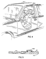
- Figs. 4 and 5 show a particularly desirable embodiment for ease of use in a vehicle.
- At least one of the noted zones is in a vehicle 202 having an occupant restraint system 204 including a shoulder harness 206.
- At least one error microphone 208 is mounted to the shoulder harness.
- the shoulder harness includes a mesh belt 210. Error microphone 208 is embedded in the mesh belt or mounted thereto by a sound-transmissive layer or tape member 211 and has a connection wire 212 running along the belt and enmeshed therein, such that the error microphone and connection wire are part of the belt.
- the error microphone is automatically positioned in a proper location upon deployment of the belt.
- wire 212 is connected to a seatbelt interlock 213, such as the seatbelt anchor, to provide feedback information confirming deployment of the belt and the presence of an occupant at the respective location.
- a wireless microphone 208 is used.
Landscapes
- Physics & Mathematics (AREA)
- Engineering & Computer Science (AREA)
- Acoustics & Sound (AREA)
- Multimedia (AREA)
- Health & Medical Sciences (AREA)
- Audiology, Speech & Language Pathology (AREA)
- General Health & Medical Sciences (AREA)
- Soundproofing, Sound Blocking, And Sound Damping (AREA)
- Fittings On The Vehicle Exterior For Carrying Loads, And Devices For Holding Or Mounting Articles (AREA)
- Mobile Radio Communication Systems (AREA)
Claims (16)
- Système de communication multivoie, comprenant :plusieurs zones (12, 14) soumises à du bruit provenant d'une ou de plusieurs sources de bruit (16) ;un ou plusieurs emplacements de conversation (18, 20, 22, 24) dans chaque zone (12, 14), si bien qu'une personne se trouvant au niveau d'un emplacement de conversation est soumise à du bruit provenant d'une source de bruit (16) ;plusieurs haut-parleurs (26, 28, 30, 32), introduisant chacun du son dans une zone (12, 14) respective au niveau d'un emplacement respectif de conversation (18, 20, 22, 24) ;plusieurs microphones à détection d'erreurs (30, 32, 34, 36), détectant chacun le bruit et la parole au niveau d'un emplacement respectif de conversation (18, 20, 22, 24) ;plusieurs modèles de filtres adaptatifs (M1 à M4), supprimant chacun le bruit provenant d'une source respective de bruit, chaque modèle (M1 à M4) ayant une entrée de modèle provenant d'un signal de référence, en corrélation avec ledit bruit provenant de ladite source respective de bruit, chaque modèle (M1 à M4) ayant plusieurs entrées d'erreurs (44, 46, 48, 50), provenant chacune de chacun desdits plusieurs microphones à détection d'erreurs (30, 32, 34, 36), chaque modèle ayant une sortie (52, 66, 78, 90) qui fournit un signal de correction pour supprimer le bruit provenant de la source respective de bruit, de telle manière que la sortie du microphone à détection d'erreurs (30, 32, 34, 36) achemine un signal de parole provenant d'une personne située au niveau de l'emplacement de conversation, mais non pas un signal de bruit provenant de la source de bruit ;la sortie d'au moins un microphone à détection d'erreurs (30, 32, 34, 36), acheminant la parole d'une première personne située au niveau d'un emplacement de conversation, étant fournie à au moins un haut-parleur (26, 28, 30, 32) au niveau d'un autre emplacement de conversation, de telle manière qu'une deuxième personne, située au niveau dudit autre emplacement de conversation, puisse entendre la parole de ladite première personne située au niveau dudit emplacement de conversation.
- Système de communication selon la revendication 1, qui est un système d'atténuation acoustique active, dans lequel chaque modèle des plusieurs modèles de filtres adaptatifs supprime le bruit provenant d'une source respective de bruit au niveau d'un emplacement respectif de conversation, tel qu'il est détecté par un microphone respectif à détection d'erreurs, et chaque modèle ayant une sortie qui produit un signal de correction pour introduire un son d'annulation au niveau de l'emplacement respectif de conversation.
- Système selon la revendication 1 ou la revendication 2, comprenant un premier ensemble de plusieurs modèles de filtres adaptatifs (M1 à M4), qui suppriment chacun le bruit d'une manière acoustique, et un deuxième ensemble de plusieurs modèles de filtres adaptatifs (M5 à M8), qui suppriment chacun le bruit d'une manière électrique.
- Système selon la revendication 3, dans lequel ledit premier ensemble de modèles (M1 à M4) comprend la modélisation d'au moins l'un d'un haut-parleur respectif et du trajet respectif entre le haut-parleur et un microphone respectif à détection d'erreurs, et dans lequel ledit deuxième ensemble de modèles (M5 à M8) est commandé à une cadence d'échantillonnage sensiblement plus élevée que celle dudit premier ensemble de modèles.
- Système selon la revendication 2, dans lequel au moins un modèle dudit deuxième ensemble a une entrée de modèle provenant d'un sommateur, qui effectue la somme dudit bruit et d'un signal audio désigné, pour supprimer ledit signal audio désigné au niveau de l'emplacement respectif de conversation.
- Système selon la revendication 1, dans lequel au moins l'un desdits modèles (M5, M6) a une entrée de modèle provenant d'un sommateur (94), qui effectue la somme dudit bruit (16) et d'un signal audio désigné.
- Système selon la revendication 1 ou la revendication 2, dans lequel au moins l'une desdites zones se trouve dans un véhicule (202) comportant un système de retenue d'occupant (204), comprenant un baudrier (206), et dans lequel au moins l'un desdits microphones (208) est monté dans ledit baudrier (206).
- Système selon la revendication 1 ou la revendication 2, dans lequel chacune desdites zones (12, 14) se trouve dans un véhicule (202).
- Système selon la revendication 8, dans lequel toutes lesdites zones (12, 14) se trouvent dans le même véhicule (202).
- Système selon la revendication 1 ou la revendication 2, dans lequel au moins l'une desdites zones (12, 14) se trouve dans un véhicule (202), et au moins une autre desdites zones (12, 14) est extérieure audit véhicule (202).
- Système selon la revendication 2, comprenant :une première (12) desdites zones comprenant des premier et deuxième emplacements de conversation (18, 20) ;une deuxième (14) desdites zones comprenant des troisième et quatrième emplacements de conversation (22, 24) ;un premier (26) desdits haut-parleurs, situé au niveau dudit premier emplacement de conversation (18) ;un deuxième (28) desdits haut-parleurs, situé au niveau dudit deuxième emplacement de conversation (20) ;un troisième (30) desdits haut-parleurs, situé au niveau dudit troisième emplacement de conversation (22) ;un quatrième (32) desdits haut-parleurs, situé au niveau dudit quatrième emplacement de conversation (24) ;un premier (34) desdits microphones à détection d'erreurs, situé au niveau dudit premier emplacement de conversation (18) ;un deuxième (36) desdits microphones à détection d'erreurs, situé au niveau dudit deuxième emplacement de conversation (20) ;un troisième (38) desdits microphones à détection d'erreurs, situé au niveau dudit troisième emplacement de conversation (22) ;un quatrième (40) desdits microphones à détection d'erreurs, situé au niveau dudit quatrième emplacement de conversation (24) ;un premier (M1) desdits modèles ayant une sortie de modèle (52) vers ledit premier haut-parleur (26), et des première, deuxième, troisième et quatrième entrées d'erreurs (44, 46, 48, 50), provenant respectivement desdits premier, deuxième, troisième et quatrième microphones à détection d'erreurs (34, 36, 38, 40) ;un deuxième (M2) desdits modèles ayant une sortie de modèle (66) vers ledit deuxième haut-parleur (28), et des première, deuxième, troisième et quatrième entrées d'erreurs (58, 60, 62, 64), provenant respectivement desdits premier, deuxième, troisième et quatrième microphones à détection d'erreurs (34, 36, 38, 40) ;un troisième (M3) desdits modèles ayant une sortie de modèle (78) vers ledit troisième haut-parleur (30), et des première, deuxième, troisième et quatrième entrées d'erreurs (70, 72, 74, 76), provenant respectivement desdits premier, deuxième, troisième et quatrième microphones à détection d'erreurs (34, 36, 38, 40) ;un quatrième (M4) desdits modèles ayant une sortie de modèle (90) vers ledit quatrième haut-parleur (32), et des première, deuxième, troisième et quatrième entrées d'erreurs (82, 84, 86, 88), provenant respectivement desdits premier, deuxième, troisième et quatrième microphones à détection d'erreurs (34, 36, 38, 40).
- Système selon la revendication 11, dans lequel lesdites première et deuxième zones (12, 14) sont soumises à du bruit provenant d'une source commune de bruit (16), et chacun desdits premier, deuxième, troisième et quatrième modèles (M1 à M4) a une entrée de modèle, qui reçoit un signal commun de référence en corrélation avec le bruit provenant de ladite source commune de bruit.
- Système selon la revendication 11, comprenant :un cinquième modèle de filtre adaptatif (M5) ;un sixième modèle de filtre adaptatif (M6) ;un septième modèle de filtre adaptatif (M7) ;un huitième modèle de filtre adaptatif (M8) ;un premier sommateur (130) ayant une entrée provenant dudit premier modèle (M1), et une sortie fournie audit premier haut-parleur (26) ;un deuxième sommateur (132) ayant une entrée provenant dudit deuxième modèle (M2), et une sortie fournie audit deuxième haut-parleur (28) ;un troisième sommateur (134) ayant une entrée provenant dudit troisième modèle (M3), et une sortie fournie audit troisième haut-parleur (30) ;un quatrième sommateur (136) ayant une entrée provenant dudit quatrième modèle (M4), et une sortie fournie audit quatrième haut-parleur (32) ;un cinquième sommateur (98) ayant une entrée provenant dudit cinquième modèle (M5) ;un sixième sommateur (110) ayant une entrée provenant dudit sixième modèle (M6) ;un septième sommateur (118) ayant une entrée provenant dudit septième modèle (M7) ;un huitième sommateur (126) ayant une entrée provenant dudit huitième modèle (M8) ;un neuvième sommateur (100) ayant une entrée. provenant dudit premier microphone à détection d'erreurs (34) et une autre entrée provenant dudit deuxième microphone à détection d'erreurs (36), et ayant une sortie fournie audit cinquième sommateur (98) ;un dixième sommateur (111) ayant une entrée provenant dudit troisième microphone à détection d'erreurs (38) et une autre entrée provenant dudit quatrième microphone à détection d'erreurs (40), et ayant une sortie fournie audit sixième sommateur (110) ;ledit cinquième sommateur (98) ayant une sortie fournie audit septième sommateur (118) et à une entrée d'erreur dudit cinquième modèle (M5) ;ledit sixième sommateur (110) ayant une sortie fournie audit huitième sommateur (126) et à une entrée d'erreur dudit sixième modèle (M6) ;ledit septième sommateur (118) ayant une sortie fournie auxdits troisième et quatrième sommateurs (134, 136) et à une entrée de modèle dudit huitième modèle (M8) et à une entrée d'erreur dudit septième modèle (M7) ;ledit huitième sommateur (126) ayant une sortie fournie auxdits premier et deuxième sommateurs (130, 132) et à une entrée de modèle dudit septième modèle (M7) et à une entrée d'erreur dudit huitième modèle (M8).
- Système selon la revendication 13, dans lequel chacune desdites première et deuxième zones (12, 14) est soumise à du bruit provenant d'une source commune de bruit (16), et chacun desdits premier, deuxième, troisième, quatrième, cinquième et sixième modèles (M1 à M6) a une entrée de modèle, qui reçoit un signal commun de référence en corrélation avec le bruit provenant de ladite source commune de bruit (16).
- Système selon la revendication 14, comprenant un onzième sommateur (94) ayant une entrée provenant dudit signal commun de référence et une autre entrée provenant d'un signal audio désigné (104), et ayant une sortie fournie auxdites entrées de modèle desdits cinquième et sixième modèles (M5, M6).
- Système selon la revendication 1, comprenant plusieurs autres modèles de filtres adaptatifs, supprimant chacun la parole d'une personne située dans une zone donnée, à partir du signal envoyé à un haut-parleur dans ladite zone donnée, et provenant d'un microphone à détection d'erreurs situé dans une autre zone.
Applications Claiming Priority (2)
| Application Number | Priority Date | Filing Date | Title |
|---|---|---|---|
| US08/368,920 US5602928A (en) | 1995-01-05 | 1995-01-05 | Multi-channel communication system |
| US368920 | 2003-02-18 |
Publications (3)
| Publication Number | Publication Date |
|---|---|
| EP0721178A2 EP0721178A2 (fr) | 1996-07-10 |
| EP0721178A3 EP0721178A3 (fr) | 1998-12-09 |
| EP0721178B1 true EP0721178B1 (fr) | 2003-05-14 |
Family
ID=23453303
Family Applications (1)
| Application Number | Title | Priority Date | Filing Date |
|---|---|---|---|
| EP96300078A Expired - Lifetime EP0721178B1 (fr) | 1995-01-05 | 1996-01-04 | Système de communication multi-canaux |
Country Status (4)
| Country | Link |
|---|---|
| US (1) | US5602928A (fr) |
| EP (1) | EP0721178B1 (fr) |
| CA (1) | CA2166572A1 (fr) |
| DE (1) | DE69628061T2 (fr) |
Cited By (1)
| Publication number | Priority date | Publication date | Assignee | Title |
|---|---|---|---|---|
| DE102004039066B4 (de) * | 2003-09-16 | 2015-03-12 | Volkswagen Ag | Audiosystem für ein Kraftfahrzeug |
Families Citing this family (41)
| Publication number | Priority date | Publication date | Assignee | Title |
|---|---|---|---|---|
| US5706344A (en) * | 1996-03-29 | 1998-01-06 | Digisonix, Inc. | Acoustic echo cancellation in an integrated audio and telecommunication system |
| US5917920A (en) * | 1997-05-29 | 1999-06-29 | Humphries; Alan | Safety vehicle communication system |
| US6535609B1 (en) | 1997-06-03 | 2003-03-18 | Lear Automotive Dearborn, Inc. | Cabin communication system |
| US5987106A (en) * | 1997-06-24 | 1999-11-16 | Ati Technologies, Inc. | Automatic volume control system and method for use in a multimedia computer system |
| US6430295B1 (en) | 1997-07-11 | 2002-08-06 | Telefonaktiebolaget Lm Ericsson (Publ) | Methods and apparatus for measuring signal level and delay at multiple sensors |
| US6704421B1 (en) | 1997-07-24 | 2004-03-09 | Ati Technologies, Inc. | Automatic multichannel equalization control system for a multimedia computer |
| US6496581B1 (en) * | 1997-09-11 | 2002-12-17 | Digisonix, Inc. | Coupled acoustic echo cancellation system |
| US6295364B1 (en) | 1998-03-30 | 2001-09-25 | Digisonix, Llc | Simplified communication system |
| US6055502A (en) * | 1997-09-27 | 2000-04-25 | Ati Technologies, Inc. | Adaptive audio signal compression computer system and method |
| US6674864B1 (en) | 1997-12-23 | 2004-01-06 | Ati Technologies | Adaptive speaker compensation system for a multimedia computer system |
| DE19812697A1 (de) | 1998-03-23 | 1999-09-30 | Volkswagen Ag | Verfahren und Einrichtung zum Betrieb einer Mikrofonanordnung, insbesondere in einem Kraftfahrzeug |
| US6195435B1 (en) | 1998-05-01 | 2001-02-27 | Ati Technologies | Method and system for channel balancing and room tuning for a multichannel audio surround sound speaker system |
| US6438247B1 (en) * | 1999-01-28 | 2002-08-20 | International Business Machines Corporation | Seatbelt microphone mounting |
| DE19938158C1 (de) * | 1999-08-16 | 2001-01-11 | Daimler Chrysler Ag | Verfahren und Vorrichtung sowie ihre Verwendung zur Kompensation von Verlusten eines akustischen Signals |
| DE19942868A1 (de) | 1999-09-08 | 2001-03-15 | Volkswagen Ag | Verfahren zum Betrieb einer Mehrfachmikrofonanordnung in einem Kraftfahrzeug sowie Mehrfachmikrofonanordnung selbst |
| DE19958836A1 (de) * | 1999-11-29 | 2001-05-31 | Deutsche Telekom Ag | Verfahren und Anordnung zur Verbesserung der Kommunikation in einem Fahrzeug |
| ATE248497T1 (de) * | 1999-12-09 | 2003-09-15 | Frederick Johannes Bruwer | Sprachsverteilungssystem |
| EP1143411A3 (fr) * | 2000-04-06 | 2004-11-03 | Siemens VDO Automotive Inc. | Solution stable pour la suppression active du bruit |
| US20010046300A1 (en) * | 2000-04-17 | 2001-11-29 | Mclean Ian R. | Offline active control of automotive noise |
| ES2228705T3 (es) * | 2000-07-13 | 2005-04-16 | Paragon Ag | Dispositivo de manos libres. |
| US20020039422A1 (en) * | 2000-09-20 | 2002-04-04 | Daly Paul D. | Driving mode for active noise cancellation |
| US20020076058A1 (en) * | 2000-12-19 | 2002-06-20 | Astorino John Frank | Engine rotation reference signal for noise attenuation |
| US6549629B2 (en) | 2001-02-21 | 2003-04-15 | Digisonix Llc | DVE system with normalized selection |
| US6594368B2 (en) | 2001-02-21 | 2003-07-15 | Digisonix, Llc | DVE system with dynamic range processing |
| US6717537B1 (en) | 2001-06-26 | 2004-04-06 | Sonic Innovations, Inc. | Method and apparatus for minimizing latency in digital signal processing systems |
| US20030112981A1 (en) * | 2001-12-17 | 2003-06-19 | Siemens Vdo Automotive, Inc. | Active noise control with on-line-filtered C modeling |
| EP1860911A1 (fr) * | 2006-05-24 | 2007-11-28 | Harman/Becker Automotive Systems GmbH | Système et procédé pour améliorer la communication dans un espace |
| JP4958154B2 (ja) * | 2006-11-29 | 2012-06-20 | 本田技研工業株式会社 | 自動二輪車 |
| US9560448B2 (en) * | 2007-05-04 | 2017-01-31 | Bose Corporation | System and method for directionally radiating sound |
| US9247346B2 (en) | 2007-12-07 | 2016-01-26 | Northern Illinois Research Foundation | Apparatus, system and method for noise cancellation and communication for incubators and related devices |
| US9020158B2 (en) * | 2008-11-20 | 2015-04-28 | Harman International Industries, Incorporated | Quiet zone control system |
| US8135140B2 (en) | 2008-11-20 | 2012-03-13 | Harman International Industries, Incorporated | System for active noise control with audio signal compensation |
| US8718289B2 (en) * | 2009-01-12 | 2014-05-06 | Harman International Industries, Incorporated | System for active noise control with parallel adaptive filter configuration |
| EP2211564B1 (fr) * | 2009-01-23 | 2014-09-10 | Harman Becker Automotive Systems GmbH | Système de communication pour compartiment de passagers |
| US8189799B2 (en) * | 2009-04-09 | 2012-05-29 | Harman International Industries, Incorporated | System for active noise control based on audio system output |
| US8199924B2 (en) * | 2009-04-17 | 2012-06-12 | Harman International Industries, Incorporated | System for active noise control with an infinite impulse response filter |
| US8077873B2 (en) * | 2009-05-14 | 2011-12-13 | Harman International Industries, Incorporated | System for active noise control with adaptive speaker selection |
| US9131915B2 (en) | 2011-07-06 | 2015-09-15 | University Of New Brunswick | Method and apparatus for noise cancellation |
| EP3144928B1 (fr) | 2015-09-15 | 2021-03-24 | Harman Becker Automotive Systems GmbH | Système de suppression du bruit de la route actif |
| US10283106B1 (en) * | 2018-03-28 | 2019-05-07 | Cirrus Logic, Inc. | Noise suppression |
| WO2020052759A1 (fr) * | 2018-09-13 | 2020-03-19 | Harman Becker Automotive Systems Gmbh | Génération de zone silencieuse |
Family Cites Families (9)
| Publication number | Priority date | Publication date | Assignee | Title |
|---|---|---|---|---|
| US4677676A (en) * | 1986-02-11 | 1987-06-30 | Nelson Industries, Inc. | Active attenuation system with on-line modeling of speaker, error path and feedback pack |
| US5033082A (en) * | 1989-07-31 | 1991-07-16 | Nelson Industries, Inc. | Communication system with active noise cancellation |
| JP2748626B2 (ja) * | 1989-12-29 | 1998-05-13 | 日産自動車株式会社 | 能動型騒音制御装置 |
| US5216721A (en) * | 1991-04-25 | 1993-06-01 | Nelson Industries, Inc. | Multi-channel active acoustic attenuation system |
| US5216722A (en) * | 1991-11-15 | 1993-06-01 | Nelson Industries, Inc. | Multi-channel active attenuation system with error signal inputs |
| JP2921232B2 (ja) * | 1991-12-27 | 1999-07-19 | 日産自動車株式会社 | 能動型不快波制御装置 |
| EP0560364B1 (fr) * | 1992-03-12 | 1998-10-28 | Honda Giken Kogyo Kabushiki Kaisha | Système de régulation des vibrations et du bruit pour véhicules automobiles |
| JPH084243B2 (ja) * | 1993-05-31 | 1996-01-17 | 日本電気株式会社 | 多チャンネルエコー除去方法および装置 |
| US5327496A (en) * | 1993-06-30 | 1994-07-05 | Iowa State University Research Foundation, Inc. | Communication device, apparatus, and method utilizing pseudonoise signal for acoustical echo cancellation |
-
1995
- 1995-01-05 US US08/368,920 patent/US5602928A/en not_active Expired - Lifetime
-
1996
- 1996-01-04 EP EP96300078A patent/EP0721178B1/fr not_active Expired - Lifetime
- 1996-01-04 CA CA002166572A patent/CA2166572A1/fr not_active Abandoned
- 1996-01-04 DE DE69628061T patent/DE69628061T2/de not_active Expired - Lifetime
Cited By (1)
| Publication number | Priority date | Publication date | Assignee | Title |
|---|---|---|---|---|
| DE102004039066B4 (de) * | 2003-09-16 | 2015-03-12 | Volkswagen Ag | Audiosystem für ein Kraftfahrzeug |
Also Published As
| Publication number | Publication date |
|---|---|
| EP0721178A3 (fr) | 1998-12-09 |
| US5602928A (en) | 1997-02-11 |
| EP0721178A2 (fr) | 1996-07-10 |
| DE69628061T2 (de) | 2004-04-01 |
| DE69628061D1 (de) | 2003-06-18 |
| CA2166572A1 (fr) | 1996-07-06 |
Similar Documents
| Publication | Publication Date | Title |
|---|---|---|
| EP0721178B1 (fr) | Système de communication multi-canaux | |
| EP0411801B1 (fr) | Dispositif de communication avec suppression active du bruit | |
| CN101292567B (zh) | 噪声控制装置 | |
| US5425105A (en) | Multiple adaptive filter active noise canceller | |
| EP0542457B1 (fr) | Dispositif d'atténuation active à canaux multiples avec entrées de signaux d'erreur | |
| EP0903726B1 (fr) | Système acoustique et actif d'élimination de bruit et d'écho | |
| US20020071573A1 (en) | DVE system with customized equalization | |
| JP7149336B2 (ja) | フィードバック補償を用いたアクティブノイズコントロール | |
| EP3759708B1 (fr) | Commande active du bruit prédictive | |
| EP2629289B1 (fr) | Système de contrôle actif de bruit avec rétroaction et une voie secondaire longue | |
| US7191124B2 (en) | Voice input and output apparatus with balancing among sound pressures at control points in a sound field | |
| JP2894035B2 (ja) | 能動型騒音制御装置 | |
| JP3377220B2 (ja) | スピーチプライバシー保護装置 | |
| WO1994029846A1 (fr) | Cabine pour operateur de vehicule a suppression du bruit active dans un espace tridimensionnel | |
| EP1261961B1 (fr) | Procedes et systemes de reduction de bruit pour sources de signal decalees dans l'espace | |
| CN117095665A (zh) | 主动型噪音控制系统 | |
| JP3384493B2 (ja) | 車室内こもり音低減装置 | |
| JPH06161468A (ja) | 騒音消去装置と車載用音響装置 | |
| EP4057275B1 (fr) | Système de commande de bruit actif | |
| JP3144569B2 (ja) | 車両用騒音制御装置 | |
| JPH0895579A (ja) | 車室内騒音低減装置 | |
| JPH06167985A (ja) | 能動型騒音制御装置 | |
| JPH11332000A (ja) | 動的信号処理装置の内部パラメータ決定方法及び電気音響装置 | |
| JPH0546182A (ja) | 車載オーデイオ・ノイズキヤンセラ装置 | |
| JPH0511775A (ja) | 騒音キヤンセル方式 |
Legal Events
| Date | Code | Title | Description |
|---|---|---|---|
| PUAI | Public reference made under article 153(3) epc to a published international application that has entered the european phase |
Free format text: ORIGINAL CODE: 0009012 |
|
| AK | Designated contracting states |
Kind code of ref document: A2 Designated state(s): DE FR GB IT NL SE |
|
| PUAL | Search report despatched |
Free format text: ORIGINAL CODE: 0009013 |
|
| AK | Designated contracting states |
Kind code of ref document: A3 Designated state(s): DE FR GB IT NL SE |
|
| 17P | Request for examination filed |
Effective date: 19990512 |
|
| 17Q | First examination report despatched |
Effective date: 20010928 |
|
| GRAH | Despatch of communication of intention to grant a patent |
Free format text: ORIGINAL CODE: EPIDOS IGRA |
|
| GRAH | Despatch of communication of intention to grant a patent |
Free format text: ORIGINAL CODE: EPIDOS IGRA |
|
| GRAA | (expected) grant |
Free format text: ORIGINAL CODE: 0009210 |
|
| AK | Designated contracting states |
Designated state(s): DE FR GB IT NL SE |
|
| PG25 | Lapsed in a contracting state [announced via postgrant information from national office to epo] |
Ref country code: NL Free format text: LAPSE BECAUSE OF FAILURE TO SUBMIT A TRANSLATION OF THE DESCRIPTION OR TO PAY THE FEE WITHIN THE PRESCRIBED TIME-LIMIT Effective date: 20030514 Ref country code: IT Free format text: LAPSE BECAUSE OF FAILURE TO SUBMIT A TRANSLATION OF THE DESCRIPTION OR TO PAY THE FEE WITHIN THE PRESCRIBED TIME-LIMIT;WARNING: LAPSES OF ITALIAN PATENTS WITH EFFECTIVE DATE BEFORE 2007 MAY HAVE OCCURRED AT ANY TIME BEFORE 2007. THE CORRECT EFFECTIVE DATE MAY BE DIFFERENT FROM THE ONE RECORDED. Effective date: 20030514 Ref country code: FR Free format text: LAPSE BECAUSE OF FAILURE TO SUBMIT A TRANSLATION OF THE DESCRIPTION OR TO PAY THE FEE WITHIN THE PRESCRIBED TIME-LIMIT Effective date: 20030514 |
|
| REG | Reference to a national code |
Ref country code: GB Ref legal event code: FG4D |
|
| REF | Corresponds to: |
Ref document number: 69628061 Country of ref document: DE Date of ref document: 20030618 Kind code of ref document: P |
|
| PG25 | Lapsed in a contracting state [announced via postgrant information from national office to epo] |
Ref country code: SE Free format text: LAPSE BECAUSE OF FAILURE TO SUBMIT A TRANSLATION OF THE DESCRIPTION OR TO PAY THE FEE WITHIN THE PRESCRIBED TIME-LIMIT Effective date: 20030814 |
|
| NLV1 | Nl: lapsed or annulled due to failure to fulfill the requirements of art. 29p and 29m of the patents act | ||
| PLBE | No opposition filed within time limit |
Free format text: ORIGINAL CODE: 0009261 |
|
| STAA | Information on the status of an ep patent application or granted ep patent |
Free format text: STATUS: NO OPPOSITION FILED WITHIN TIME LIMIT |
|
| 26N | No opposition filed |
Effective date: 20040217 |
|
| EN | Fr: translation not filed | ||
| PGFP | Annual fee paid to national office [announced via postgrant information from national office to epo] |
Ref country code: DE Payment date: 20150128 Year of fee payment: 20 |
|
| PGFP | Annual fee paid to national office [announced via postgrant information from national office to epo] |
Ref country code: GB Payment date: 20150127 Year of fee payment: 20 |
|
| REG | Reference to a national code |
Ref country code: DE Ref legal event code: R071 Ref document number: 69628061 Country of ref document: DE |
|
| REG | Reference to a national code |
Ref country code: GB Ref legal event code: PE20 Expiry date: 20160103 |
|
| PG25 | Lapsed in a contracting state [announced via postgrant information from national office to epo] |
Ref country code: GB Free format text: LAPSE BECAUSE OF EXPIRATION OF PROTECTION Effective date: 20160103 |