EP0721843B1 - Tête d'éjection de liquide, dispositif d'éjection de liquide et procédé d'éjection de liquide - Google Patents
Tête d'éjection de liquide, dispositif d'éjection de liquide et procédé d'éjection de liquide Download PDFInfo
- Publication number
- EP0721843B1 EP0721843B1 EP96300244A EP96300244A EP0721843B1 EP 0721843 B1 EP0721843 B1 EP 0721843B1 EP 96300244 A EP96300244 A EP 96300244A EP 96300244 A EP96300244 A EP 96300244A EP 0721843 B1 EP0721843 B1 EP 0721843B1
- Authority
- EP
- European Patent Office
- Prior art keywords
- liquid
- movable member
- bubble
- ejection
- head
- Prior art date
- Legal status (The legal status is an assumption and is not a legal conclusion. Google has not performed a legal analysis and makes no representation as to the accuracy of the status listed.)
- Expired - Lifetime
Links
- 239000007788 liquid Substances 0.000 title claims abstract description 664
- 238000000034 method Methods 0.000 title abstract description 30
- 239000000463 material Substances 0.000 claims description 71
- 238000011144 upstream manufacturing Methods 0.000 claims description 32
- 230000020169 heat generation Effects 0.000 claims description 28
- 238000005192 partition Methods 0.000 claims description 27
- 230000033001 locomotion Effects 0.000 claims description 23
- 229920005989 resin Polymers 0.000 claims description 20
- 239000011347 resin Substances 0.000 claims description 20
- 230000000694 effects Effects 0.000 claims description 14
- 238000011049 filling Methods 0.000 claims description 14
- 230000006870 function Effects 0.000 claims description 13
- 229910052751 metal Inorganic materials 0.000 claims description 10
- 239000002184 metal Substances 0.000 claims description 10
- 230000004044 response Effects 0.000 claims description 7
- 239000004753 textile Substances 0.000 claims description 6
- 229910010293 ceramic material Inorganic materials 0.000 claims description 5
- 239000000123 paper Substances 0.000 claims description 5
- 239000010985 leather Substances 0.000 claims description 4
- 239000000088 plastic resin Substances 0.000 claims description 4
- 238000007781 pre-processing Methods 0.000 claims description 4
- 238000012805 post-processing Methods 0.000 claims description 3
- 239000002023 wood Substances 0.000 claims description 3
- 239000003086 colorant Substances 0.000 claims description 2
- 230000001737 promoting effect Effects 0.000 claims description 2
- 230000000452 restraining effect Effects 0.000 claims 10
- 230000001419 dependent effect Effects 0.000 claims 2
- 239000000976 ink Substances 0.000 description 81
- 239000000758 substrate Substances 0.000 description 22
- 230000001976 improved effect Effects 0.000 description 15
- 238000007639 printing Methods 0.000 description 15
- 230000001105 regulatory effect Effects 0.000 description 14
- 230000005499 meniscus Effects 0.000 description 13
- 238000004891 communication Methods 0.000 description 11
- 239000000203 mixture Substances 0.000 description 11
- 238000000926 separation method Methods 0.000 description 11
- 230000008093 supporting effect Effects 0.000 description 11
- 238000010438 heat treatment Methods 0.000 description 10
- -1 thread Substances 0.000 description 10
- LFQSCWFLJHTTHZ-UHFFFAOYSA-N Ethanol Chemical compound CCO LFQSCWFLJHTTHZ-UHFFFAOYSA-N 0.000 description 9
- PXHVJJICTQNCMI-UHFFFAOYSA-N nickel Substances [Ni] PXHVJJICTQNCMI-UHFFFAOYSA-N 0.000 description 9
- 230000008569 process Effects 0.000 description 9
- XLYOFNOQVPJJNP-UHFFFAOYSA-N water Substances O XLYOFNOQVPJJNP-UHFFFAOYSA-N 0.000 description 9
- 239000012530 fluid Substances 0.000 description 8
- 238000006073 displacement reaction Methods 0.000 description 7
- 230000006872 improvement Effects 0.000 description 7
- VYPSYNLAJGMNEJ-UHFFFAOYSA-N Silicium dioxide Chemical compound O=[Si]=O VYPSYNLAJGMNEJ-UHFFFAOYSA-N 0.000 description 6
- 230000008859 change Effects 0.000 description 6
- 238000012545 processing Methods 0.000 description 6
- 230000009471 action Effects 0.000 description 5
- 229910052782 aluminium Inorganic materials 0.000 description 5
- XAGFODPZIPBFFR-UHFFFAOYSA-N aluminium Chemical compound [Al] XAGFODPZIPBFFR-UHFFFAOYSA-N 0.000 description 5
- 150000001875 compounds Chemical class 0.000 description 5
- 230000008021 deposition Effects 0.000 description 5
- 238000004519 manufacturing process Methods 0.000 description 5
- 238000002156 mixing Methods 0.000 description 5
- 229910052715 tantalum Inorganic materials 0.000 description 5
- GUVRBAGPIYLISA-UHFFFAOYSA-N tantalum atom Chemical compound [Ta] GUVRBAGPIYLISA-UHFFFAOYSA-N 0.000 description 5
- OKKJLVBELUTLKV-UHFFFAOYSA-N Methanol Chemical group OC OKKJLVBELUTLKV-UHFFFAOYSA-N 0.000 description 4
- PCHJSUWPFVWCPO-UHFFFAOYSA-N gold Chemical compound [Au] PCHJSUWPFVWCPO-UHFFFAOYSA-N 0.000 description 4
- 229910052737 gold Inorganic materials 0.000 description 4
- 239000010931 gold Substances 0.000 description 4
- 229910052759 nickel Inorganic materials 0.000 description 4
- 239000004033 plastic Substances 0.000 description 4
- 229920003023 plastic Polymers 0.000 description 4
- 230000002265 prevention Effects 0.000 description 4
- ZWEHNKRNPOVVGH-UHFFFAOYSA-N 2-Butanone Chemical compound CCC(C)=O ZWEHNKRNPOVVGH-UHFFFAOYSA-N 0.000 description 3
- CSCPPACGZOOCGX-UHFFFAOYSA-N Acetone Chemical compound CC(C)=O CSCPPACGZOOCGX-UHFFFAOYSA-N 0.000 description 3
- XEKOWRVHYACXOJ-UHFFFAOYSA-N Ethyl acetate Chemical compound CCOC(C)=O XEKOWRVHYACXOJ-UHFFFAOYSA-N 0.000 description 3
- KFZMGEQAYNKOFK-UHFFFAOYSA-N Isopropanol Chemical compound CC(C)O KFZMGEQAYNKOFK-UHFFFAOYSA-N 0.000 description 3
- 229920000106 Liquid crystal polymer Polymers 0.000 description 3
- 239000004977 Liquid-crystal polymers (LCPs) Substances 0.000 description 3
- IMNFDUFMRHMDMM-UHFFFAOYSA-N N-Heptane Chemical compound CCCCCCC IMNFDUFMRHMDMM-UHFFFAOYSA-N 0.000 description 3
- 239000004952 Polyamide Substances 0.000 description 3
- 229910052581 Si3N4 Inorganic materials 0.000 description 3
- RTAQQCXQSZGOHL-UHFFFAOYSA-N Titanium Chemical compound [Ti] RTAQQCXQSZGOHL-UHFFFAOYSA-N 0.000 description 3
- YXFVVABEGXRONW-UHFFFAOYSA-N Toluene Chemical compound CC1=CC=CC=C1 YXFVVABEGXRONW-UHFFFAOYSA-N 0.000 description 3
- XSQUKJJJFZCRTK-UHFFFAOYSA-N Urea Chemical compound NC(N)=O XSQUKJJJFZCRTK-UHFFFAOYSA-N 0.000 description 3
- 238000009825 accumulation Methods 0.000 description 3
- 229910045601 alloy Inorganic materials 0.000 description 3
- 239000000956 alloy Substances 0.000 description 3
- 238000009835 boiling Methods 0.000 description 3
- 230000008602 contraction Effects 0.000 description 3
- 238000010586 diagram Methods 0.000 description 3
- MTHSVFCYNBDYFN-UHFFFAOYSA-N diethylene glycol Chemical compound OCCOCCO MTHSVFCYNBDYFN-UHFFFAOYSA-N 0.000 description 3
- 239000000428 dust Substances 0.000 description 3
- 239000007769 metal material Substances 0.000 description 3
- 229920002647 polyamide Polymers 0.000 description 3
- 230000009467 reduction Effects 0.000 description 3
- 238000009877 rendering Methods 0.000 description 3
- HQVNEWCFYHHQES-UHFFFAOYSA-N silicon nitride Chemical compound N12[Si]34N5[Si]62N3[Si]51N64 HQVNEWCFYHHQES-UHFFFAOYSA-N 0.000 description 3
- 230000006641 stabilisation Effects 0.000 description 3
- 238000011105 stabilization Methods 0.000 description 3
- 239000010935 stainless steel Substances 0.000 description 3
- 229910001220 stainless steel Inorganic materials 0.000 description 3
- 230000001629 suppression Effects 0.000 description 3
- 229910052719 titanium Inorganic materials 0.000 description 3
- 239000010936 titanium Substances 0.000 description 3
- KXGFMDJXCMQABM-UHFFFAOYSA-N 2-methoxy-6-methylphenol Chemical compound [CH]OC1=CC=CC([CH])=C1O KXGFMDJXCMQABM-UHFFFAOYSA-N 0.000 description 2
- KAKZBPTYRLMSJV-UHFFFAOYSA-N Butadiene Chemical compound C=CC=C KAKZBPTYRLMSJV-UHFFFAOYSA-N 0.000 description 2
- YMWUJEATGCHHMB-UHFFFAOYSA-N Dichloromethane Chemical compound ClCCl YMWUJEATGCHHMB-UHFFFAOYSA-N 0.000 description 2
- RTZKZFJDLAIYFH-UHFFFAOYSA-N Diethyl ether Chemical compound CCOCC RTZKZFJDLAIYFH-UHFFFAOYSA-N 0.000 description 2
- XEEYBQQBJWHFJM-UHFFFAOYSA-N Iron Chemical compound [Fe] XEEYBQQBJWHFJM-UHFFFAOYSA-N 0.000 description 2
- 229920000877 Melamine resin Polymers 0.000 description 2
- 239000004640 Melamine resin Substances 0.000 description 2
- CTQNGGLPUBDAKN-UHFFFAOYSA-N O-Xylene Chemical compound CC1=CC=CC=C1C CTQNGGLPUBDAKN-UHFFFAOYSA-N 0.000 description 2
- 239000004696 Poly ether ether ketone Substances 0.000 description 2
- 229930182556 Polyacetal Natural products 0.000 description 2
- 239000004698 Polyethylene Substances 0.000 description 2
- 239000004642 Polyimide Substances 0.000 description 2
- 239000004743 Polypropylene Substances 0.000 description 2
- 125000003172 aldehyde group Chemical group 0.000 description 2
- 125000003368 amide group Chemical group 0.000 description 2
- 239000012296 anti-solvent Substances 0.000 description 2
- 238000005452 bending Methods 0.000 description 2
- 230000008901 benefit Effects 0.000 description 2
- 238000006243 chemical reaction Methods 0.000 description 2
- 230000001276 controlling effect Effects 0.000 description 2
- 239000013013 elastic material Substances 0.000 description 2
- 239000003822 epoxy resin Substances 0.000 description 2
- 239000004744 fabric Substances 0.000 description 2
- 239000004615 ingredient Substances 0.000 description 2
- 230000007774 longterm Effects 0.000 description 2
- TVMXDCGIABBOFY-UHFFFAOYSA-N octane Chemical compound CCCCCCCC TVMXDCGIABBOFY-UHFFFAOYSA-N 0.000 description 2
- 239000005011 phenolic resin Substances 0.000 description 2
- 229920001568 phenolic resin Polymers 0.000 description 2
- BASFCYQUMIYNBI-UHFFFAOYSA-N platinum Chemical compound [Pt] BASFCYQUMIYNBI-UHFFFAOYSA-N 0.000 description 2
- 229920000647 polyepoxide Polymers 0.000 description 2
- 229920002530 polyetherether ketone Polymers 0.000 description 2
- 229920000573 polyethylene Polymers 0.000 description 2
- 229920001721 polyimide Polymers 0.000 description 2
- 229920006324 polyoxymethylene Polymers 0.000 description 2
- 229920001155 polypropylene Polymers 0.000 description 2
- 230000000644 propagated effect Effects 0.000 description 2
- BDERNNFJNOPAEC-UHFFFAOYSA-N propan-1-ol Chemical compound CCCO BDERNNFJNOPAEC-UHFFFAOYSA-N 0.000 description 2
- 238000011084 recovery Methods 0.000 description 2
- 239000000377 silicon dioxide Substances 0.000 description 2
- 235000012239 silicon dioxide Nutrition 0.000 description 2
- 229910052814 silicon oxide Inorganic materials 0.000 description 2
- 230000003068 static effect Effects 0.000 description 2
- 239000000126 substance Substances 0.000 description 2
- YODZTKMDCQEPHD-UHFFFAOYSA-N thiodiglycol Chemical compound OCCSCCO YODZTKMDCQEPHD-UHFFFAOYSA-N 0.000 description 2
- 229950006389 thiodiglycol Drugs 0.000 description 2
- UMGDCJDMYOKAJW-UHFFFAOYSA-N thiourea Chemical compound NC(N)=S UMGDCJDMYOKAJW-UHFFFAOYSA-N 0.000 description 2
- 239000008096 xylene Substances 0.000 description 2
- AJDIZQLSFPQPEY-UHFFFAOYSA-N 1,1,2-Trichlorotrifluoroethane Chemical compound FC(F)(Cl)C(F)(Cl)Cl AJDIZQLSFPQPEY-UHFFFAOYSA-N 0.000 description 1
- RYHBNJHYFVUHQT-UHFFFAOYSA-N 1,4-Dioxane Chemical compound C1COCCO1 RYHBNJHYFVUHQT-UHFFFAOYSA-N 0.000 description 1
- HZAXFHJVJLSVMW-UHFFFAOYSA-N 2-Aminoethan-1-ol Chemical compound NCCO HZAXFHJVJLSVMW-UHFFFAOYSA-N 0.000 description 1
- NLHHRLWOUZZQLW-UHFFFAOYSA-N Acrylonitrile Chemical compound C=CC#N NLHHRLWOUZZQLW-UHFFFAOYSA-N 0.000 description 1
- 229910000838 Al alloy Inorganic materials 0.000 description 1
- 235000017166 Bambusa arundinacea Nutrition 0.000 description 1
- 235000017491 Bambusa tulda Nutrition 0.000 description 1
- 241001330002 Bambuseae Species 0.000 description 1
- 229910000906 Bronze Inorganic materials 0.000 description 1
- RYGMFSIKBFXOCR-UHFFFAOYSA-N Copper Chemical compound [Cu] RYGMFSIKBFXOCR-UHFFFAOYSA-N 0.000 description 1
- XDTMQSROBMDMFD-UHFFFAOYSA-N Cyclohexane Chemical compound C1CCCCC1 XDTMQSROBMDMFD-UHFFFAOYSA-N 0.000 description 1
- CBENFWSGALASAD-UHFFFAOYSA-N Ozone Chemical compound [O-][O+]=O CBENFWSGALASAD-UHFFFAOYSA-N 0.000 description 1
- OAICVXFJPJFONN-UHFFFAOYSA-N Phosphorus Chemical compound [P] OAICVXFJPJFONN-UHFFFAOYSA-N 0.000 description 1
- 206010034972 Photosensitivity reaction Diseases 0.000 description 1
- 235000015334 Phyllostachys viridis Nutrition 0.000 description 1
- 239000005062 Polybutadiene Substances 0.000 description 1
- 239000004695 Polyether sulfone Substances 0.000 description 1
- 239000002202 Polyethylene glycol Substances 0.000 description 1
- XBDQKXXYIPTUBI-UHFFFAOYSA-M Propionate Chemical compound CCC([O-])=O XBDQKXXYIPTUBI-UHFFFAOYSA-M 0.000 description 1
- BQCADISMDOOEFD-UHFFFAOYSA-N Silver Chemical compound [Ag] BQCADISMDOOEFD-UHFFFAOYSA-N 0.000 description 1
- RAHZWNYVWXNFOC-UHFFFAOYSA-N Sulphur dioxide Chemical group O=S=O RAHZWNYVWXNFOC-UHFFFAOYSA-N 0.000 description 1
- 229910004490 TaAl Inorganic materials 0.000 description 1
- XSTXAVWGXDQKEL-UHFFFAOYSA-N Trichloroethylene Chemical group ClC=C(Cl)Cl XSTXAVWGXDQKEL-UHFFFAOYSA-N 0.000 description 1
- LRTTZMZPZHBOPO-UHFFFAOYSA-N [B].[B].[Hf] Chemical compound [B].[B].[Hf] LRTTZMZPZHBOPO-UHFFFAOYSA-N 0.000 description 1
- KXKVLQRXCPHEJC-UHFFFAOYSA-N acetic acid trimethyl ester Natural products COC(C)=O KXKVLQRXCPHEJC-UHFFFAOYSA-N 0.000 description 1
- 230000003213 activating effect Effects 0.000 description 1
- 230000001476 alcoholic effect Effects 0.000 description 1
- 239000003513 alkali Substances 0.000 description 1
- 125000000217 alkyl group Chemical group 0.000 description 1
- 125000003277 amino group Chemical group 0.000 description 1
- 239000011425 bamboo Substances 0.000 description 1
- 230000015572 biosynthetic process Effects 0.000 description 1
- 239000010974 bronze Substances 0.000 description 1
- 230000005587 bubbling Effects 0.000 description 1
- 239000004202 carbamide Substances 0.000 description 1
- 229910052799 carbon Inorganic materials 0.000 description 1
- 235000019241 carbon black Nutrition 0.000 description 1
- 239000006229 carbon black Substances 0.000 description 1
- 125000003178 carboxy group Chemical group [H]OC(*)=O 0.000 description 1
- 239000000919 ceramic Substances 0.000 description 1
- 238000004140 cleaning Methods 0.000 description 1
- 229920006026 co-polymeric resin Polymers 0.000 description 1
- 239000012141 concentrate Substances 0.000 description 1
- 238000009833 condensation Methods 0.000 description 1
- 230000005494 condensation Effects 0.000 description 1
- 229910052802 copper Inorganic materials 0.000 description 1
- 239000010949 copper Substances 0.000 description 1
- KUNSUQLRTQLHQQ-UHFFFAOYSA-N copper tin Chemical compound [Cu].[Sn] KUNSUQLRTQLHQQ-UHFFFAOYSA-N 0.000 description 1
- 230000008878 coupling Effects 0.000 description 1
- 238000010168 coupling process Methods 0.000 description 1
- 238000005859 coupling reaction Methods 0.000 description 1
- 230000006866 deterioration Effects 0.000 description 1
- 230000002542 deteriorative effect Effects 0.000 description 1
- 238000009792 diffusion process Methods 0.000 description 1
- 238000011038 discontinuous diafiltration by volume reduction Methods 0.000 description 1
- 239000006185 dispersion Substances 0.000 description 1
- 239000003814 drug Substances 0.000 description 1
- 230000005611 electricity Effects 0.000 description 1
- 229920006351 engineering plastic Polymers 0.000 description 1
- 125000003700 epoxy group Chemical group 0.000 description 1
- 125000001495 ethyl group Chemical group [H]C([H])([H])C([H])([H])* 0.000 description 1
- 239000000835 fiber Substances 0.000 description 1
- 239000011521 glass Substances 0.000 description 1
- 125000002887 hydroxy group Chemical group [H]O* 0.000 description 1
- 125000005462 imide group Chemical group 0.000 description 1
- 238000002347 injection Methods 0.000 description 1
- 239000007924 injection Substances 0.000 description 1
- 238000009413 insulation Methods 0.000 description 1
- 230000009545 invasion Effects 0.000 description 1
- 229910052742 iron Inorganic materials 0.000 description 1
- 238000002955 isolation Methods 0.000 description 1
- 125000001449 isopropyl group Chemical group [H]C([H])([H])C([H])(*)C([H])([H])[H] 0.000 description 1
- 125000000468 ketone group Chemical group 0.000 description 1
- 239000002649 leather substitute Substances 0.000 description 1
- 230000007246 mechanism Effects 0.000 description 1
- 239000012528 membrane Substances 0.000 description 1
- VLKZOEOYAKHREP-UHFFFAOYSA-N methyl pentane Natural products CCCCCC VLKZOEOYAKHREP-UHFFFAOYSA-N 0.000 description 1
- 238000000465 moulding Methods 0.000 description 1
- 238000005457 optimization Methods 0.000 description 1
- 238000000059 patterning Methods 0.000 description 1
- 239000002304 perfume Substances 0.000 description 1
- 230000002093 peripheral effect Effects 0.000 description 1
- 230000036211 photosensitivity Effects 0.000 description 1
- 239000000049 pigment Substances 0.000 description 1
- 229910052697 platinum Inorganic materials 0.000 description 1
- 239000011120 plywood Substances 0.000 description 1
- 229920002492 poly(sulfone) Polymers 0.000 description 1
- 229920002857 polybutadiene Polymers 0.000 description 1
- 239000004417 polycarbonate Substances 0.000 description 1
- 229920000515 polycarbonate Polymers 0.000 description 1
- 229920006393 polyether sulfone Polymers 0.000 description 1
- 229920001223 polyethylene glycol Polymers 0.000 description 1
- 229940113115 polyethylene glycol 200 Drugs 0.000 description 1
- 229940057847 polyethylene glycol 600 Drugs 0.000 description 1
- 229920000139 polyethylene terephthalate Polymers 0.000 description 1
- 239000005020 polyethylene terephthalate Substances 0.000 description 1
- 229920002635 polyurethane Polymers 0.000 description 1
- 239000004814 polyurethane Substances 0.000 description 1
- 238000001556 precipitation Methods 0.000 description 1
- 238000002203 pretreatment Methods 0.000 description 1
- 230000001902 propagating effect Effects 0.000 description 1
- 230000005855 radiation Effects 0.000 description 1
- 238000001454 recorded image Methods 0.000 description 1
- 230000002441 reversible effect Effects 0.000 description 1
- 150000003839 salts Chemical class 0.000 description 1
- 238000007789 sealing Methods 0.000 description 1
- 238000007493 shaping process Methods 0.000 description 1
- 230000035939 shock Effects 0.000 description 1
- 229910052710 silicon Inorganic materials 0.000 description 1
- 239000010703 silicon Substances 0.000 description 1
- 229920002379 silicone rubber Polymers 0.000 description 1
- 239000004945 silicone rubber Substances 0.000 description 1
- 229910052709 silver Inorganic materials 0.000 description 1
- 239000004332 silver Substances 0.000 description 1
- 239000007787 solid Substances 0.000 description 1
- 238000000638 solvent extraction Methods 0.000 description 1
- 230000002195 synergetic effect Effects 0.000 description 1
- MZLGASXMSKOWSE-UHFFFAOYSA-N tantalum nitride Chemical compound [Ta]#N MZLGASXMSKOWSE-UHFFFAOYSA-N 0.000 description 1
- SMBAGGHBUKLZPQ-UHFFFAOYSA-J tetrasodium 6-amino-4-hydroxy-3-[[7-sulfinato-4-[(4-sulfonatophenyl)diazenyl]naphthalen-1-yl]diazenyl]naphthalene-2,7-disulfonate Chemical compound C1=CC(=CC=C1N=NC2=C3C=CC(=CC3=C(C=C2)N=NC4=C(C5=CC(=C(C=C5C=C4S(=O)(=O)[O-])S(=O)(=O)[O-])N)O)S(=O)[O-])S(=O)(=O)[O-].[Na+].[Na+].[Na+].[Na+] SMBAGGHBUKLZPQ-UHFFFAOYSA-J 0.000 description 1
- 230000003685 thermal hair damage Effects 0.000 description 1
- UBOXGVDOUJQMTN-UHFFFAOYSA-N trichloroethylene Natural products ClCC(Cl)Cl UBOXGVDOUJQMTN-UHFFFAOYSA-N 0.000 description 1
- 230000001960 triggered effect Effects 0.000 description 1
- WFKWXMTUELFFGS-UHFFFAOYSA-N tungsten Chemical compound [W] WFKWXMTUELFFGS-UHFFFAOYSA-N 0.000 description 1
- 229910052721 tungsten Inorganic materials 0.000 description 1
- 239000010937 tungsten Substances 0.000 description 1
Images


Classifications
-
- B—PERFORMING OPERATIONS; TRANSPORTING
- B41—PRINTING; LINING MACHINES; TYPEWRITERS; STAMPS
- B41J—TYPEWRITERS; SELECTIVE PRINTING MECHANISMS, i.e. MECHANISMS PRINTING OTHERWISE THAN FROM A FORME; CORRECTION OF TYPOGRAPHICAL ERRORS
- B41J2/00—Typewriters or selective printing mechanisms characterised by the printing or marking process for which they are designed
- B41J2/005—Typewriters or selective printing mechanisms characterised by the printing or marking process for which they are designed characterised by bringing liquid or particles selectively into contact with a printing material
- B41J2/01—Ink jet
- B41J2/135—Nozzles
- B41J2/14—Structure thereof only for on-demand ink jet heads
- B41J2/14016—Structure of bubble jet print heads
- B41J2/14024—Assembling head parts
-
- B—PERFORMING OPERATIONS; TRANSPORTING
- B41—PRINTING; LINING MACHINES; TYPEWRITERS; STAMPS
- B41J—TYPEWRITERS; SELECTIVE PRINTING MECHANISMS, i.e. MECHANISMS PRINTING OTHERWISE THAN FROM A FORME; CORRECTION OF TYPOGRAPHICAL ERRORS
- B41J2/00—Typewriters or selective printing mechanisms characterised by the printing or marking process for which they are designed
- B41J2/005—Typewriters or selective printing mechanisms characterised by the printing or marking process for which they are designed characterised by bringing liquid or particles selectively into contact with a printing material
- B41J2/01—Ink jet
- B41J2/135—Nozzles
- B41J2/14—Structure thereof only for on-demand ink jet heads
- B41J2/14016—Structure of bubble jet print heads
- B41J2/14032—Structure of the pressure chamber
- B41J2/1404—Geometrical characteristics
-
- B—PERFORMING OPERATIONS; TRANSPORTING
- B41—PRINTING; LINING MACHINES; TYPEWRITERS; STAMPS
- B41J—TYPEWRITERS; SELECTIVE PRINTING MECHANISMS, i.e. MECHANISMS PRINTING OTHERWISE THAN FROM A FORME; CORRECTION OF TYPOGRAPHICAL ERRORS
- B41J2/00—Typewriters or selective printing mechanisms characterised by the printing or marking process for which they are designed
- B41J2/005—Typewriters or selective printing mechanisms characterised by the printing or marking process for which they are designed characterised by bringing liquid or particles selectively into contact with a printing material
- B41J2/01—Ink jet
- B41J2/135—Nozzles
- B41J2/14—Structure thereof only for on-demand ink jet heads
- B41J2/14016—Structure of bubble jet print heads
- B41J2/14032—Structure of the pressure chamber
- B41J2/14048—Movable member in the chamber
-
- B—PERFORMING OPERATIONS; TRANSPORTING
- B41—PRINTING; LINING MACHINES; TYPEWRITERS; STAMPS
- B41J—TYPEWRITERS; SELECTIVE PRINTING MECHANISMS, i.e. MECHANISMS PRINTING OTHERWISE THAN FROM A FORME; CORRECTION OF TYPOGRAPHICAL ERRORS
- B41J2/00—Typewriters or selective printing mechanisms characterised by the printing or marking process for which they are designed
- B41J2/005—Typewriters or selective printing mechanisms characterised by the printing or marking process for which they are designed characterised by bringing liquid or particles selectively into contact with a printing material
- B41J2/01—Ink jet
- B41J2/135—Nozzles
- B41J2/14—Structure thereof only for on-demand ink jet heads
- B41J2002/14362—Assembling elements of heads
-
- B—PERFORMING OPERATIONS; TRANSPORTING
- B41—PRINTING; LINING MACHINES; TYPEWRITERS; STAMPS
- B41J—TYPEWRITERS; SELECTIVE PRINTING MECHANISMS, i.e. MECHANISMS PRINTING OTHERWISE THAN FROM A FORME; CORRECTION OF TYPOGRAPHICAL ERRORS
- B41J2/00—Typewriters or selective printing mechanisms characterised by the printing or marking process for which they are designed
- B41J2/005—Typewriters or selective printing mechanisms characterised by the printing or marking process for which they are designed characterised by bringing liquid or particles selectively into contact with a printing material
- B41J2/01—Ink jet
- B41J2/135—Nozzles
- B41J2/14—Structure thereof only for on-demand ink jet heads
- B41J2002/14379—Edge shooter
Definitions
- the present invention relates to a liquid ejecting head for ejecting desired liquid using generation of a bubble by applying thermal energy to the liquid, a head cartridge using the liquid ejecting head, a liquid ejecting device using the same, a manufacturing method for the liquid ejecting head, a liquid ejecting method, a recording method, and a print provided using the liquid ejecting method. It further relates to an ink jet head kit containing the liquid ejection head.
- a liquid ejecting head having a movable member movable by generation of a bubble, and a head cartridge using the liquid ejecting head, and liquid ejecting device using the same. It further relates to a liquid ejecting method and recording method for ejection the liquid by moving the movable member using the generation of the bubble.
- the present invention is applicable to equipment such as a printer, a copying machine, a facsimile machine having a communication system, a word processor having a printer portion or the like, and an industrial recording device combined with various processing device or processing devices, in which the recording is effected on a recording material such as paper, thread, fiber, textile, leather, metal, plastic resin material, glass, wood, ceramic and so on.
- a recording material such as paper, thread, fiber, textile, leather, metal, plastic resin material, glass, wood, ceramic and so on.
- recording means not only forming an image of letter, figure or the like having specific meanings, but also includes forming an image of a pattern not having a specific meaning.
- An ink jet recording method of so-called bubble jet type in which an instantaneous state change resulting in an instantaneous volume change (bubble generation) is caused by application of energy such as heat to the ink, so as to eject the ink through the ejection outlet by the force resulted from the state change by which the ink is ejected to and deposited on the recording material to form an image formation.
- a recording device using the bubble jet recording method comprises an ejection outlet for ejecting the ink, an ink flow path in fluid communication with the ejection outlet, and an electrothermal transducer as energy generating means disposed in the ink flow path.
- a recording method is advantageous in that, a high quality image, can be recorded at high speed and with low noise, and a plurality of such ejection outlets can be posited at high density, and therefore, small size recording apparatus capable of providing a high resolution can be provided, and color images can be easily formed. Therefore, the bubble jet recording method is now widely used in printers, copying machines, facsimile machines or another office equipment, and for industrial systems such as textile printing device or the like.
- the liquid path or passage structure of a manufacturing method therefor are proposed from the standpoint of the back wave toward the liquid chamber.
- This back wave is considered as energy loss since it does not contribute to the liquid ejection.
- It proposes a valve 10 disposed upstream of the heat generating element 2 with respect to the direction of general flow of the liquid, and is mounted on the ceiling of the passage. It takes an initial position wherein it extends along the ceiling. Upon bubble generation, it takes the position wherein it extends downwardly, thus suppressing a part of the back wave by the valve 10. When the valve is generated in the path 3, the suppression of the back wave is not practically significant.
- the back wave is not directly contributable to the ejection of the liquid. Upon the back wave occurs in the path, the pressure for directly ejecting the liquid already makes the liquid ejectable from the passage.
- the heating is repeated with the heat generating element contacted with the ink, and therefore, a burnt material is deposited on the surface of the heat generating element due to kogation of the ink.
- the amount of the deposition may be large depending on the materials of the ink. if this occurs, the ink ejection becomes unstable. Additionally, even when the liquid to be ejected is the one easily deteriorated by heat or even when the liquid is the one with which the bubble generation is not sufficient, the liquid is desired to be ejected in good order without property change.
- Japanese Laid Open Patent Application No. SHO-61-69467, Japanese Laid Open Patent Application No. SHO-55-81172 and US Patent No. 4,480,259 disclose that different liquids are used for the liquid generating the bubble by the heat (bubble generating liquid) and for the liquid to be ejected (ejection liquid).
- the ink as the ejection liquid and the bubble generation liquid are completely separated by a flexible film of silicone rubber or the like so as to prevent direct contact of the ejection liquid to the heat generating element while propagating the pressure resulting from the bubble generation of the bubble generation liquid to the ejection liquid by the deformation of the flexible film.
- the prevention of the deposition of the material on the surface of the heat generating element and the increase of the selection latitude of the ejection liquid are accomplished, by such a structure.
- US-A-5 278 585 describes an ink jet print head wherein a heat generating element for generating a bubble in the ink to cause ink ejection is disposed within a recess and a movable valve is disposed upstream of and extending partly over the recess to substantially block rearward bubble forces and redirect the rearward bubble forces in the opposite direction to facilitate ink ejection.
- EP-A-0435047 describes a liquid jet recording head according to the preamble of claim 1, in which ink ejection is also cause by generation of a bubble by a heater. At least one mechanical valve is provided in the ink channel to inhibit expansion of the bubble towards the ink reservoir.
- JP-A-05-124189 describes an ink discharge device having electrodes provided on either side of a sub-chamber such that when the voltage is applied to the electrodes a bubble is generated in the sub-chamber and the bubble pressure causes a thin membrane to move towards an ejection outlet to enable ink discharge.
- a liquid ejection head as set out in claim 1.
- a head cartridge comprising: a liquid ejection head as defined in the first aspect and a liquid container for containing the liquid to be supplied to the liquid ejecting head.
- a liquid ejection apparatus for ejecting recording liquid by generation of a bubble, comprising: a liquid ejection head as defined in the first aspect; and driving signal supply means for supplying a driving signal for ejecting the liquid through the liquid ejecting head.
- a liquid ejection apparatus for ejecting recording liquid by generation of a bubble, comprising: a liquid ejection head as defined in the first aspect; and recording material transporting means for feeding a recording material for receiving liquid ejected from the liquid ejection head.
- a recording system comprising: a liquid ejection apparatus as defined above; and a pre-processing or post-processing means for promoting fixing of the liquid on the recording material after the recording.
- a head kit comprising: a liquid ejection head as defined in the first aspect; and a liquid container containing the liquid to be supplied to the liquid ejecting head.
- a head kit comprising: a liquid ejection head as defined in the first aspect; a liquid container for containing liquid to be supplied to the liquid ejection head; and liquid filling means for filling the liquid container with liquid.
- the object of which is to provide the structure described above, it was possible to prevent the free end of the moving member from moving into the bubble generation region (toward the heat generating member) far beyond the first position; therefore, the durability of the moving member could be improved.
- the ejection efficiency is improved.
- the ejection efficiency is increased even to twice the conventional one.
- the ejection failure can be avoided. Even if the ejection failure occurs, the normal operation is recovered by a small scale recovery process including a preliminary ejection and sucking recovery.
- the responsivity, the stabilized growth of the bubble and stabilization of the liquid droplet during the continuous ejections are accomplished, thus permitting high speed recording.
- upstream and downstream are defined with respect to a general liquid flow from a liquid supply source to the ejection outlet through the bubble generation region (movable member).
- the "downstream” is defined as toward the ejection outlet side of the bubble which directly function to eject the liquid droplet. More particularly, it generally means a downstream from the center of the bubble with respect to the direction of the general liquid flow, or a downstream from the center of the area of the heat generating element with respect to the same.
- substantially sealed generally means a sealed state in such a degree that when the bubble grows, the bubble does not escape through a gap (slit) around the movable member before motion of the movable member.
- separation wall may mean a wall (which may include the movable member) interposed to separate the region in direct fluid communication with the ejection outlet from the bubble generation region, and more specifically means a wall separating the flow path including the bubble generation region from the liquid flow path in direct fluid communication with the ejection outlet, thus preventing mixture of the liquids in the liquid flow paths.
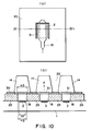
- Figure 1 is a sectional view of a liquid flow path of a conventional liquid ejecting head.
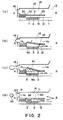
- Figure 2 is a schematic sectional view of example of a liquid ejecting head.
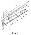
- Figure 3 is a partly broken perspective view of a liquid ejecting head.
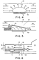
- Figure 4 is a schematic view of pressure propagation from a bubble in a conventional head.
- Figure 5 is a schematic view of pressure propagation from a bubble in a head.
- Figure 6 is a schematic view of a liquid flow.
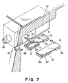
- Figure 7 depicts the essential portion of the liquid ejection head in the first embodiment of the present invention.
- Figure 8 is a schematic drawing for describing the principal operation of the liquid ejection head during the contraction-vanishment of the bubble.
- Figure 9 depicts the essential portion of the liquid ejection head in the second embodiment of the present invention.
- Figure 10 depicts the essential portion of the liquid ejection head in the third embodiment of the present invention.
- Figure 11 depicts the essential portion of the liquid ejection head in the fourth embodiment of the present invention.
- Figure 12 is a cross-sectional view of the liquid ejection head (second liquid passage) in the fourth embodiment of the present invention.
- Figure 13 depicts the essential portion of the liquid ejection head in the fifth embodiment of the present invention.
- Figure 14 depicts the essential portion of the liquid ejection head in the sixth embodiment of the present invention.
- Figure 15 depicts the essential portion of the liquid ejection head in the seventh embodiment of the present invention.
- Figure 16 depicts the essential portion of the liquid ejection head in the eighth embodiment of the present invention.
- Figure 17 depicts the essential portion of the liquid ejection head in the ninth embodiment of the present invention.
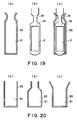
- Figure 18 depicts the moving member and the second liquid passage structure.
- Figure 19 depicts the moving member and the liquid passage structure.
- Figure 20 depicts various configurations of the moving member.
- Figure 21 is a longitudinal section of the liquid ejection head in accordance with the present invention.
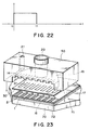
- Figure 22 is a diagram showing the form of the driving pulse.
- Figure 23 is an exploded perspective view of the liquid ejection head in accordance with the present invention.
- Figure 24 is an exploded perspective view of a liquid ejection head cartridge.
- Figure 25 is a perspective view of a liquid ejection apparatus, depicting the general structure thereof.
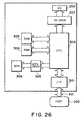
- Figure 26 is a block diagram of the apparatus illustrated in Figure 25.
- Figure 27 is a perspective view of a liquid ejection recording system.
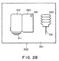
- Figure 28 is a schematic drawing of a head kit.
- Figure 2 is a schematic sectional view of a liquid ejecting head taken along a liquid flow path
- Figure 3 is a partly broken perspective view of the liquid ejecting head.
- This liquid ejecting head comprises a heat generating element 2 (a heat generating resistor of 40 ⁇ m x 105 ⁇ m in this embodiment) as the ejection energy generating element for supplying thermal energy to the liquid to eject the liquid, an element substrate 1 on which said heat generating element 2 is provided, and a liquid flow path 10 formed above the element substrate correspondingly to the heat generating element 2.
- the liquid flow path 10 is in fluid communication with a common liquid chamber 13 for supplying the liquid to a plurality of such liquid flow paths 10 which is in fluid communication with a plurality of the ejection outlets 18.
- a movable member or plate 31 in the form of a cantilever of an elastic material such as metal is provided faced to the heat generating element 2.
- One end of the movable member is fixed to a foundation (supporting member) 34 or the like provided by patterning of photosensitivity resin material on the wall of the liquid flow path 10 or the element substrate.
- the movable member 31 is so positioned that it has a fulcrum (fulcrum portion which is a fixed end) 33 in an upstream side with respect to a general flow of the liquid from the common liquid chamber 13 toward the ejection outlet 18 through the movable member 31 caused by the ejecting operation and that it has a free end (free end portion) 32 in a downstream side of the fulcrum 33.
- the movable member 31 is faced to the heat generating element 2 with a gap of 15 ⁇ m approx. as if it covers the heat generating element 2.
- a bubble generation region is constituted between the heat generating element and movable member.
- the type, configuration or position of the heat generating element or the movable member is not limited to the ones described above, but may be changed as long as the growth of the bubble and the propagation of the pressure can be controlled.
- the liquid flow path 10 is divided by the movable member 31 into a first liquid flow path 14 which is directly in communication with the ejection outlet 18 and a second liquid flow path 16 having the bubble generation region 11 and the liquid supply port 12.
- the movable member disposed faced to the bubble is displaced from the normal first position to the displaced second position on the basis of the pressure of the bubble generation or the bubble per se, and the displacing or displaced movable member 31 is effective to direct the pressure produced by the generation of the bubble and/or the growth of the bubble per se toward the ejection outlet 18 (downstream side).
- the movable member 31 is effective to direct, to the downstream (ejection outlet side), the pressure propagation directions V1-V4 of the bubble which otherwise are toward various directions. thus, the pressure propagations of bubble 40 are concentrated, so that the pressure of the bubble 40 is directly and efficiently contributable to the ejection.
- the growth direction per se of the bubble is directed downstream similarly to to the pressure propagation directions V1-V4, and grow more in the downstream side than in the upstream side.
- the growth direction per se of the bubble is controlled by the movable member, and the pressure propagation direction from the bubble is controlled thereby, so that the ejection efficiency, ejection force and ejection speed or the like are fundamentally improved.
- FIG 2 (a) shows a state before the energy such as electric energy is applied to the heat generating element 2, and therefore, no heat has yet been generated.
- the movable member 31 is so positioned as to be faced at least to the downstream portion of the bubble generated by the heat generation of the heat generating element.
- the liquid flow passage structure is such that the movable member 31 extends at least to the position downstream (downstream of a line passing through the center 3 of the area of the heat generating element and perpendicular to the length of the flow path) of the center 3 of the area of the heat generating element.
- FIG 2 (b) shows a state wherein the heat generation of heat generating element 2 occurs by the application of the electric energy to the heat generating element 2, and a part of of the liquid filled in the bubble generation region 11 is heated by the thus generated heat so that a bubble is generated through the film boiling.
- the movable member 31 is displaced from the first position to the second position by the pressure produced by the generation of the bubble 40 so as to guide the propagation of the pressure toward the ejection outlet.
- the free end 32 of the movable member 31 is disposed in the downstream side (ejection outlet side), and the fulcrum 33 is disposed in the upstream side (common liquid chamber side), so that at least a part of the movable member is faced to the downstream portion of the bubble, that is, the downstream portion of the heat generating element.
- FIG 2 shows a state in which the bubble 40 has further grown.
- the movable member 31 is displaced further.
- the generated bubble grows more downstream than upstream, and it expands greatly beyond a first position (broken line position) of the movable member.
- the bubble 40 is controlled so that it grows in the direction in which the pressure generated by the bubble 40 can easily escape or be released, and in which the bubble 40 easily shifts in volumetric terms. In other words, the growth of the bubble is uniformly directed toward the free end of the movable member. This also is thought to contribute to the improvement of the ejection efficiency.
- the movable member 31 gradually displaces, by which the pressure propagation direction of the bubble 40, the direction in which the volume movement is easy, namely, the growth direction of the bubble, are directed uniformly toward the ejection outlet, so that the ejection efficiency is increased.
- the movable member guides the bubble and the bubble generation pressure toward the ejection outlet, it hardly obstructs propagation and growth, and can efficiently control the propagation direction of the pressure and the growth direction of the bubble in accordance with the degree of the pressure.
- FIG. 2 shows a state wherein the bubble 40 contracts and disappears by the decrease of the pressure in the bubble, peculiar to the film boiling phenomenon.
- the movable member 31 having been displaced to the second position returns to the initial position (first position) of Figure 2, (a) by the restoring force provided by the spring property of the movable member per se and the negative pressure due to the contraction of the bubble.
- the liquid flows back from the common liquid chamber side as indicated by V D1 and V D2 and from the ejection outlet side as indicated by V C so as to compensate for the volume reduction of the bubble in the bubble generation region 11 and to compensate for the volume of the ejected liquid.
- the amount of the liquid from the ejection outlet side to the bubble collapse position and the amount of the liquid from the common liquid chamber thereinto are attributable to the flow resistances of the portion closer to the ejection outlet than the bubble generation region and the portion closer to the common liquid chamber.
- the meniscus retraction stops at the time when the movable member returns to the initial position upon the collapse of bubble, and thereafter, the supply of the liquid to fill a volume W2 is accomplished by the flow V D2 through the second flow path 16 (W1 is a volume of an upper side of the bubble volume W beyond the first position of the movable member 31, and W2 is a volume of a bubble generation region 11 side thereof).
- W1 is a volume of an upper side of the bubble volume W beyond the first position of the movable member 31
- W2 is a volume of a bubble generation region 11 side thereof.
- a half of the volume of the bubble volume W is the volume of the meniscus retraction, but according to this embodiment, only about one half (W1) is the volume of the meniscus retraction.
- liquid supply for the volume W2 is forced to be effected mainly from the upstream (V D2 ) of the second liquid flow path along the surface of the heat generating element side of the movable member 31 using the pressure upon the collapse of bubble, and therefore, more speedy refilling action is accomplished.
- the vibration of the meniscus is expanded with the result of the deterioration of the image quality.
- the flows of the liquid in the first liquid flow path 14 at the ejection outlet side and the ejection outlet side of the bubble generation region 11 are suppressed, so that the vibration of the meniscus is reduced.
- the high speed refilling is accomplished by the forced refilling to the bubble generation region through the liquid supply passage 12 of the second flow path 16 and by the suppression of the meniscus retraction and vibration. Therefore, the stabilization of ejection and high speed repeated ejections are accomplished, and when the embodiment is used in the field of recording, the improvement in the image quality and in the recording speed can be accomplished.
- the movable member provides the following effective function. It is a suppression of the propagation of the pressure to the upstream side (back wave) produced by the generation of the bubble.
- the pressure due to the common liquid chamber 13 side (upstream) of the bubble generated on the heat generating element 2 mostly has resulted in force which pushes the liquid back to the upstream side (back wave).
- the back wave deteriorates the refilling . of the liquid into the liquid flow path by the pressure at the upstream side, the resulting motion of the liquid and the resulting inertia force.
- these actions to the upstream side are suppressed by the movable member 31, so that the refilling performance is further improved.
- the second liquid flow path 16 has a liquid supply passage 12 having an internal wall substantially flush with the heat generating element 2 (the surface of the heat generating element is not greatly stepped down) at the upstream side of the heat generating element 2.
- the supply of the liquid to the surface of the heat generating element 2 and the bubble generation region 11 occurs along the surface of the movable member 31 at the position closer to the bubble generation region 11 as indicated by V D2 . Accordingly, stagnation of the liquid on the surface of the heat generating element 2 is suppressed, so that precipitation of the gas dissolved in the liquid is suppressed, and the residual bubbles not disappeared are removed without difficulty, and in addition, the heat accumulation in the liquid is not too much. Therefore, the stabilized bubble generation can be repeated at a high speed.
- the liquid supply passage 12 has a substantially flat internal wall, but this is not limiting, and the liquid supply passage is satisfactory if it has an internal wall with such a configuration smoothly extended from the surface of the heat generating element that the stagnation of the liquid occurs on the heat generating element, and eddy flow is not significantly caused in the supply of the liquid.
- the supply of the liquid into the bubble generation region may occur through a gap at a side portion of the movable member (slit 35) as indicated by V D1 .
- a large movable member covering the entirety of the bubble generation region (covering the surface of the heat generating element) may be used, as shown in Figure 2. then, the flow resistance for the liquid between the bubble generation region 11 and the region of the first liquid flow path 14 close to the ejection outlet is increased by the restoration of the movable member to the first position, so that the flow of the liquid to the bubble generation region 11 along V D1 can be suppressed.
- the positional relation between the free end 32 and the fulcrum 33 of the movable member 31 is such that the free end is at a downstream position of the fulcrum as indicated by 6 in the Figure, for example.
- the function and effect of guiding the pressure propagation direction and the direction of the growth of the bubble to the ejection outlet side or the like can be efficiently assured upon the bubble generation.
- the positional relation is effective to accomplish not only the function or effect relating to the ejection but also the reduction of the flow resistance through the liquid flow path 10 upon the supply of the liquid thus permitting the high speed refilling.
- the free end 32 of the movable member 3 is faced to a downstream position of the center 3 of the area which divides the heat generating element 2 into an upstream region and a downstream region (the line passing through the center (central portion) of the area of the heat generating element and perpendicular to a direction of the length of the liquid flow path).
- the movable member 31 receives the pressure and the bubble which are greatly contributable to the ejection of the liquid at the downstream side of the area center position 3 of the heat generating element, and it guides the force to the ejection outlet side, thus fundamentally improving the ejection efficiency or the ejection force.
- Figure 7 shows a first embodiment.
- A shows an upwardly displaced movable member although bubble is not shown
- B shows the movable member in the initial position (first position) wherein the bubble generation region 11 is substantially sealed relative to the ejection outlet 18.
- a foundation 34 is provided at each side, and between them, a liquid supply passage 12 is constituted.
- the liquid can be supplied along a surface of the movable member faced to the heat generating element side and from the liquid supply passage having a surface substantially flush with the surface of the heat generating element or smoothly continuous therewith.
- the movable member 31 When the movable member 31 is at the initial position(first position), the movable member 31 is close to or closely contacted to a downstream wall 36 disposed downstream of the heat generating element 2 and heat generating element side walls 37 disposed at the sides of the heat generating element, so that the ejection outlet 18 side of the bubble generation region 11 is substantially sealed.
- the pressure produced by the bubble at the time of the bubble generation and particularly the pressure downstream of the bubble can be concentrated on the free end side side of the movable member, without releasing the pressure.
- the movable member 31 returns to the first position, and the ejection outlet side of the bubble generation region 31 is substantially, sealed, and therefore, the meniscus retraction is suppressed, and the liquid supply to the heat generating element is carried out with the advantages described hereinbefore.
- the same advantageous effects can be provided as in the foregoing example.
- regulating means (wall 36 on the downstream side of the heat generation member, and walls along the heat generation member) are provided, which regulate the downward movement of the movable member so that when the movable member returns from the second position to the first position, the movable member is prevented from movable past the first position and entering the bubble generation region.
- the downward movement of the movable member past the first position that is, an excessive movement of the movable member is prevented; therefore, the durability of the movable member is further improved.
- Figure 8 is a schematic section of the liquid passage 10 of a liquid ejection head, at a point within the bubble generation region 11. It sequentially depicts the operation of the liquid ejection head.
- FIG 8 (a) depicts the state before the operation begins, in which the movable member is at the first position (initial position). In this state, the free end portion of the movable member is in contact with the aforementioned regulating means, being physically prevented from moving downward.
- FIG 8 depicts the state in which the movable member 31 is being moved by the pressure of the bubble developed by the heat from the heating member. Thereafter, as the bubble contracts, the movable member returns to the first position due to the negative pressure generated by the contraction of the bubble, and the elastic resilience of the movable member itself.
- the downward movement of the free end portion of the movable member is regulated by the aforementioned regulating means; the free end portion of the movable member is prevented from moving downward beyond the first position.
- the ejection outlet side of the heat generation region 11 is substantially sealed by the wall 36 which is located on the downstream side of the heat generating member and also functions as the regulating means, the walls 37 located along the heat generating member, and the movable member 31; therefore, the negative pressure in the bubble generation region is increased by the continuous contraction of the bubble ( Figure 8(d)). However, this negative pressure is canceled by the incoming recharging ink, preventing the deformation of the movable member.
- the foundation 34 for supporting and fixing the movable member 31 is provided at an upstream position away from the heat generating element 2, as shown in Figure 3 and Figure 7, and the foundation 34 has a width smaller than the liquid flow path 10 to supply the liquid to the liquid supply passage 12.
- the configuration of the foundation 34 is not limited to this structure, but may be anyone if smooth refilling is accomplished.
- the clearance between the movable member 31 and the clearance is 15 ⁇ m approx., but the distance may be changed as long as the pressure produced by the bubble generation is sufficiently propagated to the movable member.
- the moving member 31, more precisely, the free end portion thereof, is restrained or prevented from moving downward past the first position, by the regulating means such as the wall 36 on the downstream side of the heat generating member, or by the walls 37 along the lateral edges of the heat generating member; therefore, not only the efficiency at which the liquid is refilled is increased as described above, but also, the movement of the free end portion of the moving member is primarily confined to the area above the first position.
- Figure 9 is a schematic drawing of the liquid ejection head in this embodiment, depicting the structure of the liquid passage;
- Figure 9, (a) is a plan view depicting the positional relationship among a first liquid passage 14, a moving member 31, and a second liquid passage 16;
- Figure 9,(b) a sectional view thereof, at a line VA-VA' in Figure 9, (a);
- Figure 9, (c) is a sectional view at a line VB-VB' in Figure 9, (a).
- the second liquid passage 16 is provided with a narrow portion or throat 19.
- This narrow portion 19 is located on the upstream side of the heat generating member 2, forming a chamber structure (bubble generation chamber) capable of preventing the pressure generated by the bubble from escaping through the second liquid passage 16.
- the narrow portion of the liquid passage must be structured so that the cross-section thereof does not becomes excessively small, in consideration of the efficiency at which the liquid refills the liquid passage from which the liquid has been ejected.
- the major portion of the liquid to be ejected comes from the first liquid passage 14; the liquid within the second liquid passage 16 in which the heating member 2 is disposed is consumed only by a small amount. Accordingly, the liquid has to be refilled into the bubble generation region of the second liquid passage 16 only by the amount consumed by the bubble generation. Therefore, the distance between the lateral walls of the narrow portion 9 can be rendered extremely small, for example, from several microns to ten-odd microns, so that it becomes possible to concentrate the pressure from the growing bubble generated in the second liquid passage 16 toward the moving member 31, allowing only a small portion of it to dissipate into the surrounding area. In other words, the moving member 31 makes it possible to use the major portion of this pressure as the ejection pressure; therefore, a better ejection efficiency and a stronger ejection pressure can be obtained.
- the configuration of the second liquid passage 16 is not limited to the one described above. That is, any configuration is acceptable as long as it can allow the pressure from the bubble growth to be effectively directed toward the moving member.
- the width of the heating member 2 is designated by a reference H1; the width of the second liquid passage 2, by a reference H2; and the width of the moving member 31 is designated by a reference H3.
- Figure 10 (a) is a plan view for describing the positional relationship among the aforementioned first liquid passage 14, moving member 31, and second liquid passage 16, and Figure 10, (b) is a sectional view thereof along a line IV-IV' in Figure 10, (a).
- the natural position of the moving member (that is, the position at which the moving member 31 is not in action) is designated as the first position.
- the moving member 31 When the moving member 31 is at the first position, at least a portion (a part of the side portion and a part of the free end in this embodiment) of the edge of the moving member 31 is in contact with the liquid passage walls 23 which form the second liquid passage 16. Therefore, when the moving member having moved as indicated by an arrow mark A from the natural (initial) position returns to the natural (initial) position, it does not move into the second liquid passage 16 because it is blocked by the liquid passage walls 23. Further, in this embodiment, the moving member 31 is rendered wider than the heater. In other words, the relationship among the width H1 of the heating member 2, the width H2 of the second liquid passage 16, and the width H3 of the moving member 31 is: H3 > H2
- the returning movement of the moving member to the initial position is stabilized by satisfying the above relationships, making it possible to maintain a far more stable state of liquid ejection compared to the conventional system. As a result, it is possible to obtain a liquid ejection head which is far superior to the conventional one in ejection efficiency and durability.
- FIGS 11 and 12 depict the fourth embodiment of the present invention.
- Figure 11 (a) is a plan view depicting the positional relationship among the moving member 31, the second liquid passage 16, and the heating member 2.
- Figure 11, (b) is a sectional view thereof, at a line A-A illustrated in Figure 11, (a), wherein the moving member 31 is at the initial position.
- Figure 12 is a longitudinal sectional view taken along a line B-B illustrated in Figure 11, (a), and depicts the area from the position of the ejection orifice to the common liquid chamber.
- a second liquid flow path 16 for the bubble generation is provided on the element substrate 1 which is provided with a heat generating element 2 for supplying thermal energy for generating the bubble in the liquid, and a first liquid flow path 14 for the ejection liquid in direct communication with the ejection outlet 18 is formed thereabove.
- the upstream side of the first liquid flow path is in fluid communication with a first common liquid chamber 15 for supplying the ejection liquid into a plurality of first liquid flow paths
- the upstream side of the second liquid flow path is in fluid communication with the second common liquid chamber for supplying the bubble generation liquid to a plurality of second liquid flow paths.
- the number of the common liquid chambers may be one.
- first and second liquid flow paths there is a separation wall 30 of an elastic material such as metal so that the first flow path and the second flow path are separated.
- the first liquid flow path 14 and the second liquid flow path 16 are preferably isolated by the partition wall. however, when the mixing to a certain extent is permissible, the complete isolation is not inevitable.
- a portion of the partition wall in the upward projection space of the heat generating element is in the form of a cantilever movable member 31, formed by slits 35, having a fulcrum 33 at the common liquid chamber (15 17) side and free end at the ejection outlet side (downstream with respect to the general flow of the liquid).
- the movable member 31 is faced to the surface, and therefore, it operates to open toward the ejection outlet side of the first liquid flow path upon the bubble generation of the bubble generation liquid (direction of the arrow in the Figure).
- a partition wall 30 is disposed, with a space for constituting a second liquid flow path, above an element substrate 1 provided with a heat generating resistor portion as the heat generating element 2 and wiring electrodes 5 for applying an electric signal to the heat generating resistor portion.
- the structure of the moving member 31 in this embodiment is such that when the moving member 31 is at the initial position, both lateral edges of the moving member 31, and the entire edge of the free end portion, are in contact with the walls of the second liquid passage, rendering the bubble generation region 11 of the second liquid passage 16 substantially sealed from the first liquid passage 14.
- the downward movement of the moving member 31 is prevented by all of the edges.
- the bending stress which occurs at the supporting point is more effectively confined to a single direction. Consequently, the durability of the moving member is improved.
- liquid ejection head in which the partitioning wall, a part of which constitutes the moving member, is extended through the common liquid chamber to partition the common liquid chamber into two common liquid chambers 15 and 17, different liquids, for example, liquid to be primarily elected, and liquid for primarily generating the bubble, can be supplied to the first liquid passage 14 and the second liquid passage 16, respectively.
- liquid which is difficult to boil, liquid which is susceptible to heat, or the like liquid can be ejected in a preferable manner.
- the moving member of this embodiment when the moving member of this embodiment is at the initial position, the first and second liquid passages 14 and 16 are substantially sealed from each other. In other words, the liquid is prevented from moving between the two liquid passages; therefore, the mutual diffusion of the two different liquids, which might occur when the liquid ejection head is not in action, can be prevented.
- the ejection liquid and the bubble generation liquid may be separated, and the ejection liquid is ejected by the pressure produced in the bubble generation liquid. Accordingly, a high viscosity liquid such as polyethylene glycol or the like with which bubble generation and therefore ejection force is not sufficient by heat application, and which has not been ejected in good order, can be ejected. for example, this liquid is supplied into the first liquid flow path, and liquid with which the bubble generation is in good order is supplied into the second path as the bubble generation liquid.
- An example of the bubble generation liquid a mixture liquid (1 - 2 cP approx.) of the anol and water (4:6). by doing so, the ejection liquid can be properly ejected.
- the bubble generation liquid a liquid with which the deposition such as kogation does not remain on the surface of the heat generating element even upon the heat application, the bubble generation is stabilized to assure the proper ejections.
- liquid which is not durable against heat is ejectable.
- a liquid is supplied in the first liquid flow path as the ejection liquid, and a liquid which is not easily altered in the property by the heat and with which the bubble generation is in good order, is supplied in the second liquid flow path. by doing so, the liquid can be ejected without thermal damage and with high ejection efficiency and with high ejection pressure.
- Figure 13 is a schematic cross-sectional view of the liquid ejection head in this embodiment, and depicts the structure thereof;
- Figure 13 (a) depicts the movement of the movable member, which is triggered as a driving pulse is applied; and
- Figure 13, (b) depicts the state in which the driving pulse was turned off and the movable member has returned to the natural position from the position to which it had moved.
- the cross-section of the movable member 31 is shaped like an inverted trapezoid. Further, the edge of the partition wall 30, which faces the slit 35, is slanted to match the cross-section of the movable member 31.
- the width 31a of the movable member 31, on the side of the second liquid passage 15, is less than the width 31b of the movable member 31, on the side of the first liquid passage 14.
- the width 31b of the movable member 31, on the side of the first liquid passage 14 is less than the distance 35b between the opposing lateral edges of the partition wall 30, on the side of the first liquid passage 14, and is greater than the distance 35a between the opposing lateral edges of the partition wall 30, on the side of the second liquid passage 16: 35b ⁇ 35a.
- the movable member As the movable member returns to the initial position, it tends to move downward past the initial position due to the negative pressure within the second liquid passage and the elastic resiliency of the movable member itself, but in this embodiment, the slanted lateral surfaces of the movable member and the corresponding slanted surfaces of the partition wall 30 come in contact with each other, regulating the downward movement of the movable member; the downward movement on the movable member past the initial position is confined within a range equivalent to the width of the movable member 31. Therefore, the durability of the movable member is improved even though the structure of this embodiment is such that there is no specific stopper provided for the free end of the movable member.
- the invasion of the movable member 31 into the second liquid passage 14 is prevented by the partition wall 30 itself; therefore, the manufacturing steps can be simplified.
- Figure 14 is a schematic cross-section of the liquid passage of the liquid ejection head in this embodiment, and depicts its structure;
- Figure 14, (a) depicts the state in which the movable member is ready to move into the first liquid passage as a driving pulse is applied to the heating member 2;
- Figure 14, (b) depicts the state in which the driving pulse was turned off and the movable member has returned to the first position from the position to which it had moved.
- the configuration of the movable member in this embodiment is such that it is flat on the surface, on the side of the first liquid passage 14, and has a projection, on the surface on the side of the second liquid passage 16. The height of this projection is no greater than the height H9 of the partition wall 23.
- the movable member 31 tends to move into the second liquid passage 16, due to the negative pressure generated by the vanishing bubble and the elastic resilience of the movable member itself, but its movement into the second liquid passage 10 is regulated by the projection formed on the movable member 31; the downward movement of the movable member 31 past the first position is confined within the range equivalent to the thickness of the movable member itself ( Figure 14, (b)).
- Figure 15 is a schematic, longitudinal section of the liquid passage of the liquid ejection head in this embodiment, and depicts its structure. This drawing depicts the state in which the movable member 31 is moved by the bubble, which was generated in the liquid within the second liquid passage by the heat generated by the heater 2.
- the basic structure of the liquid ejection head in this embodiment is the same as that in the fourth embodiment, except that the free end 32 of the movable member 31 in this embodiment is extended beyond the corresponding end of the heat generating member 2 in the direction of the ejection orifice, and that plural projections are provided on the liquid passage wall 23 constituting a part of the bottom surface of the first liquid passage 14, in the area in which the free end portion of the movable member 31 makes contact with the bottom surface of the first liquid passage 14.
- These projections 14 prevent the movable member 31, which comes in contact with the liquid passage wall 23, from sticking to the liquid passage wall 23.
- the location where these projections 24 are positioned is not limited to the area correspondent to the free end portion of the movable member 31; other areas are acceptable. Obviously, they may be provided on the movable member 31 itself.
- the liquid passage ceiling level above the free end portion of the movable member 31 is raised higher than the liquid ceiling level above the supporting portion. It should be noted here that the liquid passage configuration described above is not limited to this embodiment; the application of this configuration to other embodiments similarly improves the durability of the movable member.
- Figure 16 is a schematic plan view of the liquid passages of the liquid ejection head in this embodiment, and depicts their structures.
- a reference numeral 2 designates a heat generating member
- a reference numeral 14 a second liquid passage
- a reference numeral 23 a liquid passage wall
- a reference numeral 24 designates a projection.
- plural projections 24 are provided on the liquid passage wall 23 constituting the bottom surface of the first liquid passage 14, in the area with which the free end portion of the movable member 31 makes contact.
- the configuration of the second liquid passage 16 is affected by the liquid passage wall 23; a narrow portion is formed. Further, a liquid passage wall 19 is partially cut away, and a passage 25 is provided to connect the adjacent second liquid passages 16 at their downstream side ends.
- a partition wall (Ni plate) 30, a part of which constitutes the movable member 31, is laminated onto the liquid passage wall 23 patterned as described above, covering the second liquid passage 16 in such a manner that the tip of the movable member 31 makes contact with the liquid passage wall 23.
- Figure 17 is a schematic plan view of the liquid passage of the liquid ejection head in this embodiment, and depicts its structure. Also in this embodiment, a passage 25 connecting the adjacent second liquid passages 16 as described in the eighth embodiment is provided though it is slightly different; the passage 25 in this embodiment is made to run in zigzag. Therefore, the length of the connecting passage 25 between the adjacent second liquid passages 16 becomes longer, rendering the liquid ejection head more resistant to cross-talk.
- the movement (downward displacement) of the free end of the movable member from the first position into the bubble generation region (toward the heat generating member past the first position) is regulated; therefore, the stress which occurs in the supporting portion of the movable member is rendered unidirectional. Consequently, the durability of the movable member is drastically improved.
- the meniscus vibration is suppressed to a minimum, and therefore, the negative pressure, which is generated in the bubble generation region as the bubble vanishes, is more effectively utilized to recharge the liquid passage with liquid. As a result, the liquid passages can be recharged at a higher frequency.
- the movable member when the movable member is at the first position, it contacts the regulating means, or maintains a slight gap therefrom, that is, there is no gap in practical terms between the movable member and the regulating means; therefore, the generated bubble does not escape through the gap (slit) between the two components, fully acting on the movable member. Accordingly, it is possible to produce a liquid ejection head with a higher ejection efficiency and a higher ejection force.
- both lateral edge portions of the movable member, and the free end edge portion of the movable member are placed in contact with the corresponding walls of the second liquid passage.
- This arrangement is extremely useful when it is necessary to fill the first and second liquid passages each with a different liquid, since the downward movement of the movable member does not mix the liquid in the first liquid passage with the liquid in the second liquid passage, and the two liquids are prevented from diffusing each other when the liquid ejection head is not in action.
- the movable member is prevented from sticking to the liquid passage wall, by placing plural projections on the bottom surface of the first liquid passage, in the area with which the movable member make contact.
- the first liquid liquid to be ejected
- the second liquid bubble generation liquid
- the liquid to be ejected is prevented from being scorched and sticking to the heater.
- the movable member is prevented from sticking to the partition wall between the first and second liquid passages. Therefore, it is possible to provide a liquid ejection head, which is capable of stable ejection, and in which two liquid passages are given a different functions.
- Figure 18 is a sectional view taken along the length of the flow path of the liquid ejecting head according to the embodiment.
- grooves for constituting the first liquid flow paths 14 are formed in grooved member 50 on a partition wall 30.
- the height of the flow path ceiling adjacent the free end 32 position of the movable member is greater to permit larger operation angle ⁇ of the movable member.
- the operation range of the movable member is determined in consideration of the structure of the liquid flow path, the durability of the movable member and the bubble generation power or the like. It is desirable that it moves in the angle range wide enough to include the angle of the position of the ejection outlet.
- the displaced level of the free end of the movable member is made higher than the diameter of the ejection outlet, by which sufficient ejection pressure is transmitted.
- a height of the liquid flow path ceiling at the fulcrum 33 position of the movable member is lower than that of the liquid flow path ceiling at the free end 32 position of the movable member, so that the release of the pressure wave to the upstream side due to the displacement of the movable member can be further effectively prevented.
- Figure 19 is an illustration of a positional relation between the above-described movable member 31 and second liquid flow path 16, and (a) is a view of the movable member 31 position of the partition wall 30 as seen from the above, and (b) is a view of the second liquid flow path 16 seen from the above without partition wall 30.
- Figure 19 (c) is a schematic view of the positional relation between the movable member 6 and the second liquid flow path 16 wherein the elements are overlaid.
- the bottom is a front side having the ejection outlets.
- the second liquid flow path 16 of this embodiment has a throat portion 19 upstream of the heat generating element 2 with respect to a general flow of the liquid from the second common liquid chamber side to the ejection outlet through the heat generating element position, the movable member position along the first flow path, so as to provide a chamber (bubble generation chamber) effective to suppress easy release, toward the upstream side, of the pressure produced upon the bubble generation in the second liquid flow path 16.
- the lateral sides of the movable member 31 cover respective parts of the walls constituting the second liquid flow path so that the falling of the movable member 31 into the second liquid flow path is prevented.
- the above-described separation between the ejection liquid and the bubble generation liquid is further enhanced.
- the release of the bubble through the slit can be suppressed so that ejection pressure and ejection efficiency are further increased.
- the above-described effect of the refilling from the upstream side by the pressure upon the collapse of bubble can be further enhanced.
- a part of of the bubble generated in the bubble generation region of the second liquid flow path 4 with the displacement of the movable member 6 to the first liquid flow path 14 side extends into the first liquid flow path 14 side.
- the height of the second flow path 16 is preferably lower than the height of the maximum bubble, more particularly, the second liquid flow path is preferably several ⁇ m - 30 ⁇ m, for example. In this embodiment, the height is 15 ⁇ m.
- Figure 20 shows another example of the movable member 31, wherein reference numeral 35 designates a slit formed in the partition wall, and the slit is effective to provide the movable member 31.
- the movable member has a rectangular configuration, and in (b), it is narrower in the fulcrum side to permit increased mobility of the movable member, and in (c), it has a wider fulcrum side to enhance the durability of the movable member.
- the configuration narrowed and arcuated at the fulcrum side is desirable if it does not enter the second liquid flow path side, and motion is easy with high durability.
- the plate or film movable member 31 and the separation wall 5 having this movable member was made of a nickel having a thickness of 5 ⁇ m, but this is not limited to this example, but it may be any if it has anti-solvent property against the bubble generation liquid and the ejection liquid, and if the elasticity is enough to permit the operation of the movable member, and if the required fine slit can be formed.
- the materials for the movable member include durable materials such as metal such as silver, nickel, gold, iron, titanium, aluminum, platinum, tantalum, stainless steel, phosphor bronze or the like, alloy thereof, or resin material having nytril group such as acrylonitrile, butadiene, stylene or the like, resin material having amide group such as polyamide or the like, resin material having carboxyl such as polycarbonate or the like, resin material having aldehyde group such as polyacetal or the like, resin material having sulfon group such as polysulfone, resin material such as liquid crystal polymer or the like, or chemical compound thereof; or materials having durability against the ink, such as metal such as gold, tungsten, tantalum, nickel, stainless steel, titanium, alloy thereof, materials coated with such metal, resin material having amide group such as polyamide, resin material having aldehyde group such as polyacetal, resin material having ketone group such as polyetheretherketone, resin material having imide group such as polyimi
- partition or division wall include resin material having high heat-resistive, high anti-solvent property and high molding property, more particularly recent engineering plastic resin materials such as polyethylene, polypropylene, polyamide, polyethylene terephthalate, melamine resin material, phenolic resin, epoxy resin material, polybutadiene, polyurethane, polyetheretherketone, polyether sulfone, polyallylate, polyimide, poly--sulfone, liquid crystal polymer (LCP), or chemical compound thereof, or metal such as silicon dioxide, silicon nitride, nickel, gold, stainless steel, alloy thereof, chemical compound thereof, or materials coated with titanium or gold.
- engineering plastic resin materials such as polyethylene, polypropylene, polyamide, polyethylene terephthalate, melamine resin material, phenolic resin, epoxy resin material, polybutadiene, polyurethane, polyetheretherketone, polyether sulfone, polyallylate, polyimide, poly--sulfone, liquid crystal polymer (LCP), or chemical compound
- the thickness of the separation wall is determined depending on the used, material and configuration from the standpoint of sufficient strength as the wall and sufficient operativity as the movable member, and generally, 0.5 ⁇ m - 10 ⁇ m approx. is desirable.
- the width of the slit 35 for providing the movable member 31 is 2 ⁇ m in the embodiments.
- the gap is determined so as to form a meniscus between the liquids, thus avoiding mixture therebetween.
- the bubble generation liquid has a viscosity about 2 cP
- the ejection liquid has a viscosity not less than 100 cP
- 5 ⁇ m approx. slit is enough to avoid the liquid mixture, but not more than 3 ⁇ m is desirable.
- the movable member When the ejection liquid and the bubble generation liquid are separated, the movable member functions as a partition therebetween. However, a small amount of the bubble generation liquid is mixed into the ejection liquid. In the case of liquid ejection for printing, the percentage of the mixing is practically of no problem, if the percentage is less than 20 %. The percentage of the mixing can be controlled in the present invention by properly selecting the viscosities of the ejection liquid and the bubble generation liquid.
- the percentage When the percentage is desired to be small, it can be reduced to 5 %, for example, by using 5 CPS or lower fro the bubble generation liquid and 20 CPS or lower for the ejection liquid.
- the movable member has a thickness of ⁇ m order as preferable thickness, and a movable member having a thickness of cm order is not used in usual cases.
- a slit is formed in the movable member having a thickness of ⁇ m order, and the slit has the width (W ⁇ m) of the order of the thickness of the movable member, it is desirable to consider the variations in the manufacturing.
- the relation between the slit width and the thickness is preferably as follows in consideration of the variation in the manufacturing to stably suppress the liquid mixture between the bubble generation liquid and the ejection liquid.
- the bubble generation liquid has a viscosity not more than 3cp, and a high viscous ink (5 cp, 10 cp or the like) is used as the ejection liquid, the mixture of the 2 liquids can be suppressed for a long term if W/t ⁇ 1 is satisfied.
- the slit providing the "substantial sealing”, preferably has several microns width, since the liquid mixture prevention is assured.
- Figure 21 is a longitudinal section of the liquid ejecting head according to an embodiment of the present invention.
- a grooved member 50 is mounted, the member 50 having second liquid flow paths 16, separation walls 30, first liquid flow paths 14 and grooves for constituting the first liquid flow path.
- the element substrate 1 has, as shown in Figure 12, patterned wiring electrode (0.2 - 1.0 ⁇ m thick) of aluminum or the like and patterned electric resistance layer 105 (0.01 - 0.2 ⁇ m thick) of hafnium boride (HfB 2 ), tantalum nitride(TaN), tantalum aluminum(TaAl) or the like constituting the heat generating element on a silicon oxide film or silicon nitride film 106 for insulation and heat accumulation, which in turn is on the substrate 107 of silicon or the like.
- a voltage is applied to the resistance layer 105 through the two wiring electrodes 104 to flow a current through the resistance layer to effect heat generation.
- a protection layer of silicon oxide, silicon nitride or the like of 0.1 - 2.0 ⁇ m thick is provided on the resistance layer, and in addition, an anti-cavitation layer of tantalum or the like (0.1 - 0.6 ⁇ m thick) is formed thereon to protect the resistance layer 105 from various liquid such as ink.
- metal material such as tantalum (Ta) or the like is used as the anti-cavitation layer.
- the protection layer may be omitted depending on the combination of liquid, liquid flow path structure and resistance material. one of such examples is shown in Figure 19, (b).
- the material of the resistance layer not requiring the protection layer includes, for example, iridium - tantalum-aluminum alloy or the like.
- the structure of the heat generating element in the foregoing embodiments may include only the resistance layer(heat generation portion) or may include a protection layer for protecting the resistance layer.
- the heat generating element has a heat generation portion having the resistance layer which generates heat in response to the electric signal.
- heat generation portion may be in the form of a photothermal transducer which generates heat upon receiving light such as laser, or the one which generates heat upon receiving high frequency wave.
- function elements such as a transistor, a diode, a latch, a shift register and so on for selective driving the electrothermal transducer element may also be integrally built in, in addition to the resistance layer 105 constituting the heat generation portion and the electrothermal transducer constituted by the wiring electrode 104 for supplying the electric signal to the resistance layer.
- the resistance layer 105 is supplied through the wiring electrode 104 with rectangular pulses as shown in Figure 22 to cause instantaneous heat generation in the resistance layer 105 between the wiring electrode.
- the applied energy has a voltage of 24V, a pulse width of 7 ⁇ sec, a current of 150mA and a frequency of 6kHz to drive the heat generating element, by which the liquid ink is ejected through the ejection outlet through the process described hereinbefore.
- the driving signal conditions are not limited to this, but may be any if the bubble generation liquid is properly capable of bubble generation.
- the liquid can be ejected at higher ejection force or ejection efficiency than the conventional liquid ejecting head.
- the same liquid is used for the bubble generation liquid and the ejection liquid, it is possible that the liquid is not deteriorated, and that deposition on the heat generating element due to heating can be reduced. Therefore, a reversible state change is accomplished by repeating the gassification and condensation. So, various liquids are usable, if the liquid is the one not deteriorating the liquid flow passage, movable member or separation wall or the like.
- the one having the ingredient as used in conventional bubble jet device can be used as a recording liquid.
- the bubble generation liquid having the above-described property includes: methanol, ethanol, n-propyl alcohol, isopropyl alcohol, n- n-hexane, n-heptane, n-octane, toluene, xylene, methylene dichloride, trichloroethylene, Freon TF, Freon BF, ethyl ether, dioxane, cyclohexane, methyl acetate, ethyl acetate, acetone, methyl ethyl ketone, water, or the like, and a mixture thereof.
- the ejection liquid various liquids are usable without paying attention to the degree of bubble generation property or thermal property.
- the ejection liquid by itself or by reaction with the bubble generation liquid, does not impede the ejection, the bubble generation or the operation of the movable member or the like.
- the recording ejection liquid high viscous ink or the like is usable.
- pharmaceuticals and perfume or the like having a nature easily deteriorated by heat is usable.
- the ink of the following ingredient was used as the recording liquid usable for both of the ejection liquid and the bubble generation liquid, and the recording operation was carried out. Since the ejection speed of the ink is increased, the shot accuracy of the liquid droplets is improved, and therefore, highly desirable images were recorded.
- Dye ink viscosity of 2cp C.I. food black 2
- Bubble generation liquid 1 Ethanol 40 wt. % Water 60 wt. %
- Bubble generation liquid 2 Water 100 wt. %
- Bubble generation liquid 3 Isopropyl alcoholic 10 wt. % Water 90 wt. %
- Ejection liquid 1 (Pigment ink approx. 15 cp) Carbon black 5 wt.
- the ejection speed is low, and therefore, the variation in the ejection direction is expanded on the recording paper with the result of poor shot accuracy. Additionally, variation of ejection amount occurs due to the ejection instability, thus preventing the recording of high quality image.
- the use of the bubble generation liquid permits sufficient and stabilized generation of the bubble. Thus, the improvement in the shot accuracy of the liquid droplet and the stabilization of the ink ejection amount can be accomplished, thus improving the recorded image quality remarkably.
- Figure 23 is an exploded perspective view of the twin passage liquid ejection head in accordance with the present invention, and depicts its general structure.
- the aforementioned element substrate 1 is disposed on a supporting member 70 of aluminum or the like.
- the wall 72 of the second liquid passage and the wall 71 of the second common liquid chamber 17 are disposed on this substrate 1.
- the partition wall 30, a part of which constitutes a moving member 31, is placed on top of them.
- a grooved member 50 is disposed, which comprises: plural grooves constituting first liquid passages 14; a first common liquid chamber 15; a supply passage 20 for supplying the first common liquid chamber 15 with first liquid; and a supply passage 21 for supplying the second common liquid chamber 17 with second liquid.
- Figure 24 is a schematic exploded perspective view of a liquid ejection head cartridge including the above-described liquid ejecting head, and the liquid ejection head cartridge comprises generally a liquid ejecting head portion 200 and a liquid container 80.
- the liquid ejecting head portion 200 comprises an element substrate 1, a separation wall 30, a grooved member 50, a confining spring 70, liquid supply member 90 and a supporting member 70.
- the element substrate 1 is provided with a plurality of heat generating resistors for supplying heat to the bubble generation liquid, as described hereinbefore.
- a bubble generation liquid passage is formed between the element substrate 1 and the separation wall 30 having the movable wall.
- the confining spring 70 functions to urge the grooved member 50 to the element substrate 1, and is effective to properly integrate the element substrate 1, separation wall 30, grooved and the supporting member 70 which will be described hereinafter.
- Supporting member 70 functions to support an element substrate 1 or the like, and the supporting member 70 has thereon a circuit board 71, connected to the element substrate 1, for supplying the electric signal thereto, and contact pads 72 for electric signal transfer between the device side when the cartridge is mounted on the apparatus.
- the liquid container 90 contains the ejection liquid such as ink to be supplied to the liquid ejecting head and the bubble generation liquid for bubble generation, separately.
- the outside of the liquid container 90 is provided with a positioning portion 94 for mounting a connecting member for connecting the liquid ejecting head with the liquid container and a fixed shaft 95 for fixing the connection portion.
- the ejection liquid is supplied to the ejection liquid supply passage 81 of a liquid supply member 80 through a supply passage 81 of the connecting member from the ejection liquid supply passage 92 of the liquid container, and is supplied to a first common liquid chamber through the ejection liquid supply passage 83, supply and 21 of the members.
- the bubble generation liquid is similarly supplied to the bubble generation liquid supply passage 82 of the liquid supply member 80 through the supply passage of the connecting member from the supply passage 93 of the liquid container, and is supplied to the second liquid chamber through the bubble generation liquid supply passage 84, 71, 22 of the members.
- the liquid containers may be supplied with the respective liquids.
- the liquid container is desirably provided with a liquid injection port.
- the liquid ejecting head and liquid container may be unseparably integral, or may be separable.
- FIG 25 is a schematic illustration of a liquid ejecting device used with the above-described liquid ejecting head.
- the ejection liquid is ink
- the apparatus is an ink ejection recording apparatus.
- the liquid ejecting device comprises a carriage HC to which the head cartridge comprising a liquid container portion 90 and liquid ejecting head portion 200 which are detachably connectable with each other, is mountable.
- the carriage HC is reciprocable in a direction of width of the recording material 150 such as a recording sheet or the like fed by a recording material transporting means.
- the recording liquid is ejected to the recording material from the liquid ejecting head in response to the signal.
- the liquid ejecting apparatus of this embodiment comprises a motor 111 as a driving source for driving the recording material transporting means and the carriage, gears 112, 113 for transmitting the power from the driving source to the carriage, and carriage shaft 115 and so on.
- Figure 26 is a block diagram for describing the general operation of an ink ejection recording apparatus which employs the liquid ejection method, and the liquid ejection head, in accordance with the present invention.
- the recording apparatus receives printing data in the form of a control signal from a host computer 300.
- the printing data is temporarily stored in an input interface 301 of the printing apparatus, and at the same time, is converted into processable data to be inputted to a CPU 302, which doubles as means for supplying a head driving signal.
- the CPU 302 processes the aforementioned data inputted to the CPU 302, into printable data (image data), by processing them with the use of peripheral units such as RAMs 304 or the like, following control programs stored in an ROM 303.
- the CPU 302 in order to record the image data onto an appropriate spot on a recording sheet, the CPU 302 generates driving data for driving a driving motor which moves the recording sheet and the recording head in synchronism with the image data.
- the image data and the motor driving data are transmitted to a head 200 and a driving motor 306 through a head driver 307 and a motor driver 305, respectively, which are controlled with the proper timings for forming an image.
- recording medium to which liquid such as ink is adhered, and which is usable with a recording apparatus such as the one described above, the following can be listed; various sheets of paper; OHP sheets; plastic material used for forming compact disks, ornamental plates, or the like; fabric; metallic material such as aluminum, copper, or the like; leather material such as cow hide, pig hide, synthetic leather, or the like; lumber material such as solid wood, plywood, and the like; bamboo material; ceramic material such as tile; and material such as sponge which has a three dimensional structure.
- the aforementioned recording apparatus includes a printing apparatus for various sheets of paper or OHP sheet, a recording apparatus for plastic material such as plastic material used for forming a compact disk or the like, a recording apparatus for metallic plate or the like, a recording apparatus for leather material, a recording apparatus for lumber, a recording apparatus for ceramic material, a recording apparatus for three dimensional recording medium such as sponge or the like, a textile printing apparatus for recording images on fabric, and the like recording apparatuses.
- a printing apparatus for various sheets of paper or OHP sheet a recording apparatus for plastic material such as plastic material used for forming a compact disk or the like, a recording apparatus for metallic plate or the like, a recording apparatus for leather material, a recording apparatus for lumber, a recording apparatus for ceramic material, a recording apparatus for three dimensional recording medium such as sponge or the like, a textile printing apparatus for recording images on fabric, and the like recording apparatuses.
- any liquid is usable as long as it is compatible with the employed recording medium, and the recording conditions.
- FIG 31 is a schematic perspective view of an ink jet recording system employing the aforementioned liquid ejection head 201 in accordance with the present invention, and depicts its general structure.
- the liquid ejection head in this embodiment is a full-line type head, which comprises plural ejection orifices aligned with a density of 360 dpi so as to cover the entire recordable range of the recording medium 150. It comprises four heads, which are correspondent to four colors; yellow (Y), magenta (M), cyan (C) and black (Bk). These four heads are fixedly supported by a holder 1202, in parallel to each other and with predetermined intervals.
- These heads are driven in response to the signals supplied from a head driver 307, which constitutes means for supplying a driving signal to each head.
- Each of the four color inks (Y, M, C and Bk) is supplied to a correspondent head from an ink container 204a, 204b, 205c or 204d.
- a reference numeral 204e designates a bubble generation liquid container from which the bubble generation liquid is delivered to each head.
- a head cap 203a, 203b, 203c or 203d is disposed, which contains an ink absorbing member composed of sponge or the like. They cover the ejection orifices of the corresponding heads, protecting the heads, and also maintaining the head performance, during a non-recording period.
- a reference numeral 206 designates a conveyer belt, which constitutes means for conveying the various recording medium such as those described in the preceding embodiments.
- the conveyer belt 206 is routed through a predetermined path by various rollers, and is driven by a driver roller connected to a motor driver 305.
- the ink jet recording system in this embodiment comprises a pre-printing processing apparatus 251 and a postprinting processing apparatus 252, which are disposed on the upstream and downstream sides, respectively, of the ink jet recording apparatus, along the recording medium conveyance path.
- These processing apparatuses 251 and 252 process the recording medium in various manners before or after recording is made, respectively.
- the pre-printing process and the postprinting process vary depending on the type of recording medium, or the type of ink.
- recording medium composed of metallic material, plastic material, ceramic material or the like
- the recording medium is exposed to ultraviolet rays and ozone before printing, activating its surface.
- a pre-processing may be effected wherein alkali property substance, water soluble property substance, composition polymeric, water soluble property metal salt, urea, or thiourea is applied to the textile.
- the pre-processing is not limited to this, and it may be the one to provide the recording material with the proper temperature.
- the post-processing is a process for imparting, to the recording material having received the ink, a heat treatment, ultraviolet radiation projection to promote the fixing of the ink, or a cleaning for removing the process material used for the pre-treatment and remaining because of no reaction.
- the head is a full line head, but the present invention is of course applicable to a serial type wherein the head is moved along a width of the recording material.
- FIG. 28 is a schematic view of such a head kit.
- This head kit is in the form of a head kit package 501, and contains: a head 510 in accordance with the present invention, which comprises an ink ejection section 511 for ejecting ink; an ink container 510, that is, a liquid container which is separable, or nonseparable, from the head; and ink filling means 530, which holds the ink to be filled into the ink container 520.
- the tip 530 in the form of a hypodermic needle or the like
- the tip 530 of the ink filling means is inserted into an air vent 521 of the ink container, the junction between the ink container and the head, or a hole drilled through the ink container wall, and the ink within the ink filling means is filled into the ink container through this tip 531.
- the ink container When the liquid ejection head, the ink container, the ink filling means, and the like are available in the form of a kit contained in the kit package, the ink can be easily filled into the ink depleted ink container as described above; therefore, recording can be quickly restarted.
- the head kit contains the ink filling means.
- the kit may contain an exchangeable type ink container filled with the ink, and a head.
- the head kit may contain means for filling the bubble generation liquid into the bubble generation liquid container, in addition to the printing ink refilling means.
Landscapes
- Physics & Mathematics (AREA)
- Geometry (AREA)
- Particle Formation And Scattering Control In Inkjet Printers (AREA)
- Ink Jet (AREA)
- Application Of Or Painting With Fluid Materials (AREA)
- Nozzles (AREA)
Claims (49)
- Tête d'éjection de liquide destinée à éjecter un liquide en générant une bulle, comportant :une sortie (18) d'éjection destinée à éjecter un liquide ;une région (11) de génération de bulle destinée à générer une bulle dans le liquide ;un élément mobile (31) ayant un point d'appui (33) et une extrémité libre (32) mobile à partir d'une première position en réponse à une pression produite par la génération d'une bulle dans la région (11) de génération de bulle ; etun moyen de retenue (36, 37 ; 23 ; 30) destiné à retenir l'extrémité libre (32) dudit élément mobile (31) pour l'empêcher de se déplacer au-delà de la première position jusque dans la région (11) de génération de bulle, caractérisée en ce que ledit moyen de retenue (36, 37 ; 23 ; 30) est agencé de façon à permettre à du liquide d'être amené à la sortie d'éjection (18) lorsque l'élément mobile (31) est dans la première position.
- Tête selon la revendication 1, dans laquelle l'élément mobile (31) peut être actionné de façon à provoquer l'expansion d'une bulle davantage vers l'aval que vers l'amont par rapport au sens d'écoulement général du liquide.
- Tête selon la revendication 1 ou 2, dans laquelle l'extrémité libre (32) de l'élément mobile (31) est en aval du point d'appui (33).
- Tête selon la revendication 1, 2 ou 3, dans laquelle ledit élément mobile (31) constitue une partie d'une cloison (23 ; 30) et une partie de ladite cloison (23 ; 30) autre que ledit élément mobile (31) fonctionne en tant que ledit moyen de retenue.
- Tête selon la revendication 4, dans laquelle une partie extrême libre ayant l'extrémité libre (32) dudit élément mobile (31) est agencée de manière à entrer en contact avec au moins une partie de ladite cloison (23 ; 30) dans la première position.
- Tête selon la revendication 4 ou 5, dans laquelle des parties extrêmes latérales dudit élément mobile (31) sont agencées de façon à entrer en contact avec au moins une partie de ladite cloison (23 ; 30) dans la première position.
- Tête selon la revendication 1, 2 ou 3, dans laquelle ledit moyen de retenue peut être actionné de façon à engager l'extrémité libre (32) ou une partie dudit élément mobile (31) adjacente à l'extrémité libre (32) dans la première position.
- Tête selon la revendication 7, dans laquelle l'extrémité libre (32) dudit élément mobile (31) peut être actionnée de façon à s'appliquer de manière étanche sur ledit moyen de retenue dans la première position.
- Tête selon la revendication 7, dans laquelle des extrémités latérales dudit élément mobile (31) sont agencées de façon à s'appliquer de façon étanche sur le moyen de retenue dans la première position.
- Tête selon la revendication 1, 2 ou 3, dans laquelle ledit moyen de retenue peut être actionné de façon à limiter le mouvement d'une partie extrême libre comprenant l'extrémité libre (32) de l'élément mobile afin d'empêcher l'extrémité libre (32) d'entrer dans la région (11) de génération de bulle.
- Tête selon la revendication 1, 2 ou 3, dans laquelle ledit moyen de retenue comporte une paroi (36, 37 ; 23 ; 30).
- Tête selon la revendication 11, dans laquelle ladite paroi constitue une paroi latérale (37) du canal (16) d'écoulement de liquide vers la région (11) de génération de bulle.
- Tête selon la revendication 11 ou 12, dans laquelle ladite paroi constitue une paroi supérieure (30) du canal (16) d'écoulement de liquide vers la région (11) de génération de bulle.
- Tête selon la revendication 11, 12 ou 13, dans laquelle au moins une partie de ladite paroi (36, 37 ; 23 ; 30) ou au moins une partie dudit élément mobile (31) pouvant entrer en contact avec ladite paroi présente une surface (24) rendue rugueuse.
- Tête selon la revendication 11, 12 ou 13, dans laquelle au moins une partie de ladite paroi ou au moins une partie dudit élément mobile (31) pouvant entrer en contact avec ladite paroi comporte une saillie.
- Tête selon la revendication 4, dans laquelle ledit élément mobile présente une section transversale trapézoïdale.
- Tête selon la revendication 1, 2 ou 3, dans laquelle ledit moyen de retenue comprend une saillie formée sur ledit élément mobile (31) et faisant face à ladite région (11) de génération de bulle.
- Tête selon l'une quelconque des revendications précédentes, dans laquelle la résistance s'opposant au mouvement dudit élément mobile (31) et adjacente à l'extrémité libre (32) est plus faible que celle adjacente au point d'appui (33).
- Tête selon l'une quelconque des revendications précédentes, dans laquelle un élément (2) de génération de chaleur destiné à générer la bulle est disposé face à l'élément mobile (31), et ladite région (11) de génération de bulle est formée entre l'élément mobile (31) et l'élément (2) de génération de chaleur.
- Tête selon la revendication 19, ayant un canal (16) d'alimentation pour amener un liquide audit élément (2) de génération de chaleur à partir de l'amont de celui-ci le long de l'élément (2) de génération de chaleur.
- Tête selon la revendication 20, dans laquelle le canal (16) d'alimentation en liquide comporte une paroi intérieure qui est sensiblement plate ou à courbure douce.
- Tête selon la revendication 19, comportant en outre un canal (16) d'alimentation en liquide pour amener le liquide audit élément (2) de génération de chaleur à partir de l'amont de celui-ci le long d'une surface proche dudit élément (2) de génération de chaleur.
- Tête selon la revendication 19, ayant un canal (16) d'alimentation en liquide destiné à amener du liquide audit élément (2) de génération de chaleur à partir de l'amont de celui-ci le long d'une surface dudit élément mobile (31) qui est plus proche dudit élément (2) de génération de chaleur.
- Tête selon l'une quelconque des revendications 19 à 23, dans laquelle l'aire totale dudit élément mobile (31) est plus grande que l'aire totale dudit élément (2) de génération de chaleur.
- Tête selon l'une quelconque des revendications 19 à 24, dans laquelle le point d'appui (33) dudit élément mobile (31) est positionné juste au-dessus dudit élément (2) de génération de chaleur.
- Tête selon l'une quelconque des revendications 19 à 25, dans laquelle l'extrémité libre (32) dudit élément mobile (31) comporte une partie s'étendant dans une direction sensiblement perpendiculaire au canal d'écoulement de liquide vers ledit élément (2) de génération de chaleur.
- Tête selon l'une quelconque des revendications 19 à 26, dans laquelle ladite extrémité libre (32) dudit élément mobile (31) est disposée dans une position plus proche de ladite sortie d'éjection (18) que ledit élément (2) de génération de chaleur.
- Tête selon l'une quelconque des revendications 19 à 27, dans laquelle la distance entre une surface dudit élément (2) de génération de chaleur et ledit élément mobile (31) n'est pas supérieure à 30 µm.
- Tête selon l'une quelconque des revendications 19 à 28, dans laquelle ledit élément (2) de génération de chaleur comprend un transducteur électrothermique ayant une résistance de génération de chaleur destinée à générer de la chaleur lors de l'application d'énergie électrique.
- Tête selon l'une quelconque des revendications précédentes, dans laquelle ledit élément mobile (31) sépare un premier canal (15) d'écoulement de liquide menant à la sortie d'éjection (18) et un second canal (16) d'écoulement menant à la région de génération de bulle lorsqu'il est dans la première position.
- Tête selon la revendication 30, comportant en outre une première chambre commune à liquide destinée à amener du liquide à une pluralité de ces premiers canaux (15) d'écoulement de liquide et une seconde chambre commune à liquide destinée à amener du liquide à une pluralité de ces seconds canaux (16) d'écoulement de liquide.
- Tête selon la revendication 30 ou 31, comportant une alimentation en le même liquide pour le premier canal (15) d'écoulement de liquide et le second canal (16) d'écoulement de liquide.
- Tête selon la revendication 30 ou 31, comportant des alimentations respectives en liquides différents pour les premier et second canaux (15 et 16) d'écoulement de liquide.
- Tête selon l'une quelconque des revendications 30 à 33, lorsqu'elle dépend de l'une quelconque des revendications 19 à 29, dans laquelle ledit second canal (16) d'écoulement de liquide présente une forme analogue à une chambre à une partie où ledit élément (2) de génération de chaleur est disposé.
- Tête selon l'une quelconque des revendications 30 à 33, lorsqu'elle dépend de l'une quelconque des revendications 19 à 29, dans laquelle ledit second canal d'écoulement comporte une partie à gorge en amont dudit élément de génération de chaleur.
- Tête selon l'une quelconque des revendications précédentes, dans laquelle ledit élément mobile (31) se présente sous la forme d'une plaque.
- Tête selon l'une quelconque des revendications précédentes, dans laquelle ledit élément mobile (31) est en métal, en matière du type résine ou en matière du type céramique.
- Tête selon l'une quelconque des revendications précédentes pouvant être mise en oeuvre pour éjecter de l'encre à travers ladite sortie d'éjection (18).
- Cartouche à tête comportant : une tête (510) d'éjection de liquide telle que définie dans l'une quelconque des revendications précédentes ; et
un récipient (520) à liquide destiné à contenir le liquide devant être amené à la tête d'éjection de liquide. - Cartouche à tête selon la revendication 39, dans laquelle ladite tête (510) d'éjection de liquide et ledit récipient (520) à liquide peuvent être séparés l'un de l'autre.
- Appareil d'éjection de liquide destiné à éjecter un liquide d'enregistrement en générant une bulle, comportant : une tête d'éjection de liquide telle que définie dans l'une quelconque des revendications 1 à 38 ; et
un moyen (302, 307) de fourniture d'un signal d'attaque destiné à fournir un signal d'attaque pour éjecter du liquide depuis la tête d'éjection de liquide. - Appareil selon la revendication 41, pouvant être mis en oeuvre pour éjecter de l'encre à partir de ladite tête d'éjection de liquide afin de la déposer sur un support d'enregistrement constitué d'un papier d'enregistrement, d'un textile, d'une matière du type résine plastique, d'un métal, de bois ou de cuir pour réaliser un enregistrement sur ce support.
- Appareil selon la revendication 41 ou 42, pouvant être mis en oeuvre pour éjecter du liquide de différentes couleurs afin d'effectuer un enregistrement en couleurs.
- Appareil selon la revendication 41, 42 ou 43 ayant une pluralité de sorties d'éjection disposées sur la largeur d'une région enregistrable d'un support d'enregistrement.
- Appareil d'éjection de liquide destiné à éjecter un liquide d'enregistrement en générant une bulle, comportant : une tête d'éjection de liquide telle que définie dans l'une quelconque des revendications 1 à 38 ; et
un moyen de transport de support d'enregistrement destiné à faire avancer un support d'enregistrement destiné à recevoir un liquide éjecté depuis la tête d'éjection de liquide. - Appareil d'éjection de liquide selon l'une quelconque des revendications 41 à 45, pouvant être mis en oeuvre pour effectuer un enregistrement en éjectant de l'encre à partir de la tête d'éjection de liquide sur un support d'enregistrement.
- Système d'enregistrement comportant :un appareil d'éjection de liquide tel que défini dans l'une quelconque des revendications 41 à 46 ; etun moyen de pré-traitement ou de post-traitement destiné à favoriser le fixage du liquide sur le support d'enregistrement après l'enregistrement.
- Ensemble à tête comportant : une tête (510) d'éjection de liquide telle que définie dans l'une quelconque des revendications 1 à 38 ; et
un récipient (520) à liquide contenant un liquide devant être amené à la tête d'éjection de liquide. - Ensemble à tête comportant :une tête (510) d'éjection de liquide telle que définie dans l'une quelconque des revendications 1 à 38 ;un récipient (520) à liquide destiné à contenir un liquide devant être amené à la tête d'éjection de liquide ; etun moyen (530) de remplissage de liquide destiné à remplir de liquide le récipient à liquide.
Applications Claiming Priority (6)
| Application Number | Priority Date | Filing Date | Title |
|---|---|---|---|
| JP410995 | 1995-01-13 | ||
| JP410995 | 1995-01-13 | ||
| JP4109/95 | 1995-01-13 | ||
| JP16091195 | 1995-06-27 | ||
| JP160911/95 | 1995-06-27 | ||
| JP16091195 | 1995-06-27 |
Publications (3)
| Publication Number | Publication Date |
|---|---|
| EP0721843A2 EP0721843A2 (fr) | 1996-07-17 |
| EP0721843A3 EP0721843A3 (fr) | 1997-04-16 |
| EP0721843B1 true EP0721843B1 (fr) | 2001-12-12 |
Family
ID=26337828
Family Applications (1)
| Application Number | Title | Priority Date | Filing Date |
|---|---|---|---|
| EP96300244A Expired - Lifetime EP0721843B1 (fr) | 1995-01-13 | 1996-01-12 | Tête d'éjection de liquide, dispositif d'éjection de liquide et procédé d'éjection de liquide |
Country Status (10)
| Country | Link |
|---|---|
| US (1) | US6312111B1 (fr) |
| EP (1) | EP0721843B1 (fr) |
| KR (1) | KR100234800B1 (fr) |
| CN (1) | CN1078536C (fr) |
| AT (1) | ATE210556T1 (fr) |
| AU (1) | AU4092396A (fr) |
| CA (1) | CA2167150C (fr) |
| DE (1) | DE69617759T2 (fr) |
| SG (1) | SG42311A1 (fr) |
| TW (1) | TW344713B (fr) |
Families Citing this family (22)
| Publication number | Priority date | Publication date | Assignee | Title |
|---|---|---|---|---|
| TW332799B (en) | 1995-01-13 | 1998-06-01 | Canon Kk | The liquid ejecting head, device and method of liquid ejecting |
| US5821962A (en) * | 1995-06-02 | 1998-10-13 | Canon Kabushiki Kaisha | Liquid ejection apparatus and method |
| JP3408060B2 (ja) * | 1995-09-22 | 2003-05-19 | キヤノン株式会社 | 液体吐出方法および装置とこれらに用いられる液体吐出ヘッド |
| JP3542460B2 (ja) * | 1996-06-07 | 2004-07-14 | キヤノン株式会社 | 液体吐出方法及び液体吐出装置 |
| JP3408066B2 (ja) * | 1996-07-09 | 2003-05-19 | キヤノン株式会社 | 液体吐出ヘッド、液体吐出ヘッドを用いたヘッドカートリッジ、液体吐出装置、液体吐出方法およびヘッドキット |
| JP3652016B2 (ja) | 1996-07-12 | 2005-05-25 | キヤノン株式会社 | 液体吐出ヘッドおよび液体吐出方法 |
| JPH1024584A (ja) | 1996-07-12 | 1998-01-27 | Canon Inc | 液体吐出ヘッドカートリッジおよび液体吐出装置 |
| JP3416465B2 (ja) | 1997-06-06 | 2003-06-16 | キヤノン株式会社 | 液体吐出方法及び液体吐出ヘッド |
| JP3416466B2 (ja) * | 1997-06-06 | 2003-06-16 | キヤノン株式会社 | 液体吐出方法及び液体吐出ヘッド |
| EP0895861B1 (fr) | 1997-08-05 | 2003-11-26 | Canon Kabushiki Kaisha | Tête d'ejection de liquide, substrat et methode de fabrication |
| AU766832B2 (en) * | 1998-07-28 | 2003-10-23 | Canon Kabushiki Kaisha | Liquid discharging head and liquid discharging method |
| JP3592101B2 (ja) * | 1998-09-14 | 2004-11-24 | キヤノン株式会社 | 液体吐出方法及び液体吐出ヘッド並びに液体吐出装置 |
| EP1083049B1 (fr) | 1999-09-03 | 2006-07-12 | Canon Kabushiki Kaisha | Tête d'éjection de liquide, méthode et appareil d'éjection de liquide |
| JP2001121702A (ja) * | 1999-10-27 | 2001-05-08 | Sharp Corp | インクジェットヘッドおよびその制御方法 |
| JP2001162804A (ja) | 1999-12-10 | 2001-06-19 | Canon Inc | 液体吐出ヘッド、ヘッドカートリッジおよび液体吐出装置 |
| JP3584193B2 (ja) | 2000-02-15 | 2004-11-04 | キヤノン株式会社 | 液体吐出ヘッド、液体吐出装置及び前記液体吐出ヘッドの製造方法 |
| AU2001296863A1 (en) * | 2000-08-31 | 2002-03-13 | Advanced Sensor Technologies | Micro-fluidic pump |
| JP3826749B2 (ja) * | 2001-08-22 | 2006-09-27 | 株式会社日立製作所 | シャント抵抗を備えた電力変換装置 |
| JP2003311982A (ja) * | 2002-04-23 | 2003-11-06 | Canon Inc | 液体吐出ヘッド |
| KR100499141B1 (ko) * | 2003-01-15 | 2005-07-04 | 삼성전자주식회사 | 유체의 상변화에 의해 구동되는 마이크로 펌프 |
| JP7289423B2 (ja) | 2017-09-29 | 2023-06-12 | キヤノン株式会社 | 液体吐出装置および液体吐出ヘッド |
| CN108760523A (zh) * | 2018-06-19 | 2018-11-06 | 无锡市欧凯电子有限公司 | 一种压力试验机驱动装置 |
Family Cites Families (37)
| Publication number | Priority date | Publication date | Assignee | Title |
|---|---|---|---|---|
| CA1127227A (fr) | 1977-10-03 | 1982-07-06 | Ichiro Endo | Procede d'enregistrement a jet liquide et appareil d'enregistrement |
| JPS5581172A (en) | 1978-12-14 | 1980-06-18 | Canon Inc | Liquid injection type recording method and device |
| US4417251A (en) | 1980-03-06 | 1983-11-22 | Canon Kabushiki Kaisha | Ink jet head |
| JPS57102366A (en) | 1980-12-18 | 1982-06-25 | Canon Inc | Ink jet head |
| US4437100A (en) | 1981-06-18 | 1984-03-13 | Canon Kabushiki Kaisha | Ink-jet head and method for production thereof |
| US4450455A (en) | 1981-06-18 | 1984-05-22 | Canon Kabushiki Kaisha | Ink jet head |
| US4558333A (en) | 1981-07-09 | 1985-12-10 | Canon Kabushiki Kaisha | Liquid jet recording head |
| US4611219A (en) | 1981-12-29 | 1986-09-09 | Canon Kabushiki Kaisha | Liquid-jetting head |
| JPS58220754A (ja) | 1982-06-18 | 1983-12-22 | Canon Inc | インクジエツト記録ヘツド |
| JPS58220756A (ja) | 1982-06-18 | 1983-12-22 | Canon Inc | インクジエツト記録ヘツドの製造方法 |
| US4609427A (en) | 1982-06-25 | 1986-09-02 | Canon Kabushiki Kaisha | Method for producing ink jet recording head |
| JPS5919168A (ja) | 1982-07-26 | 1984-01-31 | Canon Inc | インクジエツト記録ヘツド |
| US4480259A (en) | 1982-07-30 | 1984-10-30 | Hewlett-Packard Company | Ink jet printer with bubble driven flexible membrane |
| US4487662A (en) * | 1982-09-20 | 1984-12-11 | Xerox Corporation | Electrodeposition method for check valve |
| US4496960A (en) | 1982-09-20 | 1985-01-29 | Xerox Corporation | Ink jet ejector utilizing check valves to prevent air ingestion |
| JPS59123672A (ja) | 1982-12-28 | 1984-07-17 | Canon Inc | 液体噴射ヘッド及び液体噴射記録装置 |
| US4646110A (en) | 1982-12-29 | 1987-02-24 | Canon Kabushiki Kaisha | Liquid injection recording apparatus |
| JPS61110557A (ja) | 1984-11-05 | 1986-05-28 | Canon Inc | 液体噴射記録ヘツド |
| JPS6169467A (ja) | 1985-06-11 | 1986-04-10 | Seiko Epson Corp | 記録液滴吐出型記録装置 |
| JPS62156969A (ja) | 1985-12-28 | 1987-07-11 | Canon Inc | 液体噴射記録ヘツド |
| JPS62222854A (ja) * | 1986-03-25 | 1987-09-30 | Nec Corp | インクジエツトヘツド |
| JPS6328654A (ja) * | 1986-07-23 | 1988-02-06 | Nec Corp | インクジエツトヘツドのインク整流機構 |
| JPS63197652A (ja) | 1987-02-13 | 1988-08-16 | Canon Inc | インクジエツト記録ヘツドおよびその製造方法 |
| JPS63199972A (ja) | 1987-02-13 | 1988-08-18 | Canon Inc | 弁素子の製造方法 |
| US4994825A (en) | 1988-06-30 | 1991-02-19 | Canon Kabushiki Kaisha | Ink jet recording head equipped with a discharging opening forming member including a protruding portion and a recessed portion |
| ES2096191T3 (es) | 1988-10-31 | 1997-03-01 | Canon Kk | Cabezal para la impresion por chorros de liquido y aparato para la impresion por chorros de liquido dotado del cabezal. |
| US5208604A (en) | 1988-10-31 | 1993-05-04 | Canon Kabushiki Kaisha | Ink jet head and manufacturing method thereof, and ink jet apparatus with ink jet head |
| JP2883113B2 (ja) | 1989-08-24 | 1999-04-19 | 富士ゼロックス株式会社 | インクジェットプリントヘッド |
| ATE200250T1 (de) | 1989-09-18 | 2001-04-15 | Canon Kk | Tintenstrahlgerät |
| CA2025559C (fr) * | 1989-09-18 | 1998-09-15 | Masaaki Izumida | Tete d'enregistrement a jet liquide et appareil d'enregistrement a jet liquide comportant cette tete |
| CA2025561C (fr) | 1989-09-18 | 1995-07-11 | Seiichiro Karita | Tete d'enregistrement a capuchon |
| EP0419180B1 (fr) | 1989-09-18 | 1994-08-03 | Canon Kabushiki Kaisha | Tête d'enregistrement à jet d'encre et appareil à jet d'encre ayant celle-ci |
| EP0436047A1 (fr) * | 1990-01-02 | 1991-07-10 | Siemens Aktiengesellschaft | Tête d'imprimante à jets de liquide pour imprimante à jets d'encre |
| JP2889342B2 (ja) * | 1990-09-08 | 1999-05-10 | 富士ゼロックス株式会社 | サーマルインクジェットヘッド |
| JPH05124189A (ja) * | 1991-11-01 | 1993-05-21 | Matsushita Electric Ind Co Ltd | インク吐出装置 |
| US5278585A (en) * | 1992-05-28 | 1994-01-11 | Xerox Corporation | Ink jet printhead with ink flow directing valves |
| JPH0687214A (ja) | 1992-09-04 | 1994-03-29 | Sony Corp | インクジェットプリントヘッドとインクジェットプリンタ及びその駆動方法 |
-
1996
- 1996-01-11 AU AU40923/96A patent/AU4092396A/en not_active Abandoned
- 1996-01-11 TW TW085100307A patent/TW344713B/zh not_active IP Right Cessation
- 1996-01-12 CA CA002167150A patent/CA2167150C/fr not_active Expired - Fee Related
- 1996-01-12 CN CN96100639A patent/CN1078536C/zh not_active Expired - Fee Related
- 1996-01-12 AT AT96300244T patent/ATE210556T1/de not_active IP Right Cessation
- 1996-01-12 DE DE69617759T patent/DE69617759T2/de not_active Expired - Fee Related
- 1996-01-12 EP EP96300244A patent/EP0721843B1/fr not_active Expired - Lifetime
- 1996-01-12 SG SG1996000183A patent/SG42311A1/en unknown
- 1996-01-13 KR KR1019960000591A patent/KR100234800B1/ko not_active Expired - Fee Related
- 1996-01-16 US US08/586,261 patent/US6312111B1/en not_active Expired - Fee Related
Also Published As
| Publication number | Publication date |
|---|---|
| ATE210556T1 (de) | 2001-12-15 |
| US6312111B1 (en) | 2001-11-06 |
| CN1136499A (zh) | 1996-11-27 |
| AU4092396A (en) | 1996-08-08 |
| CA2167150C (fr) | 2001-03-13 |
| CN1078536C (zh) | 2002-01-30 |
| KR100234800B1 (ko) | 1999-12-15 |
| SG42311A1 (en) | 1997-08-15 |
| EP0721843A2 (fr) | 1996-07-17 |
| DE69617759T2 (de) | 2002-08-08 |
| KR960028871A (ko) | 1996-08-17 |
| DE69617759D1 (de) | 2002-01-24 |
| CA2167150A1 (fr) | 1996-07-14 |
| TW344713B (en) | 1998-11-11 |
| EP0721843A3 (fr) | 1997-04-16 |
Similar Documents
| Publication | Publication Date | Title |
|---|---|---|
| EP0721841B1 (fr) | Tête d'éjection de liquide, dispositif d'éjection de liquide et procédé d'éjection de liquide | |
| US5821962A (en) | Liquid ejection apparatus and method | |
| EP0721843B1 (fr) | Tête d'éjection de liquide, dispositif d'éjection de liquide et procédé d'éjection de liquide | |
| EP0737580B1 (fr) | Tête d'éjection de liquide, dispositif d'éjection de liquide et procédé d'éjection de liquide | |
| EP0721842B1 (fr) | Tête d'éjection de liquide, dispositif d'éjection de liquide et procédé d'éjection de liquide | |
| EP0739737B1 (fr) | Tête d'éjection de liquide, dispositif d'éjection de liquide et procédé d'éjection de liquide | |
| EP0737581B1 (fr) | Tête d'éjection de liquide, dispositif d'éjection de liquide et procédé d'éjection de liquide | |
| EP0778133B1 (fr) | Procédé d'éjection de liquide, tête d'éjection de liquide et dispositif d'éjection de liquide | |
| EP0764527B1 (fr) | Procédé d'éjection de liquide et tête d'éjection de liquide pour sa mise en oeuvre | |
| EP0764532B1 (fr) | Tête à éjection de liquide et appareil et méthode d'éjection de liquide | |
| EP0819539B1 (fr) | Tête d'éjection de liquide et cartouche de tête capable de régler l'énergie qui lui est fournie, dispositif d'éjection faisant partie de la tête et de la cartouche et système d'enregistrement | |
| AU754506B2 (en) | Liquid ejecting head, liquid ejecting device and liquid ejecting method | |
| AU746346B2 (en) | Liquid ejecting head, liquid ejecting device and liquid ejecting method | |
| AU727571B2 (en) | Liquid ejecting head, liquid ejecting device and liquid ejecting method | |
| AU727517B2 (en) | Liquid ejecting head, liquid ejecting device and liquid ejecting method | |
| AU726482B2 (en) | Liquid ejection apparatus and method | |
| AU727463B2 (en) | Liquid ejecting head, liquid ejecting device and liquid ejecting method | |
| AU2002300225B9 (en) | Liquid Ejecting Head, Liquid Ejecting Device and Liquid Ejecting Method | |
| AU761385B2 (en) | Liquid ejecting head, liquid ejecting device and liquid ejecting method | |
| HK1014693B (en) | Liquid ejecting head, liquid ejecting device and liquid ejecting method |
Legal Events
| Date | Code | Title | Description |
|---|---|---|---|
| PUAI | Public reference made under article 153(3) epc to a published international application that has entered the european phase |
Free format text: ORIGINAL CODE: 0009012 |
|
| AK | Designated contracting states |
Kind code of ref document: A2 Designated state(s): AT BE CH DE DK ES FR GB GR IE IT LI LU NL PT SE |
|
| PUAL | Search report despatched |
Free format text: ORIGINAL CODE: 0009013 |
|
| AK | Designated contracting states |
Kind code of ref document: A3 Designated state(s): AT BE CH DE DK ES FR GB GR IE IT LI LU NL PT SE |
|
| 17P | Request for examination filed |
Effective date: 19970829 |
|
| 17Q | First examination report despatched |
Effective date: 19990514 |
|
| GRAG | Despatch of communication of intention to grant |
Free format text: ORIGINAL CODE: EPIDOS AGRA |
|
| GRAG | Despatch of communication of intention to grant |
Free format text: ORIGINAL CODE: EPIDOS AGRA |
|
| GRAH | Despatch of communication of intention to grant a patent |
Free format text: ORIGINAL CODE: EPIDOS IGRA |
|
| GRAH | Despatch of communication of intention to grant a patent |
Free format text: ORIGINAL CODE: EPIDOS IGRA |
|
| GRAA | (expected) grant |
Free format text: ORIGINAL CODE: 0009210 |
|
| AK | Designated contracting states |
Kind code of ref document: B1 Designated state(s): AT BE CH DE DK ES FR GB GR IE IT LI LU NL PT SE |
|
| PG25 | Lapsed in a contracting state [announced via postgrant information from national office to epo] |
Ref country code: NL Free format text: LAPSE BECAUSE OF FAILURE TO SUBMIT A TRANSLATION OF THE DESCRIPTION OR TO PAY THE FEE WITHIN THE PRESCRIBED TIME-LIMIT Effective date: 20011212 Ref country code: LI Free format text: LAPSE BECAUSE OF FAILURE TO SUBMIT A TRANSLATION OF THE DESCRIPTION OR TO PAY THE FEE WITHIN THE PRESCRIBED TIME-LIMIT Effective date: 20011212 Ref country code: GR Free format text: LAPSE BECAUSE OF FAILURE TO SUBMIT A TRANSLATION OF THE DESCRIPTION OR TO PAY THE FEE WITHIN THE PRESCRIBED TIME-LIMIT Effective date: 20011212 Ref country code: CH Free format text: LAPSE BECAUSE OF FAILURE TO SUBMIT A TRANSLATION OF THE DESCRIPTION OR TO PAY THE FEE WITHIN THE PRESCRIBED TIME-LIMIT Effective date: 20011212 Ref country code: BE Free format text: LAPSE BECAUSE OF FAILURE TO SUBMIT A TRANSLATION OF THE DESCRIPTION OR TO PAY THE FEE WITHIN THE PRESCRIBED TIME-LIMIT Effective date: 20011212 Ref country code: AT Free format text: LAPSE BECAUSE OF FAILURE TO SUBMIT A TRANSLATION OF THE DESCRIPTION OR TO PAY THE FEE WITHIN THE PRESCRIBED TIME-LIMIT Effective date: 20011212 |
|
| REF | Corresponds to: |
Ref document number: 210556 Country of ref document: AT Date of ref document: 20011215 Kind code of ref document: T |
|
| REG | Reference to a national code |
Ref country code: CH Ref legal event code: EP |
|
| REG | Reference to a national code |
Ref country code: GB Ref legal event code: IF02 |
|
| PG25 | Lapsed in a contracting state [announced via postgrant information from national office to epo] |
Ref country code: LU Free format text: LAPSE BECAUSE OF NON-PAYMENT OF DUE FEES Effective date: 20020112 |
|
| PG25 | Lapsed in a contracting state [announced via postgrant information from national office to epo] |
Ref country code: IE Free format text: LAPSE BECAUSE OF NON-PAYMENT OF DUE FEES Effective date: 20020114 |
|
| REG | Reference to a national code |
Ref country code: IE Ref legal event code: FG4D |
|
| REF | Corresponds to: |
Ref document number: 69617759 Country of ref document: DE Date of ref document: 20020124 |
|
| PG25 | Lapsed in a contracting state [announced via postgrant information from national office to epo] |
Ref country code: SE Free format text: LAPSE BECAUSE OF FAILURE TO SUBMIT A TRANSLATION OF THE DESCRIPTION OR TO PAY THE FEE WITHIN THE PRESCRIBED TIME-LIMIT Effective date: 20020312 Ref country code: PT Free format text: LAPSE BECAUSE OF FAILURE TO SUBMIT A TRANSLATION OF THE DESCRIPTION OR TO PAY THE FEE WITHIN THE PRESCRIBED TIME-LIMIT Effective date: 20020312 Ref country code: DK Free format text: LAPSE BECAUSE OF FAILURE TO SUBMIT A TRANSLATION OF THE DESCRIPTION OR TO PAY THE FEE WITHIN THE PRESCRIBED TIME-LIMIT Effective date: 20020312 |
|
| ET | Fr: translation filed | ||
| NLV1 | Nl: lapsed or annulled due to failure to fulfill the requirements of art. 29p and 29m of the patents act | ||
| REG | Reference to a national code |
Ref country code: CH Ref legal event code: PL |
|
| PG25 | Lapsed in a contracting state [announced via postgrant information from national office to epo] |
Ref country code: ES Free format text: LAPSE BECAUSE OF FAILURE TO SUBMIT A TRANSLATION OF THE DESCRIPTION OR TO PAY THE FEE WITHIN THE PRESCRIBED TIME-LIMIT Effective date: 20020627 |
|
| PLBE | No opposition filed within time limit |
Free format text: ORIGINAL CODE: 0009261 |
|
| STAA | Information on the status of an ep patent application or granted ep patent |
Free format text: STATUS: NO OPPOSITION FILED WITHIN TIME LIMIT |
|
| REG | Reference to a national code |
Ref country code: IE Ref legal event code: MM4A |
|
| 26N | No opposition filed | ||
| NLV1 | Nl: lapsed or annulled due to failure to fulfill the requirements of art. 29p and 29m of the patents act | ||
| PGFP | Annual fee paid to national office [announced via postgrant information from national office to epo] |
Ref country code: DE Payment date: 20090131 Year of fee payment: 14 |
|
| PGFP | Annual fee paid to national office [announced via postgrant information from national office to epo] |
Ref country code: GB Payment date: 20090127 Year of fee payment: 14 |
|
| PGFP | Annual fee paid to national office [announced via postgrant information from national office to epo] |
Ref country code: IT Payment date: 20090119 Year of fee payment: 14 |
|
| PGFP | Annual fee paid to national office [announced via postgrant information from national office to epo] |
Ref country code: FR Payment date: 20090121 Year of fee payment: 14 |
|
| GBPC | Gb: european patent ceased through non-payment of renewal fee |
Effective date: 20100112 |
|
| REG | Reference to a national code |
Ref country code: FR Ref legal event code: ST Effective date: 20100930 |
|
| PG25 | Lapsed in a contracting state [announced via postgrant information from national office to epo] |
Ref country code: FR Free format text: LAPSE BECAUSE OF NON-PAYMENT OF DUE FEES Effective date: 20100201 |
|
| PG25 | Lapsed in a contracting state [announced via postgrant information from national office to epo] |
Ref country code: DE Free format text: LAPSE BECAUSE OF NON-PAYMENT OF DUE FEES Effective date: 20100803 |
|
| PG25 | Lapsed in a contracting state [announced via postgrant information from national office to epo] |
Ref country code: GB Free format text: LAPSE BECAUSE OF NON-PAYMENT OF DUE FEES Effective date: 20100112 |
|
| PG25 | Lapsed in a contracting state [announced via postgrant information from national office to epo] |
Ref country code: IT Free format text: LAPSE BECAUSE OF NON-PAYMENT OF DUE FEES Effective date: 20100112 |