EP0721847A1 - Drucker mit schwenkbarem Blattzuführungsteil - Google Patents
Drucker mit schwenkbarem Blattzuführungsteil Download PDFInfo
- Publication number
- EP0721847A1 EP0721847A1 EP96300205A EP96300205A EP0721847A1 EP 0721847 A1 EP0721847 A1 EP 0721847A1 EP 96300205 A EP96300205 A EP 96300205A EP 96300205 A EP96300205 A EP 96300205A EP 0721847 A1 EP0721847 A1 EP 0721847A1
- Authority
- EP
- European Patent Office
- Prior art keywords
- sheet feed
- chassis
- fixed
- ink ribbon
- feed mechanism
- Prior art date
- Legal status (The legal status is an assumption and is not a legal conclusion. Google has not performed a legal analysis and makes no representation as to the accuracy of the status listed.)
- Withdrawn
Links
- 238000009434 installation Methods 0.000 claims abstract description 26
- 238000012546 transfer Methods 0.000 claims description 21
- 230000002093 peripheral effect Effects 0.000 description 3
- 238000003780 insertion Methods 0.000 description 2
- 230000037431 insertion Effects 0.000 description 2
- 230000014759 maintenance of location Effects 0.000 description 2
- 230000002265 prevention Effects 0.000 description 2
- 230000000717 retained effect Effects 0.000 description 2
- 238000012790 confirmation Methods 0.000 description 1
- 238000010586 diagram Methods 0.000 description 1
- 230000000694 effects Effects 0.000 description 1
- 238000000034 method Methods 0.000 description 1
- 238000013021 overheating Methods 0.000 description 1
Images





Classifications
-
- B—PERFORMING OPERATIONS; TRANSPORTING
- B41—PRINTING; LINING MACHINES; TYPEWRITERS; STAMPS
- B41J—TYPEWRITERS; SELECTIVE PRINTING MECHANISMS, i.e. MECHANISMS PRINTING OTHERWISE THAN FROM A FORME; CORRECTION OF TYPOGRAPHICAL ERRORS
- B41J35/00—Other apparatus or arrangements associated with, or incorporated in, ink-ribbon mechanisms
- B41J35/28—Detachable carriers or holders for ink-ribbon mechanisms
-
- B—PERFORMING OPERATIONS; TRANSPORTING
- B41—PRINTING; LINING MACHINES; TYPEWRITERS; STAMPS
- B41J—TYPEWRITERS; SELECTIVE PRINTING MECHANISMS, i.e. MECHANISMS PRINTING OTHERWISE THAN FROM A FORME; CORRECTION OF TYPOGRAPHICAL ERRORS
- B41J11/00—Devices or arrangements of selective printing mechanisms, e.g. ink-jet printers or thermal printers, for supporting or handling copy material in sheet or web form
- B41J11/20—Platen adjustments for varying the strength of impression, for a varying number of papers, for wear or for alignment, or for print gap adjustment
-
- B—PERFORMING OPERATIONS; TRANSPORTING
- B41—PRINTING; LINING MACHINES; TYPEWRITERS; STAMPS
- B41J—TYPEWRITERS; SELECTIVE PRINTING MECHANISMS, i.e. MECHANISMS PRINTING OTHERWISE THAN FROM A FORME; CORRECTION OF TYPOGRAPHICAL ERRORS
- B41J13/00—Devices or arrangements of selective printing mechanisms, e.g. ink-jet printers or thermal printers, specially adapted for supporting or handling copy material in short lengths, e.g. sheets
- B41J13/10—Sheet holders, retainers, movable guides, or stationary guides
-
- B—PERFORMING OPERATIONS; TRANSPORTING
- B41—PRINTING; LINING MACHINES; TYPEWRITERS; STAMPS
- B41J—TYPEWRITERS; SELECTIVE PRINTING MECHANISMS, i.e. MECHANISMS PRINTING OTHERWISE THAN FROM A FORME; CORRECTION OF TYPOGRAPHICAL ERRORS
- B41J33/00—Apparatus or arrangements for feeding ink ribbons or like character-size impression-transfer material
- B41J33/14—Ribbon-feed devices or mechanisms
-
- B—PERFORMING OPERATIONS; TRANSPORTING
- B41—PRINTING; LINING MACHINES; TYPEWRITERS; STAMPS
- B41J—TYPEWRITERS; SELECTIVE PRINTING MECHANISMS, i.e. MECHANISMS PRINTING OTHERWISE THAN FROM A FORME; CORRECTION OF TYPOGRAPHICAL ERRORS
- B41J23/00—Power drives for actions or mechanisms
- B41J23/02—Mechanical power drives
- B41J23/12—Mechanism driven by cams engaging rotating roller
-
- B—PERFORMING OPERATIONS; TRANSPORTING
- B41—PRINTING; LINING MACHINES; TYPEWRITERS; STAMPS
- B41J—TYPEWRITERS; SELECTIVE PRINTING MECHANISMS, i.e. MECHANISMS PRINTING OTHERWISE THAN FROM A FORME; CORRECTION OF TYPOGRAPHICAL ERRORS
- B41J23/00—Power drives for actions or mechanisms
- B41J23/02—Mechanical power drives
- B41J23/14—Mechanism driven by through an oscillating or reciprocating member
Definitions
- the present invention relates to a printer for use in printing characters on a sheet, such as a slip.
- a printing mechanism, a sheet feed mechanism, and a driving mechanism of the sheet feed mechanism are respectively mounted on a chassis, wherein one of feed rollers of the sheet feed mechanism is attached to a swing arm and a gap defined between the feed rollers is adjusted depending on a thickness of a sheet.
- a method for transmitting torque from the chassis side to the feed rollers attached to the swing arm by way of a gear train In such a case, when the inclination angle of the swing arm is changed depending on thickness of a sheet, an interval between a shaft of the gear train on the chassis and a shaft of the swing arm is changed, which leads to a change of backlash of the gears. As a result, there is a drawback in that feeding amount of the sheet is changed.
- driving rollers and driven roller constituting the sheet feed mechanism are disposed at a front side of the printing mechanism, namely, at the discharge side of the slip since the slip printer can print characters on the slip to an extent of an end portion thereofin the longitudinal direction thereof, namely, in a feeding direction. Accordingly, in installing an ink ribbon cassette, both arm portions of the ink ribbon cassette need to be moved from the sheet feed mechanism to the printing mechanism so as to insert an ink ribbon through a narrow gap portion defined between a print head and a platen of the printing mechanism. As is well-known, an ink ribbon is soft and extends over arm portions of the ink ribbon cassette and can be freely drawn out.
- the printer according to a first aspect of the present invention is characterized in that it is provided with a printing mechanism, a sheet feed mechanism, and a driving mechanism (e.g. a gear train and a driving motor) of the sheet feed mechanism which are respectively mounted on a chassis, wherein the printing mechanism and a driven roller of the sheet feed mechanism are supported on a fixed frame fixed to the chassis, and driving rollers of the sheet feed mechanism and the driving mechanism (gear train and a driving motor) of the sheet feed mechanism are supported on a swing frame swingably fixed to the chassis relative to the fixed frame.
- the swing frame is swingably fixed to the chassis where the fixed frame is fixed.
- the driven roller of the sheet feed mechanism and the printing mechanism are supported on the fixed frame. Further, the driving rollers corresponding to the driven roller and the driving mechanism for applying torque to the driving rollers are mounted on the swing frame independently of the fixed frame. Accordingly, when a sheet is inserted between the driving rollers and driven roller, the swing arm is merely changed in its inclination angle relative to the fixed frame according to thickness of the sheet, and hence it does not at all affect the gear train of the sheet feed mechanism. As a result, feeding amount of the sheet is not changed and remains constant regardless of thickness of the sheet.
- a printer is characterized in that, in the first aspect of the invention, the fixed frame is fixed to the chassis, and the swing frame is swingably fixed to the chassis by way of a supporting shaft, and the driving mechanism is fixed to the swing frame for applying torque to the driving rollers. That is, the swing frame is rotatably supported by the supporting shaft on the chassis, and it can be changed in its inclination angle relative to the fixed frame when it rotates. As a result, the interval between the driving rollers and the driven roller can be changed as necessity requires.
- a printer is characterized by further comprising a pushing-up mechanism disposed on the chassis for pushing up the swing frame toward the fixed frame. Since the swing frame is pushed up toward the fixed frame by the pushing-up mechanism, the driving rollers and the driven roller remains pressed against each other with a constant pressure regardless of thickness of the sheet. As a result, the sheet can be stably fed.
- a printer is characterized by further comprising a cam mechanism disposed between the chassis and the swing frame for separating the driving rollers of the swing frame from the driven roller. That is, the inclination angle between the swing frame and the fixed frame is changed by the cam mechanism so as to separate the driving rollers from the driven roller.
- the ink ribbon can be easily passed between the driving rollers and the driven rollers.
- the swing frame can be interlocked with the cam mechanism, and can be inclined in its inclination angle relative to the fixed frame when the cam rotates. With the frame is inclined, an interval between the driving rollers and driven roller is increased, and at the same time, a gap at the printing mechanism side, namely, a gap defined between the print head and the platen is also increased.
- a printer is characterized by comprising a printing mechanism, a sheet feed mechanism and a driving mechanism of the sheet feed mechanism respectively mounted on a chassis, wherein the printing mechanism and a first roller of the sheet feed mechanism are supported on a fixed frame fixed to the chassis, a second roller of the sheet feed mechanism is supported on a swing frame swingably fixed to the chassis relative to the fixed frame, a head cover is fixed to the fixed frame for enveloping the printing mechanism, a space portion is defined at the periphery of the lower portion of the head cover for facilitating installation and removal of an ink ribbon cassette, and a gap is defined between the first roller and the second roller of the sheet feed mechanism in accordance with an inclination of the swing frame relative to the fixed frame.
- the fixed frame is fixed to the chassis, and the printing mechanism is provided on the fixed frame, and the first roller of the sheet feed mechanism is provided at the discharge side of the sheet.
- the printing mechanism is enveloped by the cover attached to the fixed frame, and a space portion is defined at the periphery of the cover. When the ink ribbon cassette is inserted in the space portion, it can be easily installed in the printing mechanism.
- the swing frame is fixed to the chassis by way of the supporting shaft.
- the second roller of the sheet feed mechanism are supported on the swing frame.
- the interval between the first rollers and the second roller is increased.
- there is defined a large gap at the printing mechanism side namely, between the print head and the platen compared with a gap defined at printing operation, through which the inside of the printing mechanism can be seen.
- the ink ribbon which extends over both arm portions of the ink ribbon cassette is smoothly inserted through the interval between the first roller and the second roller, and is further smoothly inserted into the gap defined between the print head and the platen. It is possible to see the ink ribbon of the installed ink ribbon cassette through the space portion formed at the periphery of the cover.
- a printer according to a sixth aspect of the invention is characterized in that, in the fifth aspect of the invention, the first roller is attached to the cover. That is, since the first roller is attached to the cover which envelopes the printing mechanism fixed to the fixed frame, the space portion for facilitating insertion of the ink ribbon cassette can be enlarged so as to define a gap through which installed the ink ribbon cassette can be seen. As a result, the condition of the installed ink ribbon cassette can be easily confirmed.
- a printer according to a seventh aspect of the invention is characterized in that the printer according to the fifth aspect of the invention further comprises a cam mechanism disposed between the chassis and the swing frame for separating the driving rollers of the swing frame from the driven roller, wherein an installation/removal mode of the ink ribbon cassetteis set upon reception of an installation/removal instruction and a carriage is transferred to a home position when a carriage transfer motor is operated, wherein the cam mechanism is rotated by the carriage transfer motor in synchronism with the transfer of the carriage, thereby separating the second roller from the first roller.
- the printing mechanism moves to a position to allow installation/removal of the ink ribbon cassette.
- a printer according to an eighth aspect of the invention is characterized in that in the printer according to the fifth aspect of the invention, a print head of the print mechanism is positioned within the width of the lower portion of the head cover when the gap is defined between the first roller and the second roller in accordance with the inclination of the swing frame.
- the ink ribbon cassette When the ink ribbon cassette is installed, the ink ribbon can be quickly and surely inserted into a gap between the print head and the paten while the ink ribbon is not caught by the print head.
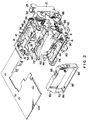
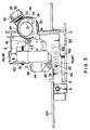
- Figs. 1 through 4 show the printer according to the preferred embodiment.
- the printer is a slip printer comprising an L-shaped chassis 2, a fixed frame 4 constituting side frames mounted on the chassis 2, a swing frame 8 supported by a supporting shaft 6 so as to be turned thereabout.
- the swing frame 8 constitutes a lever mechanism having the supporting shaft 6 as its fulcrum.
- a control circuit board 10 and a print mechanism 12 are respectively fixed to the fixed frame 4. That is, a carriage transfer motor 14 is fixed to the fixed frame 4, and torque of the carriage transfer motor 14 is transmitted to a carriage driving shaft 16 by way of a gear train.
- a gear 18 is attached to the carriage driving shaft 16, and a gear 20 attached to the chassis 2 meshes the gear 18.
- Cams 22 and 24 serving as a cam mechanism are attached to the gear 20.
- a movable arm 30 is provided so as to be operable by a trigger magnet 28 to move to or away from a protrusion 26 of the cam 22, and a tensile strength is applied to the movable arm 30 by a spring 32. When the trigger magnet 28 is not energized, a tip portion of the movable arm 30 is retained by the protrusion 26 so that the cam 22 is prevented from rotating by the spring 32.
- the cam 24 has a short diameter portion and a long diameter portion about a supporting shaft 34 as its rotary center.
- An operation portion 36 of the swing frame 8 contacts a working surface of the cam 24. That is, when the trigger magnet 28 is energized, the retention between the movable arm 30 and the cam 22 is released so that the rotation of the gear 20 is transmitted to the cam 24. At this time, the operation portion 36 is pressed downward when it contacts the long diameter portion of the cam 24 owing to the rotation of the cam 24.
- the print mechanism 12 has a print head 38 which is controlled by the carriage transfer motor 14 in its horizontal movement.
- a carriage 40 having the print head 38 thereon is slidably supported by a supporting shaft 42 which is fixed to the fixed frame 4.
- a head cover 44 serving as a cover for enveloping the print mechanism 12 is attached to the fixed frame 4.
- the head cover 44 is U-shaped so as to protrude in front of the fixed frame 4, and guide pieces 46, 48, 50, 52, 54, and 56 respectively protruding from the fixed frame 4 are disposed at the periphery of the head cover 44.
- a retaining hole 68 is defined in the guide piece 48 for retaining a retaining projection 66 of an ink ribbon cassette 60 therein, and fixing the same thereto.
- a retaining hole 72 is defined in the guide piece 50 for retaining a retaining projection 70 provided at the lower side of the ink ribbon cassette 60 therein and fixing the same thereto.
- a width between both side portions of the head cover 44 at the lower portion thereof is formed narrow, and a space portion 62 is defined between the outer periphery of the lower portion of the head cover 44 and the ink ribbon cassette 60.
- a driven roller 92 as a first roller corresponding to the driving rollers 78 and 80 is supported by a supporting shaft 94 between bearings 88 and 90 at the side portions of the head cover 44 fixed to the fixed frame 4.
- a platen 74, the driving rollers 78 and 80 as a second roller in a sheet feed mechanism 76 and a driving mechanism thereof are respectively disposed on the side of the swing frame 8, wherein the driving rollers 78 and 80 are supported by a driving shaft 82.
- the driving mechanism comprises a gear train 84 and a driving motor 86. Torque of the driving motor 86 is applied to the driving shaft 82 by way of the gear train 84.
- the driving motor 86 is attached to the swing frame 8 in the manner of protruding outside the swing frame 8.
- an interval between the bearings 88 and 90 formed on the head cover 44 corresponds to a width between the driving rollers 78 and 80, i.e., a width of a slip to be transferred, and it is formed to be narrower than the interval between arm portions 96 and 98 of the ink ribbon cassette 60. Accordingly, there is defined a space portion, i. e., a gap between inner sides of the arm portions 96 and 98 and outer surfaces of the bearings 88 and 90.
- a pushing-up mechanism 100 is disposed on the chassis 2 for pushing up the swing frame 8 toward the fixed frame 4. That is, a spring 102 is inserted between the chassis 2 and the swing frame 8 in a compressed state, so that the swing frame 8 is pushed upward by the spring 102. As a result, the driving rollers 78 and 80 are pressed against the working surface of the driven roller 92 by way of the slip to be transferred.
- a document table 104 serving as a guide plate is disposed on the chassis 2 so as to be interposed between the fixed frame 4 and the swing frame 8.
- the document table 104 is a guide means for inserting the slip to be printed between the driving rollers 78 and 80 and the working surface of the driven roller 92.
- FIG. 5 shows an arrangement of a control unit of the printer as shown in Figs. 1 through 4.
- a control portion 110 comprises a microcomputer composed of a CPU, a ROM and a RAM, an input/output unit, etc. and it is connected to a host computer, not shown.
- a control output issued by the control portion 110 is supplied to a timing pulse generator 112, the carriage transfer motor 14 and the trigger magnet 28.
- the timing pulse generator 112 generates timing pulses for rotating the carriage transfer motor 14.
- the carriage transfer motor 14 is a driving means of the carriage on which the print head is mounted, and its rotation is controlled by the control portion 110.
- the trigger magnet 28 is a means for applying torque to the cam 24 for turning the swing frame 8.
- a home position detector 114 is provided as a means for detecting a home position of the carriage 40, namely, detecting whether the carriage 40 is positioned at the left end position or not, and a detected output is applied to the control portion 110.
- the sheet feed mechanism 76 is integrally constituted on the swing frame 8 except the driven roller 92 supported on the fixed frame 4 independently of the mechanism on the fixed frame 4, it can be manufactured, and assembled independently and also manufactured separately.
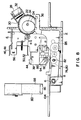
- the swing frame 8 is inclined about the supporting shaft 6 for preparing insertion of an ink ribbon 116 so as to increase the interval between the driving rollers 78, 80 and the driven roller 92.
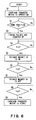
- Fig. 6 shows a flowchart of an expanding operation of the swing frame 8
- Fig. 7 shows an operation timing thereof.
- step S1 the carriage transfer motor 14 is operated.
- Fig. 7A shows an operating period of the carriage transfer motor 14.
- the control portion 110 detects whether the carriage 40 is transferred to the home position or not.
- Fig. 7B shows a detected output of the home position detector 114, wherein an L level period represents that the carriage 40 arrives at the home position.
- the program goes to a step S3 where timing pulses are counted as shown in Fig. 7C.
- T1, Tn1, Tn2 ... Tn3 represent counted values of the timing pulses.
- step S4 when the timing pulses reach the given counted value Tn1, the program goes to a step S5 where the trigger magnet 28 starts its energization.
- step S6 when the timing pulses reach the counted value Tn2 counting from the start of energization of the trigger magnet 28, the program goes to a step S7 where the energization of the trigger magnet 28 is released.
- Fig. 7D an H level period represents the energization period of the trigger magnet 28 wherein the other end of the movable arm 30 is attracted to the trigger magnet 28 against the spring 32 and it is released in its retention with the cam 22.
- step S8 the control portion 110 judges whether the timing pulses reach the counted value Tn3 or not.
- the program goes to a step S9 where the carriage transfer motor 14 is stopped.
- the carriage transfer motor 14 starts its rotation upon reception of an installation/removal instruction of the ink ribbon cassette 60, and the number of the timing pulses is counted.
- the rotation of the carriage transfer motor 14 is stopped.
- the trigger magnet 28 is energized during the period from the counted value Tn1 to Tn2, and at this time torque of the carriage transfer motor 14 is transmitted to the cam 24.
- the counted value Tn3 is so set as to allow the print head 38 to move from the home position to a predetermined position, for example, the center within the width of the lower portion of the head cover 44.
- the counted value Tn1 is so set as to allow the long diameter portion of the cam 24 to reach the operation portion 36 of the swing frame 8 when the timing pulses reach the counted value Tn3 or the carriage transfer motor 14 is stopped.
- the counted value Tn2 is set equal to a counted value from when the timing pulses reach the counted value Tn1 or the trigger magnet is energized to when the movable arm 30 is released in its engagement with the cam 22.
- the ink ribbon cassette 60 is inserted into the peripheral portion of the head cover 44 so as to position the head cover 44 between the arm portions 96 and 98 of the ink ribbon cassette 60.
- the ink ribbon 116 of the ink ribbon cassette 60 is passed through the interval between the driving rollers 78 and 80 and the driven roller 92, and is then inserted between the print head 38 of the printing mechanism 12 and the platen 74.
- Fig. 9 shows a state where the ink ribbon cassette 60 is installed in the printing mechanism.
- the print head 38 is enveloped by the head cover 44 after the head cover 44 is disposed on the fixed frame, so that the concave and convex portions provided in the tip portion of the print head are all covered with the head cover 44, and hence the ink ribbon is not caught by such concave and convex portions. Since the space portion 62 is defined between side walls of the bearings 88 and 90 of the head cover 44 and the inner sides of the arm portions 96 and 98 of the ink ribbon cassette 60, the ink ribbon cassette 60 can be easily and quickly installed in the printing mechanism while the ink ribbon 116 is not caught by any portions of the printing mechanism.
- the print head 38 When the ink ribbon cassette 60 is installed or removed, the print head 38 is moved to a position except both ends of the supporting shaft 42, for example, to the center in the preferred embodiment, in response to the installation/removal mode.
- the swing frame 8 When the print head 38 is moved to the center, the swing frame 8 is turned so as to set an interval between the driving rollers 78 and 80 and the driven roller 92 for allowing the ink ribbon 116 to pass therethrough. Further, when such an interval is set, the swing frame 8 moves downward, which does not cause any inconvenience for inserting the ink ribbon 116 and for installing the ink ribbon cassette 60, but facilitates the installation and removal of the ink ribbon cassette 60.
- the bearings 88 and 90 of the driven roller 92 attached to the head cover 44 correspond to the driving rollers 78 and 80 and also corresponding to the width of the slip to be printed. Accordingly, there is defined a gap between outer surfaces of the bearings 88 and 90 of the driven roller 92 and the inner sides of the arm portions 96 and 98 of the installed ink ribbon cassette 60. It is possible to visibly confirm condition of the ink ribbon 116 of the installed ink ribbon cassette 60 through this gap so as to prevent the start of printing in the inferior installation condition of the ink ribbon cassette 60.
- the head cover 44 envelopes the print head 38 which generates heat when printing, it is heated by the heat generated by the print head 38.
- the head cover 44 is formed of a metallic plate together with fixed frame 4, a radiating area of the print head 38 for radiating heat is increased so that the print head 38 is cooled, which contributes to prevention of overheating of the print head 38.
Landscapes
- Impression-Transfer Materials And Handling Thereof (AREA)
Priority Applications (1)
| Application Number | Priority Date | Filing Date | Title |
|---|---|---|---|
| EP98114510A EP0876924B1 (de) | 1995-01-13 | 1996-01-11 | Printer |
Applications Claiming Priority (4)
| Application Number | Priority Date | Filing Date | Title |
|---|---|---|---|
| JP7020990A JPH08187917A (ja) | 1995-01-13 | 1995-01-13 | プリンタ |
| JP20990/95 | 1995-01-13 | ||
| JP20992/95 | 1995-01-13 | ||
| JP7020992A JPH08187923A (ja) | 1995-01-13 | 1995-01-13 | プリンタ |
Related Child Applications (1)
| Application Number | Title | Priority Date | Filing Date |
|---|---|---|---|
| EP98114510A Division EP0876924B1 (de) | 1995-01-13 | 1996-01-11 | Printer |
Publications (1)
| Publication Number | Publication Date |
|---|---|
| EP0721847A1 true EP0721847A1 (de) | 1996-07-17 |
Family
ID=26357998
Family Applications (2)
| Application Number | Title | Priority Date | Filing Date |
|---|---|---|---|
| EP96300205A Withdrawn EP0721847A1 (de) | 1995-01-13 | 1996-01-11 | Drucker mit schwenkbarem Blattzuführungsteil |
| EP98114510A Expired - Lifetime EP0876924B1 (de) | 1995-01-13 | 1996-01-11 | Printer |
Family Applications After (1)
| Application Number | Title | Priority Date | Filing Date |
|---|---|---|---|
| EP98114510A Expired - Lifetime EP0876924B1 (de) | 1995-01-13 | 1996-01-11 | Printer |
Country Status (5)
| Country | Link |
|---|---|
| US (1) | US5868508A (de) |
| EP (2) | EP0721847A1 (de) |
| KR (1) | KR960029111A (de) |
| CN (1) | CN1121324C (de) |
| DE (1) | DE69617465T2 (de) |
Cited By (3)
| Publication number | Priority date | Publication date | Assignee | Title |
|---|---|---|---|---|
| EP0751001A3 (de) * | 1995-06-30 | 1998-06-24 | Canon Kabushiki Kaisha | Fördervorrichtung für ein Aufzeichnungsmedium |
| EP0822091A3 (de) * | 1996-08-01 | 1998-12-30 | Canon Kabushiki Kaisha | Aufzeichnungsgerät |
| CN1091691C (zh) * | 1996-09-18 | 2002-10-02 | 松下电器产业株式会社 | 图像印制装置 |
Families Citing this family (8)
| Publication number | Priority date | Publication date | Assignee | Title |
|---|---|---|---|---|
| JP3864941B2 (ja) * | 2003-08-22 | 2007-01-10 | 船井電機株式会社 | プリンタ |
| JP4394923B2 (ja) * | 2003-10-29 | 2010-01-06 | 富士通コンポーネント株式会社 | プリンタ |
| JP4421916B2 (ja) * | 2004-02-26 | 2010-02-24 | セイコーインスツル株式会社 | プリンタ装置 |
| US7586509B2 (en) | 2007-03-01 | 2009-09-08 | Kabushiki Kaisha Sato | Thermal transfer printer ribbon cassette apparatus and ribbon cassette mounting method |
| CN101407138B (zh) * | 2007-10-10 | 2010-06-23 | 诚研科技股份有限公司 | 物件移动装置 |
| JP2011178144A (ja) * | 2010-03-04 | 2011-09-15 | Seiko Epson Corp | 媒体処理装置のギャップ制御方法および媒体処理装置 |
| CN105365411B (zh) * | 2015-11-25 | 2018-05-29 | 亿和精密工业(苏州)有限公司 | 打印纸输送系统及具有该输送系统的打印机 |
| JP6668829B2 (ja) * | 2016-03-04 | 2020-03-18 | コニカミノルタ株式会社 | 画像形成装置 |
Citations (8)
| Publication number | Priority date | Publication date | Assignee | Title |
|---|---|---|---|---|
| WO1982001513A1 (en) * | 1980-11-04 | 1982-05-13 | Wang Laboratories | Print wheel mounting arrangement for print head and ribbon cartridge assembly |
| JPS62150148U (de) | 1986-03-14 | 1987-09-22 | ||
| US4784504A (en) * | 1986-08-29 | 1988-11-15 | Ncr Corporation | Multi-function printer |
| US4848941A (en) * | 1987-06-05 | 1989-07-18 | Minolta Camera Kabushiki Kaisha | Thermal printer |
| JPH028781Y2 (de) | 1983-05-24 | 1990-03-02 | ||
| US5006865A (en) * | 1988-04-20 | 1991-04-09 | Fuji Photo Film Co. | Method of recording gradation image in thermal printer |
| US5017033A (en) * | 1989-12-11 | 1991-05-21 | Ncr Corporation | Method of producing a printer which facilitates clearing a jammed document |
| EP0676295A2 (de) * | 1994-04-04 | 1995-10-11 | Seiko Epson Corporation | Druckvorrichtung und Steuerungsverfahren dafür |
Family Cites Families (6)
| Publication number | Priority date | Publication date | Assignee | Title |
|---|---|---|---|---|
| JPS63306067A (ja) * | 1987-06-08 | 1988-12-14 | スター精密株式会社 | 熱転写プリンタ− |
| JPH02269077A (ja) * | 1989-04-11 | 1990-11-02 | Brother Ind Ltd | プリンタの用紙給送装置 |
| JPH04126276A (ja) * | 1989-07-21 | 1992-04-27 | Canon Inc | インクシートカートリツジ及び前記インクシートカートリツジを装填可能な記録装置 |
| DE4008541C1 (de) * | 1990-03-16 | 1991-11-21 | Siemens Nixdorf Informationssysteme Ag, 4790 Paderborn, De | |
| IT1239396B (it) * | 1990-03-20 | 1993-10-20 | Printax | Apparecchiatura stampante portatile |
| JPH05112022A (ja) * | 1991-10-24 | 1993-05-07 | Sony Corp | プリンタ |
-
1996
- 1996-01-09 KR KR1019960000266A patent/KR960029111A/ko not_active Abandoned
- 1996-01-11 US US08/584,064 patent/US5868508A/en not_active Expired - Fee Related
- 1996-01-11 DE DE69617465T patent/DE69617465T2/de not_active Expired - Fee Related
- 1996-01-11 EP EP96300205A patent/EP0721847A1/de not_active Withdrawn
- 1996-01-11 EP EP98114510A patent/EP0876924B1/de not_active Expired - Lifetime
- 1996-01-13 CN CN96104328A patent/CN1121324C/zh not_active Expired - Fee Related
Patent Citations (8)
| Publication number | Priority date | Publication date | Assignee | Title |
|---|---|---|---|---|
| WO1982001513A1 (en) * | 1980-11-04 | 1982-05-13 | Wang Laboratories | Print wheel mounting arrangement for print head and ribbon cartridge assembly |
| JPH028781Y2 (de) | 1983-05-24 | 1990-03-02 | ||
| JPS62150148U (de) | 1986-03-14 | 1987-09-22 | ||
| US4784504A (en) * | 1986-08-29 | 1988-11-15 | Ncr Corporation | Multi-function printer |
| US4848941A (en) * | 1987-06-05 | 1989-07-18 | Minolta Camera Kabushiki Kaisha | Thermal printer |
| US5006865A (en) * | 1988-04-20 | 1991-04-09 | Fuji Photo Film Co. | Method of recording gradation image in thermal printer |
| US5017033A (en) * | 1989-12-11 | 1991-05-21 | Ncr Corporation | Method of producing a printer which facilitates clearing a jammed document |
| EP0676295A2 (de) * | 1994-04-04 | 1995-10-11 | Seiko Epson Corporation | Druckvorrichtung und Steuerungsverfahren dafür |
Cited By (4)
| Publication number | Priority date | Publication date | Assignee | Title |
|---|---|---|---|---|
| EP0751001A3 (de) * | 1995-06-30 | 1998-06-24 | Canon Kabushiki Kaisha | Fördervorrichtung für ein Aufzeichnungsmedium |
| EP0822091A3 (de) * | 1996-08-01 | 1998-12-30 | Canon Kabushiki Kaisha | Aufzeichnungsgerät |
| US5947615A (en) * | 1996-08-01 | 1999-09-07 | Canon Kabushiki Kaisha | Recording apparatus |
| CN1091691C (zh) * | 1996-09-18 | 2002-10-02 | 松下电器产业株式会社 | 图像印制装置 |
Also Published As
| Publication number | Publication date |
|---|---|
| US5868508A (en) | 1999-02-09 |
| KR960029111A (ko) | 1996-08-17 |
| DE69617465D1 (de) | 2002-01-10 |
| CN1121324C (zh) | 2003-09-17 |
| DE69617465T2 (de) | 2002-06-06 |
| EP0876924A1 (de) | 1998-11-11 |
| CN1134888A (zh) | 1996-11-06 |
| EP0876924B1 (de) | 2001-11-28 |
Similar Documents
| Publication | Publication Date | Title |
|---|---|---|
| JPH0425344Y2 (de) | ||
| US6232996B1 (en) | Thermal printer | |
| EP0876924B1 (de) | Printer | |
| EP0222600B1 (de) | Papierzuführung für einen Drucker | |
| US4946297A (en) | Printing apparatus | |
| EP0718109A2 (de) | Papierabgabevorrichtung | |
| US5308175A (en) | Printer with reverse sheet feed path to sheet inlet | |
| JPH0671807B2 (ja) | 印字装置 | |
| EP0313404B1 (de) | Anordnung zur selbsttätigen Papierzufuhr in einem Drucker, versehen mit einem Bügelbetätigungsmechanismus | |
| EP0223523B1 (de) | Verfahren und Vorrichtung zum Betrieb eines Druckers | |
| JPH0462552B2 (de) | ||
| JP3656671B2 (ja) | 小型プリンタ | |
| EP0516061A1 (de) | Bilderzeugungsgerät | |
| JPH04125250A (ja) | プリンタ | |
| JPH08187923A (ja) | プリンタ | |
| JP2623560B2 (ja) | プリンタ用紙送り機構 | |
| KR100201846B1 (ko) | 비디오 프린터 | |
| JP2771646B2 (ja) | 用紙押えローラ開閉用モータのステップ数決定方式 | |
| JPS62191339A (ja) | 記録装置の給送機構 | |
| KR200156005Y1 (ko) | 프린터의 급지장치 | |
| JP2001080148A (ja) | インクリボン用カセット | |
| JP2771647B2 (ja) | 用紙押えローラ開閉用モータのステップ数補正方式 | |
| JP2949810B2 (ja) | プリンタの自動給紙装置 | |
| KR960001970B1 (ko) | 프린터의 용지 자동 이송장치 | |
| JP2898656B2 (ja) | プリンタの制御方法 |
Legal Events
| Date | Code | Title | Description |
|---|---|---|---|
| PUAI | Public reference made under article 153(3) epc to a published international application that has entered the european phase |
Free format text: ORIGINAL CODE: 0009012 |
|
| AK | Designated contracting states |
Kind code of ref document: A1 Designated state(s): DE GB |
|
| 17P | Request for examination filed |
Effective date: 19961223 |
|
| 17Q | First examination report despatched |
Effective date: 19980115 |
|
| STAA | Information on the status of an ep patent application or granted ep patent |
Free format text: STATUS: THE APPLICATION IS DEEMED TO BE WITHDRAWN |
|
| 18D | Application deemed to be withdrawn |
Effective date: 19981231 |