EP0721904B1 - Enrouleur - Google Patents
Enrouleur Download PDFInfo
- Publication number
- EP0721904B1 EP0721904B1 EP95304158A EP95304158A EP0721904B1 EP 0721904 B1 EP0721904 B1 EP 0721904B1 EP 95304158 A EP95304158 A EP 95304158A EP 95304158 A EP95304158 A EP 95304158A EP 0721904 B1 EP0721904 B1 EP 0721904B1
- Authority
- EP
- European Patent Office
- Prior art keywords
- rolls
- carriage
- group
- roll
- tracking
- Prior art date
- Legal status (The legal status is an assumption and is not a legal conclusion. Google has not performed a legal analysis and makes no representation as to the accuracy of the status listed.)
- Expired - Lifetime
Links
Images


Classifications
-
- B—PERFORMING OPERATIONS; TRANSPORTING
- B65—CONVEYING; PACKING; STORING; HANDLING THIN OR FILAMENTARY MATERIAL
- B65H—HANDLING THIN OR FILAMENTARY MATERIAL, e.g. SHEETS, WEBS, CABLES
- B65H18/00—Winding webs
- B65H18/08—Web-winding mechanisms
-
- B—PERFORMING OPERATIONS; TRANSPORTING
- B65—CONVEYING; PACKING; STORING; HANDLING THIN OR FILAMENTARY MATERIAL
- B65H—HANDLING THIN OR FILAMENTARY MATERIAL, e.g. SHEETS, WEBS, CABLES
- B65H18/00—Winding webs
- B65H18/02—Supporting web roll
-
- B—PERFORMING OPERATIONS; TRANSPORTING
- B65—CONVEYING; PACKING; STORING; HANDLING THIN OR FILAMENTARY MATERIAL
- B65H—HANDLING THIN OR FILAMENTARY MATERIAL, e.g. SHEETS, WEBS, CABLES
- B65H18/00—Winding webs
- B65H18/08—Web-winding mechanisms
- B65H18/26—Mechanisms for controlling contact pressure on winding-web package, e.g. for regulating the quantity of air between web layers
-
- B—PERFORMING OPERATIONS; TRANSPORTING
- B65—CONVEYING; PACKING; STORING; HANDLING THIN OR FILAMENTARY MATERIAL
- B65H—HANDLING THIN OR FILAMENTARY MATERIAL, e.g. SHEETS, WEBS, CABLES
- B65H2301/00—Handling processes for sheets or webs
- B65H2301/40—Type of handling process
- B65H2301/41—Winding, unwinding
- B65H2301/414—Winding
- B65H2301/4148—Winding slitting
-
- B—PERFORMING OPERATIONS; TRANSPORTING
- B65—CONVEYING; PACKING; STORING; HANDLING THIN OR FILAMENTARY MATERIAL
- B65H—HANDLING THIN OR FILAMENTARY MATERIAL, e.g. SHEETS, WEBS, CABLES
- B65H2511/00—Dimensions; Position; Numbers; Identification; Occurrences
- B65H2511/10—Size; Dimensions
- B65H2511/14—Diameter, e.g. of roll or package
-
- B—PERFORMING OPERATIONS; TRANSPORTING
- B65—CONVEYING; PACKING; STORING; HANDLING THIN OR FILAMENTARY MATERIAL
- B65H—HANDLING THIN OR FILAMENTARY MATERIAL, e.g. SHEETS, WEBS, CABLES
- B65H2513/00—Dynamic entities; Timing aspects
- B65H2513/10—Speed
Definitions
- Fig. 3 is a side view of a second embodiment of the invention.
- Fig. 4 is a side view of a third embodiment of the invention.
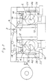
- an apparatus which includes a plurality of slitting blades 2 for slitting a web material 4 such as paper, plastic film and the like into a plurality of webs or web materials.
- the apparatus is intended to then wind the web materials 4 to form a plurality of rolls.
- the rolls are divided into two groups, one group of rolls 6 being arranged side by side and coaxially to each other at the front of the apparatus, the other group of rolls 6' being arranged side by side and coaxially to each other at the rear of the apparatus.
- the web materials 4 are alternately directed to one group of rolls 6 and the other group of rolls 6'.
- the rolls 6 and 6' each includes a core 8 disposed between a pair of side plates 10.
- the side plates 10 include chucking means not shown for chucking the opposite ends of the cores 8.
- the chucking means are rotated integrally with the cores 8 by motor means not shown to wind the web materials 4 about the cores 8 to thereby form the rolls 6 and 6'.
- Tracking rollers 12 are disposed on the upper side of one group of rolls 6 and the upper side of the other group of rolls 6' and mounted on levers 14 for rotation respectively.
- the levers 14 are mounted on a frame 16 for swinging movement.
- the tracking rollers 12 are opposed to the corresponding groups of rolls 6 and 6' vertically.
- the web materials 4 are directed to the rolls 6 and 6' via the tracking rollers 12.
- the apparatus includes actuator means comprising a plurality of air or hydraulic cylinders 18 which are mounted on the frame 16 and operatively connected to the levers 14.
- the cylinders 18 cooperate with the levers 14 to press the tracking rollers 12 against the corresponding groups of rolls 6 and 6' with a contact pressure therebetween to conveniently wind the web materials 4 onto the rolls 6 and 6'.
- the apparatus further includes carriage means comprising a common carriage 20 for one group of rolls 6 and the other group of rolls 6'.
- the side plates 10 are attached to the carriage 20 so that one group of rolls 6 and the other group of rolls 6' are supported by the carriage 20, as shown in Fig. 2.
- the carriage 20 is mounted on a pillar 22 for vertical movement.
- the apparatus further includes drive means comprising a motor 24 for rotating ball screws 26 extending vertically and along the pillar 22.
- the carriage 20 includes nut members 28 fixedly attached thereto and engaged with the ball screws 26.
- the motor 24 is connected to a drive shaft 30 extending horizontally and supported by brackets 32 for rotation.
- the drive shaft 30 includes worms 34 attached thereto and received in the brackets 32.
- the ball screws 26 each includes a worm wheel 36 attached thereto, received in the bracket 32 and engaged with the worm 34.
- the ball screws 26 are rotated by the worms 34 and the worm wheels 36 when the drive shaft 30 is rotated by the motor 24 so that the carriage 20, the side plates 10 and the rolls 6 and 6' are moved vertically and along the pillar 22 by the ball screws 26 and the nut members 28.
- a control unit not shown is provided to compute the increasing diameters of the rolls 6 and 6', and drive the motor 24 and control the speed thereof in response to the increases in diameters of the rolls 6 and 6'.
- the apparatus includes roll lifters 38, cross cutters 40, web holders 42 and core feeders 44, which are known and therefore not explained in details herein.
- the rolls 6 and 6' increase in diameters more and more as the web materials 4 are wound.
- the control unit drives the motor 24 and controls the speed thereof so that the ball screws 26 and the nut members 28 move the carriage 20, the side plates 10 and the rolls 6 and 6' downwardly in response to the increases in diameters of the rolls 6 and 6'. This enables the rolls 6 and 6' to increase in diameters.
- the tracking rollers 12 are therefore held in position.
- the control unit drives the motor 24 to move the carriage 20 downwardly a distance so that the rolls 6 and 6' are retracted and spaced from the tracking rollers 12.
- the cross cutters 40 are then moved toward the web materials 4 between the tracking rollers 12 and the rolls 6 and 6' to cut the web materials 4 widthwise.
- the leading ends of the web materials 4 are absorbed or adhered to the web holders 42.
- the lifters 38 are moved upwardly toward the rolls 6 and 6'.
- the rolls 6 and 6' are then released from the chucking means of the side plates 10 and supported on the lifters 38.
- the lifters 38 are then moved downwardly to take out the rolls 6 and 6'.
- the cross cutters 40 are moved back to the position shown in Fig. 1.
- the carriage 20 are then moved upwardly to the position shown in Fig. 1.
- the cylinders 18 cooperate with the levers 14 to lift the tracking rollers 12 from the side plates 10. New cores are then led by the core feeders 44 and chucked by the chucking means of the side plates 10.
- the cylinders 18 then lower and press the tracking rollers 12 against the web materials 4 on the cores.
- the chucking means is again rotated integrally with the cores to wind the web materials 4.
- the carriage means comprises two separate carriages 46 and 46'.
- the side plates 10 are attached to the carriages 46 and 46' so that one group of rolls 6 are supported by one carriage 46 and the other group of rolls 6' are supported by the other carriage 46'.
- the carriages 46 and 46' are mounted on pillars 22 for vertical movement.
- the carriages 46 and 46' each includes nut members 28 fixedly attached thereto and engaged with ball screws 26 which extend along the pillars 22 and rotated by a motor 24, as the apparatus in Fig. 1.
- the apparatus includes carriage means comprising a common carriage 48 for the tracking rollers 12 and the cylinders 18.
- the tracking rollers 12 are mounted on levers 14 for rotation respectively, the levers 14 being mounted on the carriage 48 for swinging movement.
- the cylinders 18 are mounted on the carriage 48 and operatively connected to the levers 14 so that the tracking rollers 12 and the cylinders 18 are supported by the carriage 48.
- the carriage 48 is mounted on the pillar 22 for vertical movement.
- the carriage 48 includes nut members 50 fixedly attached thereto and engaged with the hall screws 26 which extend along the pillar 22 and rotated by a motor 24, as the apparatus in Fig. 1.
- the carriage means may comprise two separate carriages, the tracking rollers 12 and the cylinders 18 for one group of rolls 6 being supported by one carriage, the tracking rollers 12 and the cylinders 18 for the other group of rolls 6' being supported by the other carriage.
- the operator extends his hands from the outside of the apparatus to manually direct the web materials 4 to the tracking rollers 12 and the cores 8.
- the tracking rollers 12 are positioned not on the inner side of the cores 8 but upper side thereof. It is therefore easy to manually direct the web materials 4 to the tracking rollers 12 and the cores 8 without obstruction. It does not take much labour and time.
- a large space is not required in a horizontal direction since the tracking rollers 12 are opposed to the corresponding groups of rolls 6 and 6' not horizontally but vertically, the carriage means 20, 46, 46' or 48 being moved not horizontally but vertically.
- only the carriage means 20, 46, 46' or 48 have to move downwardly or upwardly.
- a single means such as a motor 24 can be used therefor. Two separate drive means are not required. Costs are therefore reduced.
Landscapes
- Replacement Of Web Rolls (AREA)
- Winding Of Webs (AREA)
Claims (7)
- Appareil pour enrouler un matériau en bande tel que du papier, un film plastique et similaire, pour former au moins un rouleau (6, 6'), ledit appareil comportant au moins un galet de roulement (12), un actionneur (18) pour presser ledit galet de roulement (12) contre ledit rouleau (6, 6'), un moyen de chariot (20, 46, 46') qui supporte ledit rouleau (6, 6'), et un moyen d'entraínement (24) pour déplacer ledit moyen de chariot (20, 46, 46'), ledit appareil étant caractérisé en ce que ledit galet de roulement (12) est disposé du côté supérieur dudit rouleau (6, 6'), et en ce que ledit moyen d'entraínement (24) est prévu pour déplacer ledit moyen de chariot (20, 46, 46') vers le bas en réponse à l'augmentation de diamètre dudit rouleau (6, 6') pour ainsi permettre audit rouleau (6, 6') d'augmenter de diamètre.
- Appareil selon la revendication 1, dans lequel ledit appareil est adapté pour fendre un matériau en bande tel que du papier, un film plastique et similaire en une pluralité de bandes puis enrouler les bandes pour former une pluralité desdits rouleaux (6, 6'), lesdits rouleaux (6, 6') étant en deux groupes, un groupe de rouleaux (6) étant arrangé de manière juxtaposée et coaxialement les uns aux autres à l'avant de l'appareil, l'autre groupe de rouleaux (6') étant arrangé de manière juxtaposée et coaxialement les uns aux autres à l'arrière de l'appareil, ledit appareil comportant une pluralité desdits galets de roulement (12) disposés sur le côté supérieur dudit premier groupe de rouleaux (6) et sur le côté supérieur de l'autre groupe de rouleaux (6'), et une pluralité desdits actionneurs (18) pour presser lesdits galets de roulement (12) contre les groupes correspondants de rouleaux (6, 6'), et ledit premier groupe de rouleaux (6) et l'autre groupe de rouleaux (6') étant tous deux supportés par ledit moyen de chariot (20, 46, 46'), ledit moyen d'entraínement déplaçant ledit moyen de chariot (20, 46, 46') vers le bas en réponse aux augmentations de diamètre desdits rouleaux (6, 6') pour ainsi permettre auxdits rouleaux (6, 6') d'augmenter de diamètre.
- Appareil selon la revendication 2, dans lequel ledit moyen de chariot comprend un chariot commun (20) pour ledit premier groupe de rouleaux (6) et l'autre groupe de rouleaux (6'), lesdits rouleaux (6, 6') comportant chacun un coeur (8) disposé entre une paire de plateaux latéraux (10) qui sont attachés audit chariot (20), lesdits plateaux latéraux (10) comportant des moyens de mandrin pour serrer les extrémités opposées desdits coeurs (8), lesdits moyens de mandrin étant entraínés en rotation en même temps que lesdits coeurs (8) pour enrouler lesdites bandes autour desdits coeurs (8) pour ainsi former les rouleaux (6, 6'), ledit chariot (20) étant monté sur un pilier (22) permettant un mouvement vertical, ledit moyen d'entraínement comprenant un moteur (24) pour entraíner en rotation un moyen de vis à billes (26) s'étendant le long dudit pilier (22), et ledit chariot (20) comportant un moyen d'écrou (28) attaché fixement à celui-ci et engagé avec ledit moyen de vis à billes (26) pour déplacer ledit chariot (20) le long dudit pilier (22).
- Appareil selon la revendication 2, dans lequel ledit moyen de chariot comprend deux chariots séparés (46, 46'), un groupe de rouleaux (6) étant supporté par l'un des chariots (46), et l'autre groupe de rouleaux (6') étant supporté par l'autre chariot (46'), lesdits rouleaux (6, 6') comportant chacun un coeur (8) disposé entre une paire de plateaux latéraux (10) qui sont attachés auxdits chariots (46, 46'), lesdits plateaux latéraux (10) comportant des moyens de mandrin pour serrer les extrémités opposées desdits coeurs (8), lesdits moyens de mandrin étant entraínés en rotation en même temps que lesdits coeurs (8) pour enrouler lesdites bandes autour desdits coeurs (8) pour ainsi former les rouleaux (6, 6'), lesdits chariots (46, 46') étant montés sur des piliers (22) permettant un mouvement vertical, ledit moyen d'entraínement comprenant un moteur (24) pour entraíner en rotation un moyen de vis à billes (26) s'étendant le long desdits piliers (22), et lesdits chariots (46, 46') comportant chacun un moyen d'écrou (28) attaché fixement à ceux-ci et engagé avec ledit moyen de vis à billes (26) pour déplacer lesdits chariots (46, 46') le long desdits piliers (22).
- Appareil pour enrouler un matériau en bande tel que du papier, un film plastique et similaire, pour former au moins un rouleau (6, 6'), ledit appareil comportant au moins un galet de roulement (12), un actionneur (18) pour presser ledit galet de roulement (12) contre ledit rouleau (6, 6'), un moyen de chariot (48) qui supporte ledit galet de roulement (12) et ledit actionneur (18), et un moyen d'entraínement (24) pour déplacer ledit moyen de chariot (48), ledit appareil étant caractérisé en ce que ledit galet de roulement (12) est disposé du côté supérieur dudit rouleau (6, 6'), et en ce que ledit moyen d'entraínement (24) est prévu pour déplacer ledit moyen de chariot (48) vers le haut en réponse à l'augmentation de diamètre dudit rouleau (6, 6') pour ainsi permettre audit rouleau (6, 6') d'augmenter de diamètre.
- Appareil selon la revendication 5, dans lequel ledit appareil est adapté pour fendre un matériau en bande tel que du papier, un film plastique et similaire en une pluralité de bandes puis enrouler les bandes pour former une pluralité desdits rouleaux (6, 6'), lesdits rouleaux (6, 6') étant en deux groupes, un groupe de rouleaux (6) étant arrangé de manière juxtaposée et coaxialement les uns aux autres à l'avant de l'appareil, l'autre groupe de rouleaux (6') étant arrangé de manière juxtaposée et coaxialement les uns aux autres à l'arrière de l'appareil, ledit appareil comportant une pluralité desdits galets de roulement (12) disposés sur le côté supérieur dudit premier groupe de rouleaux (6) et sur le côté supérieur de l'autre groupe de rouleaux (6'), et une pluralité desdits actionneurs (18) pour presser lesdits galets de roulement (12) contre les groupes correspondants de rouleaux (6, 6'), et les galets de roulement (12) et les actionneurs (18) étant tous supportés par ledit moyen de chariot (48), ledit moyen d'entraínement déplaçant ledit moyen de chariot (48) vers le haut en réponse aux augmentations de diamètre desdits rouleaux (6, 6') pour ainsi permettre auxdits rouleaux (6, 6') d'augmenter de diamètre.
- Appareil selon la revendication 6, dans lequel ledit moyen de chariot comprend un chariot commun (48) pour lesdits galets de roulement (12) et lesdits actionneurs (18), lesdits galets de roulement (12) étant montés sur les leviers (14) permettant une rotation respective, lesdits leviers (14) étant montés sur ledit chariot (48) pour permettre un mouvement de pivotement, lesdits actionneurs comprenant une pluralité de vérins pneumatiques ou hydrauliques (18) qui sont montés sur ledit chariot (48) et sont connectés de manière opérationnelle auxdits leviers (14) pour presser lesdits galets de roulement (12) contre lesdits rouleaux (6, 6'), ledit chariot (48) étant monté sur un pilier (22) permettant un mouvement vertical, ledit moyen d'entraínement comprenant un moteur (24) pour entraíner en rotation un moyen de vis à billes (26) s'étendant le long dudit pilier (22), et ledit chariot (48) comportant un moyen d'écrou (50) attaché fixement à celui-ci et engagé avec ledit moyen de vis à billes (26) pour déplacer ledit chariot (48) le long dudit pilier (22).
Applications Claiming Priority (3)
| Application Number | Priority Date | Filing Date | Title |
|---|---|---|---|
| JP2135695 | 1995-01-12 | ||
| JP21356/95 | 1995-01-12 | ||
| JP2135695 | 1995-01-12 |
Publications (2)
| Publication Number | Publication Date |
|---|---|
| EP0721904A1 EP0721904A1 (fr) | 1996-07-17 |
| EP0721904B1 true EP0721904B1 (fr) | 2000-05-10 |
Family
ID=12052821
Family Applications (1)
| Application Number | Title | Priority Date | Filing Date |
|---|---|---|---|
| EP95304158A Expired - Lifetime EP0721904B1 (fr) | 1995-01-12 | 1995-06-14 | Enrouleur |
Country Status (4)
| Country | Link |
|---|---|
| US (1) | US5653400A (fr) |
| EP (1) | EP0721904B1 (fr) |
| KR (1) | KR100357938B1 (fr) |
| DE (1) | DE69516832T2 (fr) |
Cited By (1)
| Publication number | Priority date | Publication date | Assignee | Title |
|---|---|---|---|---|
| US7735771B2 (en) | 2004-06-30 | 2010-06-15 | The Procter & Gamble Company | Apparatus and method for the concurrent converting of multiple web materials |
Families Citing this family (7)
| Publication number | Priority date | Publication date | Assignee | Title |
|---|---|---|---|---|
| DE19738519B4 (de) * | 1997-09-03 | 2005-04-28 | Reifenhaeuser Masch | Vorrichtung zum Aufwickeln einer Bahn und Verfahren zum Betrieb der Vorrichtung |
| WO2002085767A1 (fr) * | 2001-04-20 | 2002-10-31 | Davis-Standard Corporation | Enrouleur de film central, a position fixe multiple, et procede pour enrouler du tissu |
| US8097109B2 (en) | 2004-12-14 | 2012-01-17 | The Proctor & Gamble Company | Method for the concurrent converting of multiple web materials |
| CN101970321B (zh) * | 2007-10-16 | 2014-04-09 | 格罗特斯工程公司 | 索引卷绕机上卷绕芯的设备 |
| KR101059509B1 (ko) | 2008-10-14 | 2011-08-25 | 에스티엑스조선해양 주식회사 | 호스의 자동 공급 및 회수장치 |
| CN106429563B (zh) * | 2016-09-26 | 2018-06-19 | 佛山市顺德区一骏实业有限公司 | 一种玻璃膜生产线的绕膜机构 |
| CN107161744A (zh) * | 2017-06-29 | 2017-09-15 | 苏州市丹纺纺织研发有限公司 | 一种纺织机械用布料收卷装置 |
Family Cites Families (6)
| Publication number | Priority date | Publication date | Assignee | Title |
|---|---|---|---|---|
| US1853384A (en) * | 1928-07-16 | 1932-04-12 | Graton & Knight Company | Belt winding machine |
| BR8201614A (pt) * | 1981-04-30 | 1983-02-08 | Jagenberg Werke Ag | Dispositivo para o enrolamento separado de secoes de material divididas longitudinalmente |
| DE3629024C3 (de) * | 1986-08-27 | 1994-09-01 | Jagenberg Ag | Vorrichtung zum Einbringen einer Wickelhülse in eine Wickelmaschine |
| DE3832601C1 (en) * | 1988-09-26 | 1989-12-07 | J.M. Voith Gmbh, 7920 Heidenheim, De | Winding machine for web-like material, especially paper |
| JP2958570B2 (ja) * | 1990-05-21 | 1999-10-06 | 株式会社西村製作所 | ウエブ巻取装置 |
| US5308008A (en) * | 1992-03-18 | 1994-05-03 | Rueegg Anton | Method and apparatus for producing rolls |
-
1995
- 1995-04-14 KR KR1019950008742A patent/KR100357938B1/ko not_active Expired - Fee Related
- 1995-06-06 US US08/466,674 patent/US5653400A/en not_active Expired - Lifetime
- 1995-06-14 EP EP95304158A patent/EP0721904B1/fr not_active Expired - Lifetime
- 1995-06-14 DE DE69516832T patent/DE69516832T2/de not_active Expired - Lifetime
Cited By (1)
| Publication number | Priority date | Publication date | Assignee | Title |
|---|---|---|---|---|
| US7735771B2 (en) | 2004-06-30 | 2010-06-15 | The Procter & Gamble Company | Apparatus and method for the concurrent converting of multiple web materials |
Also Published As
| Publication number | Publication date |
|---|---|
| DE69516832T2 (de) | 2000-10-12 |
| US5653400A (en) | 1997-08-05 |
| EP0721904A1 (fr) | 1996-07-17 |
| KR100357938B1 (ko) | 2003-03-26 |
| KR960029216A (ko) | 1996-08-17 |
| DE69516832D1 (de) | 2000-06-15 |
Similar Documents
| Publication | Publication Date | Title |
|---|---|---|
| EP0427408B1 (fr) | Dispositif pour enrouler en continu des feuilles continues | |
| US5624525A (en) | Sheet sticking apparatus | |
| EP0721904B1 (fr) | Enrouleur | |
| JPS58500199A (ja) | 巾の変更自在なウェブ裁断巻取装置 | |
| GB1600070A (en) | Web feeding or winding-up apparatus | |
| JP2793166B2 (ja) | 貯蔵ウエブロールから繰り出されるウエブの部分を処理するための装置 | |
| GB2288594A (en) | Winding webs | |
| EP0959009B1 (fr) | Dispositif et procédé pour enlever le matériau d'emballage d'un rouleau de matériau en bande | |
| US4415128A (en) | Rider rolls in support-roll winding machines | |
| US5354006A (en) | Paper web supply assembly | |
| JPH0624615A (ja) | フィルムアキュムレータを備えたスリッター、及びフィルム巻取速度制御装置 | |
| JP3989006B2 (ja) | 巻き箔材を加工する機械のための巻き箔材の支持及び駆動用モジュール | |
| EP0132390B1 (fr) | Dispositif d'enroulement monté sur une poutre orientable | |
| JPS6055416B2 (ja) | ウエブ巻取装置 | |
| JP4195187B2 (ja) | ロールを形成するためのシート状連続製品の巻き取り装置 | |
| CN217437293U (zh) | 四工位落地式收卷机 | |
| WO2019237218A1 (fr) | Machine d'asservissement de coupe et de rectification de bord tout-en-une | |
| JP3171780B2 (ja) | ウエブ巻取装置 | |
| JPS63262360A (ja) | センタ−駆動巻取型スリツタ− | |
| US4697752A (en) | Coil winding machine | |
| GB2311774A (en) | Combining webs into a single multi-ply wound web | |
| JPH07165356A (ja) | シート及びフィルム巻取機 | |
| SU1375546A1 (ru) | Устройство дл размотки лент | |
| JPH03115044A (ja) | 巻取紙自動仕立装置 | |
| JPS62130196A (ja) | ウエブ裁断装置 |
Legal Events
| Date | Code | Title | Description |
|---|---|---|---|
| PUAI | Public reference made under article 153(3) epc to a published international application that has entered the european phase |
Free format text: ORIGINAL CODE: 0009012 |
|
| AK | Designated contracting states |
Kind code of ref document: A1 Designated state(s): DE FR GB IT |
|
| 17P | Request for examination filed |
Effective date: 19961218 |
|
| 17Q | First examination report despatched |
Effective date: 19980506 |
|
| GRAG | Despatch of communication of intention to grant |
Free format text: ORIGINAL CODE: EPIDOS AGRA |
|
| GRAG | Despatch of communication of intention to grant |
Free format text: ORIGINAL CODE: EPIDOS AGRA |
|
| GRAH | Despatch of communication of intention to grant a patent |
Free format text: ORIGINAL CODE: EPIDOS IGRA |
|
| GRAH | Despatch of communication of intention to grant a patent |
Free format text: ORIGINAL CODE: EPIDOS IGRA |
|
| GRAA | (expected) grant |
Free format text: ORIGINAL CODE: 0009210 |
|
| AK | Designated contracting states |
Kind code of ref document: B1 Designated state(s): DE FR GB IT |
|
| REF | Corresponds to: |
Ref document number: 69516832 Country of ref document: DE Date of ref document: 20000615 |
|
| ITF | It: translation for a ep patent filed | ||
| ET | Fr: translation filed | ||
| K2C3 | Correction of patent specification (complete document) published |
Effective date: 20000510 |
|
| PLBE | No opposition filed within time limit |
Free format text: ORIGINAL CODE: 0009261 |
|
| STAA | Information on the status of an ep patent application or granted ep patent |
Free format text: STATUS: NO OPPOSITION FILED WITHIN TIME LIMIT |
|
| 26N | No opposition filed | ||
| REG | Reference to a national code |
Ref country code: GB Ref legal event code: IF02 |
|
| PGFP | Annual fee paid to national office [announced via postgrant information from national office to epo] |
Ref country code: FR Payment date: 20100706 Year of fee payment: 16 |
|
| PGFP | Annual fee paid to national office [announced via postgrant information from national office to epo] |
Ref country code: IT Payment date: 20100621 Year of fee payment: 16 |
|
| PGFP | Annual fee paid to national office [announced via postgrant information from national office to epo] |
Ref country code: GB Payment date: 20100618 Year of fee payment: 16 Ref country code: DE Payment date: 20100625 Year of fee payment: 16 |
|
| GBPC | Gb: european patent ceased through non-payment of renewal fee |
Effective date: 20110614 |
|
| PG25 | Lapsed in a contracting state [announced via postgrant information from national office to epo] |
Ref country code: IT Free format text: LAPSE BECAUSE OF NON-PAYMENT OF DUE FEES Effective date: 20110614 |
|
| REG | Reference to a national code |
Ref country code: FR Ref legal event code: ST Effective date: 20120229 |
|
| REG | Reference to a national code |
Ref country code: DE Ref legal event code: R119 Ref document number: 69516832 Country of ref document: DE Effective date: 20120103 |
|
| PG25 | Lapsed in a contracting state [announced via postgrant information from national office to epo] |
Ref country code: FR Free format text: LAPSE BECAUSE OF NON-PAYMENT OF DUE FEES Effective date: 20110630 Ref country code: DE Free format text: LAPSE BECAUSE OF NON-PAYMENT OF DUE FEES Effective date: 20120103 |
|
| PG25 | Lapsed in a contracting state [announced via postgrant information from national office to epo] |
Ref country code: GB Free format text: LAPSE BECAUSE OF NON-PAYMENT OF DUE FEES Effective date: 20110614 |