EP0721907A2 - Détecteur de bord par ultra-sons pour la détection du bord d'une bande de matière - Google Patents
Détecteur de bord par ultra-sons pour la détection du bord d'une bande de matière Download PDFInfo
- Publication number
- EP0721907A2 EP0721907A2 EP95119889A EP95119889A EP0721907A2 EP 0721907 A2 EP0721907 A2 EP 0721907A2 EP 95119889 A EP95119889 A EP 95119889A EP 95119889 A EP95119889 A EP 95119889A EP 0721907 A2 EP0721907 A2 EP 0721907A2
- Authority
- EP
- European Patent Office
- Prior art keywords
- sensor
- edge
- calibration
- counter
- sensors
- Prior art date
- Legal status (The legal status is an assumption and is not a legal conclusion. Google has not performed a legal analysis and makes no representation as to the accuracy of the status listed.)
- Granted
Links
- 239000000463 material Substances 0.000 title claims description 7
- 238000005259 measurement Methods 0.000 claims description 15
- 230000006870 function Effects 0.000 claims description 5
- 238000010586 diagram Methods 0.000 description 8
- 238000000034 method Methods 0.000 description 4
- 230000008569 process Effects 0.000 description 4
- 238000001514 detection method Methods 0.000 description 3
- 230000007704 transition Effects 0.000 description 3
- 238000002604 ultrasonography Methods 0.000 description 3
- 230000008901 benefit Effects 0.000 description 2
- 239000003990 capacitor Substances 0.000 description 2
- 230000006978 adaptation Effects 0.000 description 1
- 230000003321 amplification Effects 0.000 description 1
- 230000005540 biological transmission Effects 0.000 description 1
- 238000006243 chemical reaction Methods 0.000 description 1
- 230000001143 conditioned effect Effects 0.000 description 1
- 230000003247 decreasing effect Effects 0.000 description 1
- 230000000694 effects Effects 0.000 description 1
- 230000007613 environmental effect Effects 0.000 description 1
- 230000012447 hatching Effects 0.000 description 1
- 230000007246 mechanism Effects 0.000 description 1
- 238000003199 nucleic acid amplification method Methods 0.000 description 1
- 230000003287 optical effect Effects 0.000 description 1
- 230000003252 repetitive effect Effects 0.000 description 1
- 230000000717 retained effect Effects 0.000 description 1
- 230000035945 sensitivity Effects 0.000 description 1
- 230000011664 signaling Effects 0.000 description 1
- 230000005236 sound signal Effects 0.000 description 1
- 230000001960 triggered effect Effects 0.000 description 1
Images



Classifications
-
- B—PERFORMING OPERATIONS; TRANSPORTING
- B65—CONVEYING; PACKING; STORING; HANDLING THIN OR FILAMENTARY MATERIAL
- B65H—HANDLING THIN OR FILAMENTARY MATERIAL, e.g. SHEETS, WEBS, CABLES
- B65H23/00—Registering, tensioning, smoothing or guiding webs
- B65H23/02—Registering, tensioning, smoothing or guiding webs transversely
- B65H23/0204—Sensing transverse register of web
-
- G—PHYSICS
- G01—MEASURING; TESTING
- G01B—MEASURING LENGTH, THICKNESS OR SIMILAR LINEAR DIMENSIONS; MEASURING ANGLES; MEASURING AREAS; MEASURING IRREGULARITIES OF SURFACES OR CONTOURS
- G01B17/00—Measuring arrangements characterised by the use of infrasonic, sonic or ultrasonic vibrations
-
- G—PHYSICS
- G01—MEASURING; TESTING
- G01D—MEASURING NOT SPECIALLY ADAPTED FOR A SPECIFIC VARIABLE; ARRANGEMENTS FOR MEASURING TWO OR MORE VARIABLES NOT COVERED IN A SINGLE OTHER SUBCLASS; TARIFF METERING APPARATUS; MEASURING OR TESTING NOT OTHERWISE PROVIDED FOR
- G01D18/00—Testing or calibrating apparatus or arrangements provided for in groups G01D1/00 - G01D15/00
- G01D18/008—Testing or calibrating apparatus or arrangements provided for in groups G01D1/00 - G01D15/00 with calibration coefficients stored in memory
-
- G—PHYSICS
- G01—MEASURING; TESTING
- G01D—MEASURING NOT SPECIALLY ADAPTED FOR A SPECIFIC VARIABLE; ARRANGEMENTS FOR MEASURING TWO OR MORE VARIABLES NOT COVERED IN A SINGLE OTHER SUBCLASS; TARIFF METERING APPARATUS; MEASURING OR TESTING NOT OTHERWISE PROVIDED FOR
- G01D5/00—Mechanical means for transferring the output of a sensing member; Means for converting the output of a sensing member to another variable where the form or nature of the sensing member does not constrain the means for converting; Transducers not specially adapted for a specific variable
- G01D5/48—Mechanical means for transferring the output of a sensing member; Means for converting the output of a sensing member to another variable where the form or nature of the sensing member does not constrain the means for converting; Transducers not specially adapted for a specific variable using wave or particle radiation means
-
- B—PERFORMING OPERATIONS; TRANSPORTING
- B65—CONVEYING; PACKING; STORING; HANDLING THIN OR FILAMENTARY MATERIAL
- B65H—HANDLING THIN OR FILAMENTARY MATERIAL, e.g. SHEETS, WEBS, CABLES
- B65H2553/00—Sensing or detecting means
- B65H2553/30—Sensing or detecting means using acoustic or ultrasonic elements
-
- G—PHYSICS
- G01—MEASURING; TESTING
- G01N—INVESTIGATING OR ANALYSING MATERIALS BY DETERMINING THEIR CHEMICAL OR PHYSICAL PROPERTIES
- G01N2291/00—Indexing codes associated with group G01N29/00
- G01N2291/02—Indexing codes associated with the analysed material
- G01N2291/023—Solids
- G01N2291/0237—Thin materials, e.g. paper, membranes, thin films
-
- G—PHYSICS
- G01—MEASURING; TESTING
- G01N—INVESTIGATING OR ANALYSING MATERIALS BY DETERMINING THEIR CHEMICAL OR PHYSICAL PROPERTIES
- G01N2291/00—Indexing codes associated with group G01N29/00
- G01N2291/10—Number of transducers
- G01N2291/106—Number of transducers one or more transducer arrays
Definitions
- the invention relates to an ultrasonic edge sensor for detecting the edge position of a web, with at least two ultrasonic sensors, each consisting of a sensor transmitter that emits short ultrasonic wave pulses, and a sensor receiver that receives the ultrasonic wave pulses, each sensor having its own, of the ultrasonic wave pulses on their way from Sensor transmitter is assigned to the sensor field passed through and the sensor receiver forms an electrical sensor signal depending on the degree of coverage of its measuring field by the material path from the recorded ultrasound wave pulses, and a switching device is provided that the sensor transmitter and the sensor receiver each only one of the sensors is switched on and is controllable for switching between the sensors, further with a signal converter forming a digital reception signal from the sensor signal of the respectively switched-on sensor, and with an arithmetic unit which calculates from the reception signal a sensor output signal assigned to the edge position of the web, which is suitable for controlling a web guiding device is.
- edge sensors are used for the contact-free detection of the edge position of a web and are particularly suitable in cases where the web has a high optical transparency or light-sensitive surface and therefore optoelectric sensors are not very suitable.
- an ultrasonic edge sensor with the features mentioned above is known. It has a total of two ultrasonic sensors, only one of which is arranged in the edge area of the web and serves to detect the web edge. The second sensor is located outside the edge area and is used to obtain compensation variables in order to take changes in the environmental conditions, such as air temperature, air humidity etc. and their influence on the received signal delivered by the first sensor into account, and to be able to normalize the received signals accordingly.
- the received signals and the compensation variables are obtained from the electrical sensor signals by rectification, peak value acquisition and digitization. Switching between the two sensors is carried out with the switching mechanism operating as a multiplexer in order to avoid mutual interference of sound between the sensors.
- the processing of the received signals and the Compensation variables for the sensor output signal take place in the arithmetic logic unit, averaged over a series of received signals and compensation variables.
- the ultrasonic wave signals transmitted and received in the sensor are short-term sound pulses with a sound frequency of approximately 200 kHz.
- the invention has for its object to provide an ultrasonic edge sensor of the type mentioned in such a way that the area in which the web edge position can be detected transversely to the width direction of the web is enlarged as desired and the dependency of the sensor output signal on the web edge position in a simple manner can be linearized.
- the progress achieved by the invention is first of all to be seen in the fact that when the sensors are lined up in the width direction of the web, the measuring fields of the sensors connect to one another and join together to form a common measuring range for the detection of the edge position, the size of which is determined by a corresponding number of sensors as desired can be chosen and expanded.
- the sensors since only one of the sensors is activated and working at a time, the sensors cannot interfere with each other, and the repetition frequency with which the measurements can be repeated remains as great as with an edge sensor with only a single sensor.
- Another important advantage of the invention is that by specifying the edge positions for the sensors, the measurement fields can be limited so far that the dependence of the current received signal obtained with the respective sensor on the current edge position is given by a characteristic curve between the Edge edge layers are largely linear, so that the measurement sensitivity when detecting the web edge is correspondingly little over the measuring field of each one Sensor and thus over the entire measuring range of the edge sensor changes.
- the arithmetic unit also calculates the assigned value of the sensor output signal for each current value of the received signal from the calibration values stored for the currently switched on sensor, in the simplest case by linear interpolation, the choice and specification of these calibration values can determine the dependency of the sensor output signal on the received signal and thus the The characteristic curve of the edge sensor as a whole can be influenced and, in particular, strictly linearized, regardless of how many sensors the edge sensor is made of, i.e. how large its entire measuring range is.
- the specification and input of the calibration values can be carried out in a very simple manner in such a way that any edge positions are set as calibration edge positions in the edge sensor with the aid of a calibration panel simulating a web, and the value of the received signal measured in each case and a value of the sensor output signal which is to be assigned to this edge position, are stored as calibration values, with this assignment of the sensor output signal to the calibration edge position merely determining that the desired characteristic curve and value range of the sensor output signal result.
- the edge positions for each sensor are expediently calibration edge positions and therefore the associated calibration values of the received signal are equal to the limit values relevant for the sensor switchover, so that the limit values do not require their own specification and storage.
- An embodiment of the invention which avoids this disadvantage and is therefore particularly preferred is characterized in that in each overlap region of the measuring fields there is only one calibration edge position to which two calibration values of the received signal belong, namely one for each of the two sensors which are assigned to the overlapping measuring fields , and that these two calibration values form the comparison variables with which, depending on the sensor switched on, the comparator circuit compares the current received signal, the comparator circuit having a switching hysteresis, so that the limit values relevant for sensor switching differ from the calibration values by one hysteresis interval, i.e. the maximum limit is greater by the hysteresis interval and the minimum limit by Hysteresis interval is smaller than the respective calibration value. Signal differences of approximately 1% of the maximum possible value of the received signal are sufficient as the hysteresis interval.
- each limit value can be assigned its own comparator unit, which, however, can then only compare the received signal with this limit value, which requires a correspondingly large amount of circuitry for the comparator circuit, which would require twice as many comparator units as there are overlaps in the measuring field.
- this effort can easily be avoided within the scope of the invention.
- a preferred embodiment according to the invention is characterized in that the comparator circuit has only two comparator units, each with two inputs and one output, that one input of each comparator unit is acted upon by the current received signal, and one of the calibration values of the received signal from the calibration data memory can be connected to the other input is, with the two calibration values that are connected in each case belonging to calibration edge positions of the sensor that are switched on one after the other in the sequence of the measuring fields, and that the outputs of the two comparator units are linked via gate modules that move the counter back and forth when the current received signal is greater than that is greater or smaller than the smaller of the two calibration values applied.
- a further gate module which links the outputs of the comparator units, is preferably provided, which generates a signal which enables the arithmetic logic unit if the current received signal lies in the interval between the two calibration values which are respectively applied. Because then the arithmetic unit need only be designed to calculate only those calibration values for the received signal and sensor output signal that are assigned to the interval limits, which simplifies the computer structure accordingly.
- a further preferred embodiment of the invention is characterized in that the counter has a first up / down counter switched directly by the gate modules and a second up / down counter switched therefrom, of which the first counter has as many counter readings as there are calibration edge positions per sensor , which are assigned to the counter readings according to their sequence in the measuring field, and the second counter with its counter readings controls the switching device for the sensors, the first counter resetting itself when the counter reading limits are exceeded and the second counter advancing by one counter reading each time, and in the other two counters control an address decoder for the calibration data memory according to their counter readings.
- the counter then not only controls the switching device for the sensors and thus determines which sensor is switched on, but also controls the access of the comparator circuit and the arithmetic unit to the calibration values stored in the calibration data memory.
- the same number of calibration edge positions is preferably assigned to each sensor, which has the advantage that the first counter only has to be present once in the counter, because the number of counter readings is then the same for each sensor and it suffices to have the first counter at Switch the transition between the sensors accordingly.
- sensors are different Number of calibration edge layers available, separate first counters with a number of counter readings corresponding to this number of calibration edge layers must be provided for these sensors; and the outputs of these first counters are to be linked in such a way that they can control the second counter common to all the first counters.
- arithmetic unit namely a subtractor forming the difference (W k, n - W), a multiplier forming the product m k, n (W k, n - W) and a sum S k, n + m k, n * (W k, n - W) forming adder.
- the Calibration values m k, n of the proportionality factor are calculated and stored during the calibration process of the edge sensor from the calibration values for the received signal and the sensor output signal that have already been determined and stored with the aid of the calibration orifice.
- a preferred option for this in the context of the invention is characterized in that a voltage generator is provided for the transmitter voltage of the sensors, in which the size of the transmitter voltage generated is adjustable and can be set to a calibration voltage specific to each sensor, with which the sensor voltage is free Receiving signals generated measuring field are each the same size, and that with the sensors whose calibration voltages can be switched at the same time.
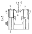
- the ultrasonic edge sensor shown in the drawing has a measuring head 100 shown in FIG. 1 alone in the form of an approximately U-shaped bracket with ultrasonic oscillators 102 arranged at the ends of the bracket legs 101, one of which is an ultrasonic transmitter, the other works as an ultrasound receiver. Both transducers 102 face each other mechanically across the measuring gap 103 formed between the bracket legs 101 and form a sound path between them, which is caused by the ultrasonic waves on their way from the ultrasonic transmitter to Ultrasound receiver is going through.
- a web 110 protrudes with its web edge 111 into the measuring gap 103. If the position of the web edge 111 changes in the width direction of the web (arrow 112), the ultrasonic waves in the sound path are more or less influenced, which is used for the detection of the edge position.
- the sound vibrators 102 have several, in the exemplary embodiment four ultrasonic sensors 1, 2, 3, 4 with a circular cross section, each of sensor transmitters 1.1, 2.1, 3.1, 4.1 and sensor receivers 1.2, 2.2, 3.2, 4.2 , wherein the sensor transmitters are arranged together in one, the sensor receivers together in the other of the two ultrasonic vibrators 102, and each sensor receiver 1.2, 2.2, 3.2, 4.2 faces the sensor transmitter 1.1, 2.1, 3.1, 4.1 assigned to it at the measuring gap 103.
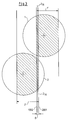
- the mutual arrangement of the sensors 1, 2, 3, 4 can be seen from FIG. 2.
- Each sensor is assigned its own measuring field 1 ', 2', 3 ', 4' in the sound path.
- the measurement field 1 ' is assigned to the outermost sensor 1 in the measurement gap 103, the measurement sensors 2 and 3' to the next sensors 2 and 3 and the measurement field 4 'to the innermost sensor 4.
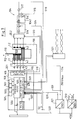
- the sensor transmitters 1.1, 2.1, 3.1, 4.1 (FIG. 4) each send out very short ultrasonic wave pulses.
- the assigned sensor receivers 1.2, 2.2, 3.2, 4.2 form electrical sensor signals from the ultrasonic wave pulses recorded in their measuring field 1 ', 2', 3 ', 4', depending on the degree of coverage of the measuring field 1 ', 2', 3 ', 4 'depend on the web 110.
- One, generally designated 20 in the drawing, operating as a multiplexer Switching device always switches on only one of the sensor transmitters 1.1 to 4.1 and only the associated sensor receiver 1.2 to 4.2, the sensor transmitter 1.1 to 4.1 being switched on by the switching part 20.1 and the sensor receiver 1.2 to 4.2 by the switching part 20.2.
- the switching device 20 with the two switching parts 20.1, 20.2 can be controlled for switching between the sensors 1 to 4, which will be described in detail.
- the peak value rectifier 104.1 can be activated or deactivated by a processor 105 via a line 104.3, so that it only works for a predetermined period of time from the time the ultrasonic wave pulse is received.
- processor 105 there is an arithmetic unit 106, which can be seen in more detail in FIG. 6 and calculates a sensor output signal S assigned to the edge position from the digitized reception signal W, which is used to control a web guide device (not shown) which, together with the edge sensor, forms a closed control circuit for forms the edge position of the web.
- a voltage generator 107 is provided for generating their transmitter voltage, in which the size of the transmitter voltage generated is adjustable and can be set to a calibration voltage specific to each sensor 1 to 4.
- the size of these calibration voltages is determined from the fact that each sensor 1 to 4, with its own calibration voltage, gives the same large reception signals W with a free measuring gap 103. Specifically, in an automatic adjustment run with completely free measuring gap 103, sensors 1 to 4 are switched through in sequence with switching parts 20.1 and 20.2 and the individual transmitter voltages for each sensor are changed until received signals W of the same size at the output of the A / D converter 104.2 result.
- the calibration voltages thus determined for the sensors are stored in a calibration data memory 108.
- the transmitter voltage is switched accordingly via a control line 109, so that each sensor is only ever operated with the calibration voltage assigned to it.
- the capacitance of all sensor transmitters 1.1 to 4.1 can be charged to the same transmitter voltage via a supply line 114, but this transmitter voltage must have the size of the calibration voltage of the current sensor. If you want to switch to another sensor, the transmitter voltage must first be changed to its calibration value.
- the sensor transmitters 1.1 to 4.1 are switched on in that the capacity of the current sensor transmitter is discharged by a booster 1.3 to 4.3 provided for each individual sensor transmitter and the ultrasonic wave pulse is thereby triggered.
- the Processor 105 uses lines 115 to generate a 5 microsecond pulse 128 (FIG. 8) for the respective booster 1.3 to 4.3.
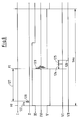
- the measuring field 1 'to 4' of each sensor 1 to 4 is delimited by two imaginary edge positions 1001, 1002, or 2001, 2002, or 3001, 3002 and 4001, 4002, which means more precisely that the sensors are only inside this limitation of their measuring field can be used for the measurement of current edge positions.
- the edge edge layers 1002, 2001 etc. of adjacent measuring fields 1 ', 2' or 2 ', 3' and 4 ' seem to coincide.
- the marginal edge positions overlap slightly, as is evident in the enlarged illustration in FIG. 3 using the example of the measuring fields 1 'and 2'.
- the overlap is labeled B.
- the received signal W has a maximum limit value Wmax in the right edge edge position 1001 to 4001, and a minimum limit value Wmin in the left edge edge position 1002 to 4002.
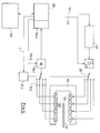
- the current position of the web edge 111 is always measured only by a single sensor 1 to 4, namely by the one in whose measuring field 1 'to 4' the strip edge 111 is located. If the band edge 111 moves from one measuring field to one of the two adjacent ones, the switching device 20 switches over to the corresponding other sensor. This changeover is controlled with the aid of a counter 116 counting up and down (FIG. 6), which has its own counter reading for each sensor 1 to 4, the sensors 1 to 4 being in the order of their measuring fields 1 'to 4 'given order are assigned to the meter readings.
- These counter readings correspond to four counter outputs 117, via which the counter 116 controls the switching device 20 so that the sensor assigned to the respective counter reading, that is to say the respective counter output 117, is switched on.
- the counter 116 is in turn controlled by a comparator circuit 118, which compares the value W of the received signal that results for a current edge position with the limit values Wmax and Wmin assigned to the edge positions of the switched on sensors 1 to 4. When the maximum limit Wmax is exceeded or the minimum limit Wmin is undershot, the counter 116 switches forward or backward to that Counter reading (outputs 117), which is assigned to the next sensor 1 to 4 in the sequence of the measuring fields 1 'to 4'.
- Digital calibration values S 1.1 , S 1.2 ... S k, n ..., S 4.6 for the sensor output signal S are also stored in the calibration data memory 108 for each calibration edge position.
- the assignment of these calibration values S k, n to the calibration edge positions z k, n depends on the dependency on the edge position desired for the sensor output signal, on its overall desired value range and / or on its desired zero point position, with a linear proportionality of the sensor output signal with the Edge position will be selected, but does not have to be selected.
- the arithmetic logic unit 106 calculates the value S of the current sensor output signal for the current edge position z k, n as a function of the switched-on sensor k, which results in the value S of the current sensor output signal, which is described in more detail later becomes.
- each calibration edge position z k, 6 (k 1 to 3), which lies within a measuring field overlap B, is assigned two calibration values for the received signal.
- These two calibration values W 1.6 , W 2.1 ; W 2.6 , W 3.1 ; W 3.6 , W 4.1 form, in addition to their function for calculating the current sensor output signal, in the exemplary embodiment Comparison variables with which the comparator circuit 118 compares the current received signal W, depending on the sensor that is switched on.
- the comparator circuit has a switching hysteresis so that the limit values Wmax, Wmin, which are relevant for sensor switching, differ from the calibration values by one hysteresis interval H each, i.e.
- the comparator circuit 118 has only two comparator units 118.1, 118.2, each with two inputs and one output. The one input of each comparator unit 118.1, 118.2 at the top in FIG. 6 is acted upon by the current received signal W.
- One of the two calibration values W k, n and W k, n + 1 of the received signal from the calibration data memory 108 can be connected to the other input.
- the outputs of the two comparator units 118.1 and 118.2 are linked via gate modules 119.1, 119.2, of which the gate module 119.1 resets the counter 116 and the other gate module 119.2 presents when the current received signal W is greater than or less than the smaller of the two each of the calibration values W k, n , W k, n + 1 applied .
- Another gate module 119.3 which links the outputs of the comparator units 118.1, 118.2, generates a signal which enables the arithmetic logic unit 106 when the current received signal W is applied in the interval between the two Calibration values W k, n , W k, n + 1 and therefore the current sensor output signal can be calculated with these calibration values.
- the counter 116 has an up / down counter 116.1 switched directly by the gate modules 119.1, 119.2 and a second up / down counter 116.2 switched thereby.
- the second counter 116.2 has as many, namely four counter readings as there are sensors and controls the switching device 20 with its counter readings via the outputs 117 and the line C in the manner already described, which is shown in FIG. 4 by switching an address decoder 20.3 in 7 takes place via line 510.
- the first counter 116.1 resets itself when the counter reading limits are exceeded in one direction or the other via a reset R and switches the second counter 116.2 back or forward by one counter reading each.
- both counters 116.1, 116.2 control with their respective counter readings via lines 121 an address decoder contained in the calibration data memory 108, not shown in FIG. 6, for calling up the calibration values W k, n , S belonging to the switched-on sensor k and to the calibration edge position z k, n k, n into a buffer 120.
- This calculation is carried out in the arithmetic logic unit 106. It has a subtractor 106.1 to which the current received signal W and the calibration value W k, n are fed from the buffer 120. The difference W k, n - W formed in the subtractor 106.1 is multiplied together with the calibration value m k, n for the proportionality factor taken from the buffer 120 in a multiplier 106.2 and the product with the calibration value S k, n from the buffer in an adder 106.3 adds what results in the current sensor signal S.
- the edge position of the web is measured in repetitive measuring cycles of 1 ms duration.
- the time diagram for such a measuring cycle is shown in FIG. 8.
- the transmitter voltage for the current sensor is first set, for which the duration of the time period 122 (350 ⁇ s) is available, the current sensor address is also set (row III) and with the BLANK signal (row V) the current sensor receiver is switched off.
- the current sensor transmitter is acted upon by the Dirac pulse 128 of 5 us duration, so that it emits an ultrasonic wave pulse and the sound propagation time begins.
- Delay span 127 which depends on the width of the measuring gap 103 in the measuring head 100 and is correspondingly adjustable when the gap width changes.
- the conversion of the (analog) electrical sensor signal into the digital received signal starts after a delay span 124 (about 80 microseconds), which after a further period 125 (about 37 microseconds) has ended, so that the determination of the current sensor output signal by the arithmetic logic unit 106 then begins with the pulse 126 (row VII).
- the sensor address valid for the next measuring cycle is determined and the next measuring cycle is started after the cycle duration of 1 ms.
- a reset clock generator 501 generates the switch-on reset on the one hand and the central clock at 16 MHz on the other.
- a program memory 502 contains the control program.
- a data memory 503 contains temporarily valid data and a copy of the calibration data saved in the calibration data memory 108.
- This calibration data memory 108 is designed as an EEPROM; In addition to the calibration values W k, n , S k, n , m k, n , the calibration voltages determined in the adjustment run are also stored there. It also contains key data required for operation, such as device and group addresses. The data are retained in the event of a power failure.
- a multifunction display 505 (yellow LEDs) Depending on the operating state, either the device and group address or, normalized to the entire measuring range of the edge sensor, shows the current position of the goods edge in the measuring gap of the measuring head 100.
- the brightness of the display can be influenced with an LED Control 506. Being able to switch off the LEDs in particular is particularly important when using the edge sensor on light-sensitive goods.
- the operating temperature is continuously measured with the temperature sensor 507 in order to be able to adapt the measuring time t1 (FIG. 8) to the variable sound propagation time.
- Multi-function buttons 508 are used in accordance with the current operating state to e.g. B. set the device and group address or emit signals that cause a shift of the web.
- a CAN bus indicator 509 supplies the status of the CAN transmission online.
- Processor 105 activates the current sensor via lines 510.
- the analog multiplexer 20.2 connects the sensor receiver channel selected by the current address to the preamplifier 514.
- the amplification of this two-stage preamplifier 514 can be selected via line 504 in order to enable adaptation to different-sized received signals, depending on the width of measuring gap 103.
- a CLEAR signal on line 515 discharges the capacitor 516 of the peak rectifier 104.1 until the next sound wave signal arrives.
- the impedance converter 517 with high input and low output impedance prevents feedback effects of the processor input on the charging capacitor 516 of the peak value rectifier 104.1, which could otherwise take place via the line 518 carrying the conditioned analog sensor signal.
- the target voltage of the Voltage generator 107 for the current sensor is set via control line 109 with a pulse width modulated signal from processor 105.
- the current voltage is measured and monitored by the processor 105 via the line 109 '.
- the power supply for the logic and analog part is designated 519.
- the processor 105 (80 C 592) has an integrated CAN bus controller 520, the input and output signals from and to the external CAN bus are received or sent via a CAN driver 521.
- the processor monitors supply voltage over line 522.
Landscapes
- Physics & Mathematics (AREA)
- General Physics & Mathematics (AREA)
- Length Measuring Devices With Unspecified Measuring Means (AREA)
Applications Claiming Priority (2)
| Application Number | Priority Date | Filing Date | Title |
|---|---|---|---|
| DE19500822 | 1995-01-13 | ||
| DE19500822A DE19500822C1 (de) | 1995-01-13 | 1995-01-13 | Ultraschall-Kantenfühler zur Erfassung der Bahnkante einer Warenbahn |
Publications (3)
| Publication Number | Publication Date |
|---|---|
| EP0721907A2 true EP0721907A2 (fr) | 1996-07-17 |
| EP0721907A3 EP0721907A3 (fr) | 1997-05-14 |
| EP0721907B1 EP0721907B1 (fr) | 2000-05-10 |
Family
ID=7751408
Family Applications (1)
| Application Number | Title | Priority Date | Filing Date |
|---|---|---|---|
| EP95119889A Expired - Lifetime EP0721907B1 (fr) | 1995-01-13 | 1995-12-16 | Détecteur de bord par ultra-sons pour la détection du bord d'une bande de matière |
Country Status (3)
| Country | Link |
|---|---|
| US (1) | US5803334A (fr) |
| EP (1) | EP0721907B1 (fr) |
| DE (2) | DE19500822C1 (fr) |
Cited By (1)
| Publication number | Priority date | Publication date | Assignee | Title |
|---|---|---|---|---|
| WO2011017816A3 (fr) * | 2009-08-14 | 2011-04-07 | Maschinenfabrik Rieter Ag | Surveillance et commande du guidage d'une courroie sur un dispositif d'enroulement |
Families Citing this family (32)
| Publication number | Priority date | Publication date | Assignee | Title |
|---|---|---|---|---|
| US6199198B1 (en) * | 1997-12-10 | 2001-03-06 | International Business Machines Corp. | Computer system, method, and article of manufacture for visualizing differences between design artifacts and object-oriented code |
| DE19941728B4 (de) * | 1998-10-08 | 2012-11-29 | Heidelberger Druckmaschinen Ag | Bogenkantendetektor |
| US6289729B1 (en) * | 1998-12-28 | 2001-09-18 | Fife Corporation | Ultrasonic sensor for web-guiding apparatus |
| US6175419B1 (en) * | 1999-03-24 | 2001-01-16 | Fife Corporation | Light sensor for web-guiding apparatus |
| DE19924798C1 (de) * | 1999-05-29 | 2001-01-11 | Erhardt & Leimer Gmbh | Verfahren und Vorrichtung zur Lageerfassung einer Kante von einer laufenden Warenbahn |
| US6566670B1 (en) | 2000-04-13 | 2003-05-20 | Accuweb, Inc. | Method and system for guiding a web of moving material |
| US6989118B2 (en) * | 2002-01-15 | 2006-01-24 | Kimberly-Clark Worldwide, Inc. | Process for making a reinforced fibrous absorbent member |
| US7745687B2 (en) * | 2002-01-15 | 2010-06-29 | Kimberly-Clark Worldwide, Inc. | Absorbent article with reinforced absorbent structure |
| US6802834B2 (en) | 2002-01-15 | 2004-10-12 | Kimberly-Clark Worldwide, Inc. | Absorbent article having discontinuous absorbent core |
| US6982052B2 (en) * | 2002-09-26 | 2006-01-03 | Kimberly-Clark Worldwide, Inc. | Process and apparatus for air forming an article having a plurality of superimposed fibrous layers |
| US20040102751A1 (en) * | 2002-11-27 | 2004-05-27 | Kimberly-Clark Worldwide, Inc. | Absorbent article with reinforced absorbent structure |
| US6981297B2 (en) | 2002-11-27 | 2006-01-03 | Kimberly-Clark Worldwide, Inc. | Controlled placement of a reinforcing web within a fibrous absorbent |
| JP4134911B2 (ja) * | 2003-02-27 | 2008-08-20 | 株式会社村田製作所 | 超音波送受波器、及びその製造方法 |
| US7345004B2 (en) * | 2003-07-15 | 2008-03-18 | Kimberly-Clark Worldwide, Inc. | Scrim reinforced absorbent article with reduced stiffness |
| US7594906B2 (en) | 2003-07-15 | 2009-09-29 | Kimberly-Clark Worldwide, Inc. | Absorbent article having a stretchable reinforcement member |
| US7415881B2 (en) * | 2004-08-19 | 2008-08-26 | Fife Corporation | Ultrasonic sensor system for web-guiding apparatus |
| US7615954B1 (en) * | 2005-01-05 | 2009-11-10 | Metropolitan Industries, Inc. | Density sensing, solid state, pump switching system |
| DE102005003166B4 (de) * | 2005-01-21 | 2012-01-26 | Baldwin Germany Gmbh | Waschvorrichtung für eine Druckmaschine |
| DE102008056458A1 (de) * | 2007-11-07 | 2009-07-23 | Cedes Ag | System zur Festellung eines Objekts in einer Überwachungsfläche |
| US8275506B1 (en) | 2008-06-08 | 2012-09-25 | Richard Anthony Bishel | Boundary sensor |
| DE202011002054U1 (de) | 2011-01-28 | 2011-05-26 | Texmag Gmbh Vertriebsgesellschaft | Ultraschall-Kantensensor |
| EP2546601B1 (fr) | 2011-07-15 | 2016-09-28 | microsonic GmbH | Dispositif de contrôle sans contact de la position des bords d'objets plats |
| EP2581723A3 (fr) | 2011-09-30 | 2015-04-22 | SONOTEC Dr. zur Horst-Meyer und Münch OHG | Dispositif et procédé de contrôle d'étanchéité de joints, notamment entre des cadres de porte ou fenêtre ouverts et construction de mur sur des bâtiments |
| SG11201402875TA (en) * | 2011-12-15 | 2014-07-30 | 3M Innovative Properties Co | Apparatus for guiding a moving web |
| DE202012004305U1 (de) * | 2012-04-27 | 2012-05-25 | Texmag Gmbh Vertriebsgesellschaft | Vorrichtung zum Detektieren einer Kante einer Materialbahn |
| US9415963B2 (en) | 2013-01-30 | 2016-08-16 | Fife Corporation | Sensor controller for interpreting natural interaction sensor for web handling |
| IT201700042506A1 (it) * | 2017-04-18 | 2018-10-18 | Btsr Int Spa | Metodo, sistema e sensore per rilevare una caratteristica di un filo tessile o metallico alimentato ad una macchina operatrice |
| CN107764191A (zh) * | 2017-11-15 | 2018-03-06 | 嘉兴扬鑫机械有限公司 | 探边器、探边方法及拉宽机 |
| JP7081143B2 (ja) * | 2017-12-27 | 2022-06-07 | セイコーエプソン株式会社 | 超音波装置、及び超音波測定方法 |
| JP2021043012A (ja) * | 2019-09-09 | 2021-03-18 | キオクシア株式会社 | 検査装置 |
| JP7756935B2 (ja) * | 2023-06-21 | 2025-10-21 | 株式会社マシンテックス | ウェブガイド装置、ウェブ幅計測方法、及びウェブ幅計測プログラム |
| CN116608801A (zh) * | 2023-07-20 | 2023-08-18 | 钛玛科(北京)工业科技有限公司 | 一种材料边缘位置检测系统和方法 |
Citations (2)
| Publication number | Priority date | Publication date | Assignee | Title |
|---|---|---|---|---|
| DE3442154C2 (fr) | 1984-11-17 | 1989-08-31 | Elektro-Mechanik Gmbh, 5963 Wenden, De | |
| US5072414A (en) | 1989-07-31 | 1991-12-10 | Accuweb, Inc. | Ultrasonic web edge detection method and apparatus |
Family Cites Families (4)
| Publication number | Priority date | Publication date | Assignee | Title |
|---|---|---|---|---|
| US3570624A (en) * | 1966-06-27 | 1971-03-16 | Lummus Co | Web tracking and control |
| US5274573A (en) * | 1989-07-31 | 1993-12-28 | Accuweb, Inc. | Ultrasonic web edge detection method and apparatus |
| US5027993A (en) * | 1989-08-14 | 1991-07-02 | Precision Handling Devices, Inc. | Perforated paper feed apparatus with an optical system for detecting the presence and/or motion of the paper |
| US4963807A (en) * | 1990-02-06 | 1990-10-16 | Zip-Pak Incorporated | Ultrasonic web edge guide circuit |
-
1995
- 1995-01-13 DE DE19500822A patent/DE19500822C1/de not_active Expired - Fee Related
- 1995-12-16 DE DE59508315T patent/DE59508315D1/de not_active Expired - Lifetime
- 1995-12-16 EP EP95119889A patent/EP0721907B1/fr not_active Expired - Lifetime
-
1996
- 1996-01-05 US US08/583,231 patent/US5803334A/en not_active Expired - Lifetime
Patent Citations (2)
| Publication number | Priority date | Publication date | Assignee | Title |
|---|---|---|---|---|
| DE3442154C2 (fr) | 1984-11-17 | 1989-08-31 | Elektro-Mechanik Gmbh, 5963 Wenden, De | |
| US5072414A (en) | 1989-07-31 | 1991-12-10 | Accuweb, Inc. | Ultrasonic web edge detection method and apparatus |
Cited By (2)
| Publication number | Priority date | Publication date | Assignee | Title |
|---|---|---|---|---|
| WO2011017816A3 (fr) * | 2009-08-14 | 2011-04-07 | Maschinenfabrik Rieter Ag | Surveillance et commande du guidage d'une courroie sur un dispositif d'enroulement |
| CN102471949A (zh) * | 2009-08-14 | 2012-05-23 | 里特机械公司 | 在卷绕装置中监测和控制皮带导向机构 |
Also Published As
| Publication number | Publication date |
|---|---|
| EP0721907B1 (fr) | 2000-05-10 |
| US5803334A (en) | 1998-09-08 |
| DE59508315D1 (de) | 2000-06-15 |
| DE19500822C1 (de) | 1996-03-21 |
| EP0721907A3 (fr) | 1997-05-14 |
Similar Documents
| Publication | Publication Date | Title |
|---|---|---|
| DE19500822C1 (de) | Ultraschall-Kantenfühler zur Erfassung der Bahnkante einer Warenbahn | |
| EP0970390B1 (fr) | Procede de determination de l'ecart vertical entre un objet et un dispositif a position variable | |
| DE2832835C2 (de) | Ultraschall-Meßanordnung | |
| DE4032713C2 (de) | Ultraschallsensor zur Hinderniserfassung | |
| EP0326623B1 (fr) | Procédé pour détecter la position d'un obstacle | |
| EP0753717B1 (fr) | Méthode et appareil pour mesurer les coordonnées de pièces usinées | |
| DE4223346C2 (de) | Anordnung und Verfahren zur berührungslosen Füllstandmessung | |
| EP0269902B1 (fr) | Procédé et dispositif pour mesurer la distance entre deux objets, en particulier entre deux véhicules à moteur | |
| DE19501642B4 (de) | Verfahren zur berührungslosen Abstandsmessung | |
| EP1185881B1 (fr) | Dispositif telemetrique et procede pour le calibrage d'un dispositif telemetrique | |
| DE4213926A1 (de) | Elektronische kraftfahrzeugstossstange | |
| DE2649075B2 (de) | Verfahren und Anordnung zur Messung des Füllstandes in einem Behälter bzw. der Schüttguthöhe auf einem Lagerplatz | |
| EP0556574A2 (fr) | Procédé pour la mesure des coordonnées sur des ouvrages | |
| DE19540170C2 (de) | Verfahren und Anordnung zur Unterdrückung von Festzielechos bei der Abstandsmessung nach dem Impulslaufzeitprinzip | |
| DE69324417T2 (de) | Vorrichtung und Verfahren zur Koordinateneingabe und Oszillationsgenerator | |
| EP1969390A1 (fr) | Procede pour l'etalonnage d'un systeme de capteurs | |
| DE10307851A1 (de) | Verfahren und Gerät zum Aufspüren und zur Entfernungsmessung von Gegenständen | |
| DE2817247A1 (de) | Verfahren und einrichtung zum messen von entfernungen oder fuellhoehen durch echolotung in einem gasfoermigen medium mittels schallwellen | |
| DE2902507C3 (de) | Vorrichtung zur Erzeugung eines Bildes eines mittels Ultraschallwellen abgetasteten Untersuchungsobjekts | |
| DE3643715A1 (de) | Anordnung zur uebertragung von messwerten eines sensors | |
| DE1816137A1 (de) | Numerisches Steuergeraet fuer eine Werkzeugmaschine | |
| EP0475941B1 (fr) | Dispositif de detection de l'energie rayonnee par des elements electroluminescents a semi-conducteurs et utilisation dans une installation d'impression electrophotographique | |
| EP1801618A2 (fr) | Dispositif optoélectronique | |
| DE2511260B2 (de) | Schaltungsanordnung in einer Strickmaschine | |
| DE4033605C1 (fr) |
Legal Events
| Date | Code | Title | Description |
|---|---|---|---|
| PUAI | Public reference made under article 153(3) epc to a published international application that has entered the european phase |
Free format text: ORIGINAL CODE: 0009012 |
|
| AK | Designated contracting states |
Kind code of ref document: A2 Designated state(s): DE GB IT |
|
| PUAL | Search report despatched |
Free format text: ORIGINAL CODE: 0009013 |
|
| AK | Designated contracting states |
Kind code of ref document: A3 Designated state(s): DE GB IT |
|
| 17P | Request for examination filed |
Effective date: 19970517 |
|
| GRAG | Despatch of communication of intention to grant |
Free format text: ORIGINAL CODE: EPIDOS AGRA |
|
| GRAG | Despatch of communication of intention to grant |
Free format text: ORIGINAL CODE: EPIDOS AGRA |
|
| GRAH | Despatch of communication of intention to grant a patent |
Free format text: ORIGINAL CODE: EPIDOS IGRA |
|
| 17Q | First examination report despatched |
Effective date: 19990914 |
|
| GRAH | Despatch of communication of intention to grant a patent |
Free format text: ORIGINAL CODE: EPIDOS IGRA |
|
| GRAA | (expected) grant |
Free format text: ORIGINAL CODE: 0009210 |
|
| AK | Designated contracting states |
Kind code of ref document: B1 Designated state(s): DE GB IT |
|
| ITF | It: translation for a ep patent filed | ||
| REF | Corresponds to: |
Ref document number: 59508315 Country of ref document: DE Date of ref document: 20000615 |
|
| GBT | Gb: translation of ep patent filed (gb section 77(6)(a)/1977) |
Effective date: 20000725 |
|
| EN | Fr: translation not filed | ||
| PLBE | No opposition filed within time limit |
Free format text: ORIGINAL CODE: 0009261 |
|
| STAA | Information on the status of an ep patent application or granted ep patent |
Free format text: STATUS: NO OPPOSITION FILED WITHIN TIME LIMIT |
|
| 26N | No opposition filed | ||
| REG | Reference to a national code |
Ref country code: GB Ref legal event code: IF02 |
|
| PGFP | Annual fee paid to national office [announced via postgrant information from national office to epo] |
Ref country code: GB Payment date: 20141216 Year of fee payment: 20 |
|
| PGFP | Annual fee paid to national office [announced via postgrant information from national office to epo] |
Ref country code: IT Payment date: 20141219 Year of fee payment: 20 |
|
| PGFP | Annual fee paid to national office [announced via postgrant information from national office to epo] |
Ref country code: DE Payment date: 20150211 Year of fee payment: 20 |
|
| REG | Reference to a national code |
Ref country code: DE Ref legal event code: R071 Ref document number: 59508315 Country of ref document: DE |
|
| REG | Reference to a national code |
Ref country code: GB Ref legal event code: PE20 Expiry date: 20151215 |
|
| PG25 | Lapsed in a contracting state [announced via postgrant information from national office to epo] |
Ref country code: GB Free format text: LAPSE BECAUSE OF EXPIRATION OF PROTECTION Effective date: 20151215 |