EP0721909A1 - Dispositif pour le positionnement contrÔlé de bobines dans une station d'une machine pour le bobinage automatique de bobines coniques - Google Patents
Dispositif pour le positionnement contrÔlé de bobines dans une station d'une machine pour le bobinage automatique de bobines coniques Download PDFInfo
- Publication number
- EP0721909A1 EP0721909A1 EP96200024A EP96200024A EP0721909A1 EP 0721909 A1 EP0721909 A1 EP 0721909A1 EP 96200024 A EP96200024 A EP 96200024A EP 96200024 A EP96200024 A EP 96200024A EP 0721909 A1 EP0721909 A1 EP 0721909A1
- Authority
- EP
- European Patent Office
- Prior art keywords
- coning
- spool
- spools
- carrier disk
- positioning
- Prior art date
- Legal status (The legal status is an assumption and is not a legal conclusion. Google has not performed a legal analysis and makes no representation as to the accuracy of the status listed.)
- Withdrawn
Links
Images


Classifications
-
- B—PERFORMING OPERATIONS; TRANSPORTING
- B65—CONVEYING; PACKING; STORING; HANDLING THIN OR FILAMENTARY MATERIAL
- B65H—HANDLING THIN OR FILAMENTARY MATERIAL, e.g. SHEETS, WEBS, CABLES
- B65H67/00—Replacing or removing cores, receptacles, or completed packages at paying-out, winding, or depositing stations
- B65H67/02—Arrangements for removing spent cores or receptacles and replacing by supply packages at paying-out stations
-
- B—PERFORMING OPERATIONS; TRANSPORTING
- B65—CONVEYING; PACKING; STORING; HANDLING THIN OR FILAMENTARY MATERIAL
- B65G—TRANSPORT OR STORAGE DEVICES, e.g. CONVEYORS FOR LOADING OR TIPPING, SHOP CONVEYOR SYSTEMS OR PNEUMATIC TUBE CONVEYORS
- B65G2201/00—Indexing codes relating to handling devices, e.g. conveyors, characterised by the type of product or load being conveyed or handled
- B65G2201/02—Articles
- B65G2201/0235—Containers
- B65G2201/0261—Puck as article support
-
- B—PERFORMING OPERATIONS; TRANSPORTING
- B65—CONVEYING; PACKING; STORING; HANDLING THIN OR FILAMENTARY MATERIAL
- B65H—HANDLING THIN OR FILAMENTARY MATERIAL, e.g. SHEETS, WEBS, CABLES
- B65H2701/00—Handled material; Storage means
- B65H2701/30—Handled filamentary material
- B65H2701/31—Textiles threads or artificial strands of filaments
Definitions
- the present invention relates to the manufacture of high quality threads by means of the combined spinning-coning process.
- the thread is produced and in the second step said thread is coned or rewound in order to deprive the thread of possible faulty or irregular portions from both viewpoints of aesthetical characteristics and mechanical strength, thus yielding a high-quality product.
- the spools produced by the spinning step are prearranged with their thread end at a predetermined position, in general with said thread end slid inside the upper bore of the tube on which the thread is wound to form the cop.
- the automatic coning unit will thus be capable of automatically catching said thread end from the spools as these are fed to it, and of starting the coning thereof, thus continuing the production of the cones.
- each coning station is capable of processing thirty, or even more, spools per hour, so that the total number of spools to be handled can be as large as some thousand pieces per hour.
- Such a handling volume requirement is very burdensome and in the most modern facilities it is committed, as far as possible, to automatic devices, with the interventions by the attending operators being only reserved to supervision and malfunctioning addressing.
- a general technical concept of automatic coning machines which was considerably successful, provides for the spools being positioned and transferred onto spool carrier means provided with a central, vertical pin, and keeping them standing on said carriers also during the preparation and unwinding steps, e.g., according to as taught by Japanese patent JP-A-49-12,128, Kanebo, or German patents 3,213,253; 3,249,583 and 3,235,442; Murata.
- spools Such a contrivance makes it possible the spools to be transferred and processed practically without being touched by any operators, and with only said carriers --generally having the nature of spool carrier disk means of circular shape -- having to be handled. Furthermore, the spool type can be identified by means of instrumental means, when a plurality of thread batches are being processed simultaneously, from the spool carrier disk means on which said spool is supported.
- the coming step is carried out at extremely high unwinding speeds.
- the upper cone revolves at so high speeds, that it unwinds the thread from the underlying cop at speeds of the order of 25 metres per second, or even higher.
- the underlying spool is just slid onto the pin of the spool disk carrer means which supports it, and rests standing on a support plane. Owing to the traction applied by the overhanging spool, the thred turns wound on the tube to form the cop, get unwound from it vortically whirling at speeds of the order of 15,000 rpm, forming a ballon around the spool with a non-negligible radial stress.
- the present invention relates to an apparatus for positioning the spools borne by said spool carrier disk means and keeping them properly positioned during the handling steps said spools are submitted to at the coning stations in order to move them between their stand-by, cop unwinding and exhausted spool tube discharging positions.
- the purpose of the present invention is of providing an improved device for conveying and handling the spools and tubes supported on spool carrier disk means, which is free from the drawbacks displayed by the analogous devices and processes known from the prior art.
- the spool carrier disk means (1) is constituted by a circular base (2), and a spool supporting shaft constituted by a collar (3), on which the tube of the spool to be conveyed rests, and a pin (4) which engages the bottom bore of the tube (5) of the spool.
- the diameter of the collar (3) is consequently substantially larger than of the tube, and the diameter of the pin (4) is slightly smaller than the diameter of the bore of the tube (5), so as to constrain said tube to stand in vertical position on said pin.
- the carrier disk means destined to support the spools to transport them are made from materials, and with such a finish degree of their bottom base, as to secure that said bottom base will display low adhesion to the flat surfaces onto which it comes to rest, so that it can be caused to slide on said surfaces by means of a very small force applied.
- the spool to be unwound is positioned on a spool carrier disk by means of per se known devices and methods.
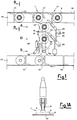
- a conveyor system In the scheme illustrated in Figure 1, facing each coning station installed on the machine front, a conveyor system circulates along a path (11) on which the spool carrier disk means (1) bearing the prepared spools ready to be unwound, are circulated, waiting for being diverted and fed towards the coning stations in such a need, on request by the latter.
- a conveyor system can be constituted by a conveyor belt, or another type of transport means, as, e.g., a thrust type of transport means with brackets (13) borne by a belt (12), which travels from the left to the right, on the plane of the drawing, pushing the spool carrier disk means (1) with their spools to run along the support plane (14).
- the full spool feed loop is preferably kept continuously moving and with its transport positions occupied by prepared spools ready to be unwound, so as to meet very rapidly the requests for spools from the coning stations, and constitute a reserve, or magazine, of cops, to meet any request peaks.
- the path (11) has, on its inner side towards said station, a branch (16) and a diverting organ constituted by a pin or blade (17), which can be commanded to protrude as an obstacle hindering the passage of the spool carrier disk means along the support surface (14), with said diverting organ being commanded by means of a drive means of conventional type not indicated in figure, following a request for a spool sent by the overhanging winding unit.
- the spool carrier disk means Owing to the combined effect of the push applied by the bracket (13), which continues to move rightwards, and of the hindrance constituted by the blade (17), the spool carrier disk means is pushed to move towards the winding station running along a portion of circular trajectory relatively to the end of the blade (17), until it gets disengaged from the push applied by the bracket (13) and reaches the stand-by position (A) along the straight path of the spools inside the interior of the winding station.
- a sensor means not indicated in figure, signals the event and commands the diverting blade (17) getting released in order to return to its resting position.
- the spool is caused to move along a linear path, not necessarily a straight one, as indicated in the figures.
- the spool processing path inside the coning station is realized on a support plane (18), preferably coplanar with the support plane (14) of the loop (11). It is bound by fixed guides (19) and is provided with pushing means to handle the spool disk carrier means.
- said guides (19) are installed in such a way as to lay above the base (2) of the spool carrier disk means and are arranged at a distance from the support plane (18) which is just slightly larger than the thickness of the base (2) of the spool carrier disk means, and at a mutual cross distance which is just slightly larger than the diameter of the collar (3).
- the processing path of the coning station contains at least three working positions.
- a first position referred to as the "(A) position” is the position reached by the spool as soon as it is delivered by the transport system and waiting for being brought to the unwinding step, which takes place at the second position, i.e., the "(D) position".
- the unwound spool which by now does no longer contain its cop, or which cannot be further unwound, is brought to the "(S) position" in order to be discharged to the conveyor system designed to handle the exhausted ("empty") spools.
- a spool in stand-by state is displayed, with its thread end (31) placed inside the top bore of the tube.
- the reference numeral (33) indicates the suction mouth for spool thread end catching, in its position (33A) in which said suction mouth delivers the thread to the suction mouth of the knotting device, and in its position (33B) in which said suction mouth takes the thread end from the spool (32).
- the sensor for thread presence on the spool side is indicated with (34) and the thread tightener is indicated with (35).
- the reference numeral (36) indicates the thread end suction mouth of the knotting device on the spool side, in its position (36A) in which it delivers the thread end to the knotting device (37), and in its position (36B) in which it takes the thread end from the suction mouth (33).
- the slub catcher is indicated with (38) and (39) is the suction mouth for the thread end from the cone (40), in its positions (39A) in which it catches the thread end from the cone and (39B) in which it delivers said thread end to the knotting device (37).
- the cone drive roller is indicated with (41) and the cone carrier arm is indicated with (42).
- the trajectory (43) of the thread between the spool and the cone is indicated in chain line.
- the handling of the spools between (A), (D) and (S) positions is determined by commands sent by the coning station.
- the spool which is being unwound (32) is regarded as being exhausted by the organs of the coning machine, either because it was completely unwound, or because a certain number of attempts of thread end search, catching and knotting were unsuccessful: in that case, the coning machine pilot unit commands the change of the spool which is being unwound.
- the command of unwound spool change is then integrated by the pilot unit with both the command for calling a new reserve spool from its stand-by position (A), which got liberated during the spool change, and the command for exhausted spool discharge.
- the call for the new spool is implemented by causing the diverting blade (17) to move upwards.
- the exhausted spool which is in (S) position must be removed at once in order to let said position free; said removal must take place on the first signal of discharge path free.
- the motion of the spools inside the interior of the coning station is caused to take place by a push action.
- the spools are caused to move by means of the pair of pushing levers (50) and (51), which pivot on the horizontal plane around the hinges (52) and (53), and are linked by the tie-rod (54). They are positioned above the guides (15) and are caused to pivot according to a limited revolutionary stroke in clockwise and counterclockwise directions alternatively, by the double acting hydraulic cylinder (55), e.g., pneumatically actuated with the compressed air from the machine air system.
- said levers (50) and (51) are realized -- at least as regards the lever (51) -- with their far ends relatively to hinges (52) and (53), respectively, being equipped with articulated joints which remain stiff when said levers urge downwards on drawing plane, i.e., towards the discharge path, the collar (3) of the spool carrier disk means with the spools on the plane of Figure 1, by being caused to revolve counterclockwise; and which, on the contrary, fold on themselves when, during their return movement back to their rest positions, said levers are caused to revolve clockwise and interfere with the obstacle constituted by the collar of the spool carrier disk carrying the new spool which is being unwound and, possibly, also constituted by the collar of the new spool in stand-by position. Said articulated joints return back to their extended position after overcoming said obstacles, owing to the action of a spring of conventional type, not indicated in figure.
- the conveyor system for the exhausted spools can be constituted by a conveyor tape or another type of transport system, e.g., a push transport system with brackets and a support plane.
- the step of delivering the exhausted spool to the transport system for the exhausted spools is commanded by the coning machine pilot unit.
- the removal takes place by means of a push lever system analogous to the preceding one and constituted by a push lever (61) which pivots around the hinge (62).
- Said push lever is caused to revolve according to a limited revolution stroke in clockwise and counterclockwise directions, by the double acting cylinder (63).
- the lever (61) is caused to return back to its rest position.
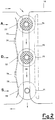
- Figure 2 illustrates, by referring to a typical embodiment thereof, the positioning system which secures the correct positioning of the spool carrier disk means.
- Said positioning system is one from the peculiar features of the technical solution according to the present invention.
- such a guide system is constituted by a fixed body (70) positioned on the right-hand side to the guides (19), and provided with hollows (71) corresponding to the above cited processing positions, in which the spool carrier disk means with its overhanging spool must be accurately positioned.
- a fixed body (70) positioned on the right-hand side to the guides (19)
- hollows (71) corresponding to the above cited processing positions, in which the spool carrier disk means with its overhanging spool must be accurately positioned.
- the shape of the hollow (71) is consistent with the curvature of the cylindrical base of the spool carrier disk means, so as to fit to it.
- a semi-elliptic spring (73) is installed, with convexities (73') protruding towards the hollows (71) and opposite to them.
- Such semi-elliptic springs (73) are fastened and adjusted relatively to the plane (18) by means of brackets (74), in such a way that said convexities (73') are facing said hollows (71).
- the spool carrier disk means is moved along the path bound by the guides (19) and owing to the effect of the stroke of levers (50)/(51) in vertical direction on the plane of the drawing of Figure 2, sliding along the straight portion of the face of the body (70).
- the cylindrical peripheral portion of the spool disk means finds the convexity (73') of the semi-elliptic spring (73)
- the stroke of the pushing levers (50)/(51) towards their stroke limit continues according to a slightly, but meaningfully diverted path, owing to the thrust applied by the semi-elliptic spring, towards the interior of the hollow (71), crosswise relatively to said path.
- the depth of the hollow (71) does not exceed the width of the room between the guides (19) exceeding the diameter of the collar (3) of the spool carrier disk means, i.e., is shorter than the difference between said dimensions.
- the fixed body (70) with its hollows (71) is provided to the left of the path of the guides (19), and the transversal pushing organ is installed to the right.
- the pushing organ for said spool carrier disk means inside said positioning hollows (71) is constituted by a slider (80) provided with guide means (not shown in the figure) which allow it to reciprocate transversally to the path defined by the guides (19).
- a slider (80) is urged leftwards by a spring (81) compression loaded against a fixed stop member (82), thus tending to urge the spool carrier disk means against the hollows (71).
- the slider (80) is provided with actuation hollows (83), (84).
- levers (50)/(51) are in their normal rest position, and the (A) position is occupied by a spool in stand-by position, ready to be processed; the (D) position is occupied by a spool which is being unwound, and the (S) position is free, waiting for receiving the spool disk carrier means bearing the empty tube.
- the levers (50)/(51) engage the hollows (83)/(84) with the low contour of the cams (85)/(86); therefore, said hollows (83)/(84) allow for spring (81) to shift the cursor (80) to the left -- thus taking its most outwards protruding configuration.
- Said slider pushes the spool carrier disk means to the left, and causes them to get engaged inside their respective hollow (71).
- Such an action of blockage of the spool carrier disk means with its spool counteracts and resists to the stresses which may be caused by the unwinding operation.
- the spool change is carried out by actuating the levers (50)/(51) with the pneumatic cylinder (55); the levers (50)/(51) rotate counterclockwise to push the spool carrier disk means downwards, as seen in Figure 5B.
- the levers (50)/(51) Upon rotating, the levers (50)/(51) cause the high portion of the contour of the cams (85)/(86) to come into engagement with the hollows (83)/(84); thus, they compress the spring (81) causing it to turn into its most compressed configuration, and cause the slider to move to the right.
- the slider liberates the spool disk carrier means, which can thus smoothly disengage from their respective hollow (71) under the thrust applied by the levers (50)/(51).
- the hollows (71) corresponding to the stand-by and discharge positions can be countersunk in the incoming and departure directions, respectively, so as to disengage in time the operations of feeding the new spool to the stand-by position of the coning station and of removal of the exhausted spool from the discharge position, from the action of spool carrier disk means blockage by the cams (85)/(86).
- the system according to the present invention for handling and positioning the spools along their processing path in the coning station offers considerable advantages over the systems known from the prior art. Among them, we regard the following as being worth being mentioned.
- the full spool feed loop can be kept continuously moving and with all, or most, of its transport positions being full with ready-to-unwind spools, so as to meet very rapidly the requests for spools coming from the coning stations, and to constitute a reserve (magazine) of ready-to-unwind spools for meeting request peaks.
- the presence of the upper guides (19) will secure that the spool carrier disk means will always remain resting on the support plane (18) and that the spool will always stand in vertical position, owing to the action of blocking the spool carrier disk means inside the hollows (71) of the fixed body (70) under the thrust applied by elastic means of semi-elliptic spring type (73), or by the slider (80).
- the support surface (18) can be provided with suitable openings for removing dirt and impurities developed during the unwinding step.
- the positioning system with elastic blockage allows the spool carrier disk means to counteract and withstand the stresses which may be applied by the unwinding operation of both hairy threads or irregularly wound threads.
Landscapes
- Replacing, Conveying, And Pick-Finding For Filamentary Materials (AREA)
- Replacement Of Web Rolls (AREA)
Applications Claiming Priority (2)
| Application Number | Priority Date | Filing Date | Title |
|---|---|---|---|
| ITMI950024A IT1272872B (it) | 1995-01-10 | 1995-01-10 | Dispositivo per il posizionamento controllato delle spole in una stazione di una roccatrice automatica |
| ITMI950024 | 1995-01-10 |
Publications (1)
| Publication Number | Publication Date |
|---|---|
| EP0721909A1 true EP0721909A1 (fr) | 1996-07-17 |
Family
ID=11370154
Family Applications (1)
| Application Number | Title | Priority Date | Filing Date |
|---|---|---|---|
| EP96200024A Withdrawn EP0721909A1 (fr) | 1995-01-10 | 1996-01-05 | Dispositif pour le positionnement contrÔlé de bobines dans une station d'une machine pour le bobinage automatique de bobines coniques |
Country Status (4)
| Country | Link |
|---|---|
| US (1) | US5683046A (fr) |
| EP (1) | EP0721909A1 (fr) |
| CN (1) | CN1138643A (fr) |
| IT (1) | IT1272872B (fr) |
Cited By (1)
| Publication number | Priority date | Publication date | Assignee | Title |
|---|---|---|---|---|
| EP0934898A3 (fr) * | 1998-02-05 | 2002-06-26 | W. SCHLAFHORST AG & CO. | Bobinoir |
Families Citing this family (6)
| Publication number | Priority date | Publication date | Assignee | Title |
|---|---|---|---|---|
| DE19910764B4 (de) * | 1999-03-11 | 2011-11-10 | Rieter Ingolstadt Gmbh | Verfahren und Vorrichtung zur Handhabung einer Leerhülse auf einer Textilmaschine |
| JP2018065644A (ja) * | 2016-10-18 | 2018-04-26 | 村田機械株式会社 | トレイ搬送装置、糸巻取設備、糸巻取システム、トレイ搬送装置の駆動方法、及び、糸巻取システムの起動方法 |
| DE102016013486B3 (de) * | 2016-11-11 | 2018-01-04 | Admedes Schuessler Gmbh | Flechtmaschine und Weiche für eine Flechtmaschine |
| CN109019171B (zh) * | 2018-08-31 | 2024-06-04 | 杭州锐冠科技有限公司 | 一种用于络筒机的自动抓纱装置 |
| CN109019172B (zh) * | 2018-08-31 | 2024-06-04 | 杭州锐冠科技有限公司 | 一种可自动抓纱的络筒机 |
| CN109693974B (zh) * | 2019-01-31 | 2023-08-08 | 南通宏泰机械制造有限公司 | 一种垂直式满纱提升装置 |
Citations (6)
| Publication number | Priority date | Publication date | Assignee | Title |
|---|---|---|---|---|
| DE3213253A1 (de) * | 1981-04-10 | 1982-10-28 | Murata Kikai K.K., Kyoto | Vorrichtung zum beliefern eines spulautomaten mit kopsen |
| DE3637172A1 (de) * | 1986-10-31 | 1988-05-05 | Schlafhorst & Co W | Verfahren und vorrichtung zum erhoehen der spulgeschwindigkeit eines spulautomaten |
| DE3810785A1 (de) * | 1988-03-30 | 1989-10-12 | Schlafhorst & Co W | Kopstraeger-transportsystem eines spulautomaten |
| JPH0252868A (ja) * | 1988-08-18 | 1990-02-22 | Murata Mach Ltd | トレイの移動制御装置 |
| DE4116555A1 (de) * | 1990-05-21 | 1991-11-28 | Murata Machinery Ltd | Foerdervorrichtung fuer garnlieferspulen in einer dubliereinrichtung |
| JPH0661471A (ja) * | 1992-06-18 | 1994-03-04 | Eastman Kodak Co | テスト構造を有するccdイメージャおよびccdイメージャのテスト方法 |
Family Cites Families (7)
| Publication number | Priority date | Publication date | Assignee | Title |
|---|---|---|---|---|
| DE3729130A1 (de) * | 1987-09-01 | 1989-03-09 | Schlafhorst & Co W | Einrichtung zum transport von kopsen und huelsen |
| JPH0780631B2 (ja) * | 1988-03-17 | 1995-08-30 | 村田機械株式会社 | 巻取方法 |
| DE4011797C2 (de) * | 1989-06-10 | 1998-02-12 | Schlafhorst & Co W | Transportsystem für eine automatische Textilmaschine zum gesteuerten Führen von Paletten entlang vorgegebener Transportwege |
| US5236142A (en) * | 1990-05-21 | 1993-08-17 | Murata Kikai Kabushiki Kaisha | Feed yarn package conveyor system in doubler |
| DE4019099A1 (de) * | 1990-06-15 | 1991-12-19 | Schlafhorst & Co W | Vorrichtung zum positionieren von auf unabhaengige einzeltraeger aufgesetzten spulen und drehen um deren laengsachse |
| DE4025003A1 (de) * | 1990-08-07 | 1992-02-13 | Schlafhorst & Co W | Kopsvorbereitungseinrichtung mit durch sensorsignale gesteuert vertikal lageveraenderbaren mitteln zum ansaugen des fadenanfanges von der kegeligen bewicklungsoberflaeche von kopsen |
| US5374000A (en) * | 1992-01-30 | 1994-12-20 | Murata Kikai Kabushiki Kaisha | Cop changing mechanism for a winding unit |
-
1995
- 1995-01-10 IT ITMI950024A patent/IT1272872B/it active IP Right Grant
-
1996
- 1996-01-05 US US08/583,442 patent/US5683046A/en not_active Expired - Fee Related
- 1996-01-05 EP EP96200024A patent/EP0721909A1/fr not_active Withdrawn
- 1996-01-09 CN CN96100842.3A patent/CN1138643A/zh active Pending
Patent Citations (6)
| Publication number | Priority date | Publication date | Assignee | Title |
|---|---|---|---|---|
| DE3213253A1 (de) * | 1981-04-10 | 1982-10-28 | Murata Kikai K.K., Kyoto | Vorrichtung zum beliefern eines spulautomaten mit kopsen |
| DE3637172A1 (de) * | 1986-10-31 | 1988-05-05 | Schlafhorst & Co W | Verfahren und vorrichtung zum erhoehen der spulgeschwindigkeit eines spulautomaten |
| DE3810785A1 (de) * | 1988-03-30 | 1989-10-12 | Schlafhorst & Co W | Kopstraeger-transportsystem eines spulautomaten |
| JPH0252868A (ja) * | 1988-08-18 | 1990-02-22 | Murata Mach Ltd | トレイの移動制御装置 |
| DE4116555A1 (de) * | 1990-05-21 | 1991-11-28 | Murata Machinery Ltd | Foerdervorrichtung fuer garnlieferspulen in einer dubliereinrichtung |
| JPH0661471A (ja) * | 1992-06-18 | 1994-03-04 | Eastman Kodak Co | テスト構造を有するccdイメージャおよびccdイメージャのテスト方法 |
Non-Patent Citations (2)
| Title |
|---|
| PATENT ABSTRACTS OF JAPAN vol. 14, no. 221 (M - 0971) 10 May 1990 (1990-05-10) * |
| PATENT ABSTRACTS OF JAPAN vol. 9, no. 198 (M - 404)<1921> 15 August 1985 (1985-08-15) * |
Cited By (1)
| Publication number | Priority date | Publication date | Assignee | Title |
|---|---|---|---|---|
| EP0934898A3 (fr) * | 1998-02-05 | 2002-06-26 | W. SCHLAFHORST AG & CO. | Bobinoir |
Also Published As
| Publication number | Publication date |
|---|---|
| CN1138643A (zh) | 1996-12-25 |
| IT1272872B (it) | 1997-07-01 |
| ITMI950024A0 (it) | 1995-01-10 |
| US5683046A (en) | 1997-11-04 |
| ITMI950024A1 (it) | 1996-07-10 |
Similar Documents
| Publication | Publication Date | Title |
|---|---|---|
| US5937629A (en) | Method and device for supplying empty tubes to winding devices of a textile machine | |
| US4865260A (en) | Equipment and process to supply winding tubes to the individual winding stations of a textile machine | |
| US3295775A (en) | Method and apparatus for readying the winding operation of yarn supply coils on coil winding machines | |
| CN101395079B (zh) | 用于取下卷筒的装置 | |
| CN101583551A (zh) | 用于卷绕长丝的装置 | |
| US3774859A (en) | Bobbin handling system | |
| US5515672A (en) | Transport system in a pot spinning machine | |
| EP0721910B1 (fr) | Dispositif pour la manipulation et la distribution de bobines aux stations d'une machine à bobiner les bobines | |
| US4613091A (en) | Cop transporting system for an automatic winder | |
| US3279710A (en) | Yarn-package winding machine with automatic coil exchanging and yarn tying devices | |
| US4451007A (en) | Yarn winding apparatus | |
| US4134559A (en) | Equipment for processing material in sheet or ribbon form | |
| US4742967A (en) | System for delivering packages to an automatic winder | |
| US5683046A (en) | System for positioning spools at a coning unit of an automatic coning machine | |
| EP0721911A1 (fr) | Dispositif pour la manipulation automatique de bobines dans une machine automatique de bobinage de bobines coniques | |
| EP1950163B1 (fr) | Tête de bobinage automatique | |
| EP1932793A2 (fr) | Dispositif et procédé de préparation de bobines pour alimenter un bobinoir automatique | |
| US20010004999A1 (en) | Interface in the transport system of a textile machine producing cross-wound bobbins | |
| US5423493A (en) | Method for operating an automatic bobbin-winding machine during batch changing operations | |
| US5207051A (en) | Apparatus for transferring full bobbins and empty bobbins between a bobbin winding machine and a transporting mechanism | |
| US6012670A (en) | Multiple dynamo-electric machine parts handling and winding methods and apparatus | |
| JP7530435B2 (ja) | ストックリールからタイヤ部品を巻き戻すための巻き戻しシステム、アセンブリ、および方法 | |
| US5343687A (en) | Winder-to-double twister connecting system | |
| US5289674A (en) | Winding machine with an in-line package preparer, and an improved spinning-winding method | |
| JP3513548B2 (ja) | 紡績機械 |
Legal Events
| Date | Code | Title | Description |
|---|---|---|---|
| PUAI | Public reference made under article 153(3) epc to a published international application that has entered the european phase |
Free format text: ORIGINAL CODE: 0009012 |
|
| AK | Designated contracting states |
Kind code of ref document: A1 Designated state(s): BE CH DE ES FR GB GR IE LI PT SE |
|
| 17P | Request for examination filed |
Effective date: 19961206 |
|
| 17Q | First examination report despatched |
Effective date: 19971118 |
|
| STAA | Information on the status of an ep patent application or granted ep patent |
Free format text: STATUS: THE APPLICATION IS DEEMED TO BE WITHDRAWN |
|
| 18D | Application deemed to be withdrawn |
Effective date: 19980331 |