EP0722023B1 - Aus Profilstäben gebildete miteinander verbundene Pfosten und Riegel - Google Patents
Aus Profilstäben gebildete miteinander verbundene Pfosten und Riegel Download PDFInfo
- Publication number
- EP0722023B1 EP0722023B1 EP95118405A EP95118405A EP0722023B1 EP 0722023 B1 EP0722023 B1 EP 0722023B1 EP 95118405 A EP95118405 A EP 95118405A EP 95118405 A EP95118405 A EP 95118405A EP 0722023 B1 EP0722023 B1 EP 0722023B1
- Authority
- EP
- European Patent Office
- Prior art keywords
- uprights
- upright
- connector
- crossbars
- crossbars according
- Prior art date
- Legal status (The legal status is an assumption and is not a legal conclusion. Google has not performed a legal analysis and makes no representation as to the accuracy of the status listed.)
- Expired - Lifetime
Links
- 239000011521 glass Substances 0.000 claims description 6
- 238000004080 punching Methods 0.000 claims description 3
- 238000000465 moulding Methods 0.000 abstract 1
- 238000010276 construction Methods 0.000 description 2
- 210000001503 joint Anatomy 0.000 description 2
- 238000010586 diagram Methods 0.000 description 1
- 239000002184 metal Substances 0.000 description 1
- 239000004575 stone Substances 0.000 description 1
Images


Classifications
-
- E—FIXED CONSTRUCTIONS
- E04—BUILDING
- E04B—GENERAL BUILDING CONSTRUCTIONS; WALLS, e.g. PARTITIONS; ROOFS; FLOORS; CEILINGS; INSULATION OR OTHER PROTECTION OF BUILDINGS
- E04B2/00—Walls, e.g. partitions, for buildings; Wall construction with regard to insulation; Connections specially adapted to walls
- E04B2/74—Removable non-load-bearing partitions; Partitions with a free upper edge
-
- E—FIXED CONSTRUCTIONS
- E04—BUILDING
- E04B—GENERAL BUILDING CONSTRUCTIONS; WALLS, e.g. PARTITIONS; ROOFS; FLOORS; CEILINGS; INSULATION OR OTHER PROTECTION OF BUILDINGS
- E04B2/00—Walls, e.g. partitions, for buildings; Wall construction with regard to insulation; Connections specially adapted to walls
- E04B2/88—Curtain walls
- E04B2/96—Curtain walls comprising panels attached to the structure through mullions or transoms
Definitions
- the invention relates to formed from profile bars by locking parts interconnected mullions and transoms on which facade elements can be fixed are.
- Such mullion-transom constructions are used on the outer walls of buildings attached to fix facade elements that match the external appearance give the building an attractive appearance.
- the facade elements can with provided window panes with uniform or different designs Glasses exist. It is also known, the infill between posts and transoms to be filled with sheet metal or stone.
- Bars are also known (EP-A-0 436 869, EP-A-0 375 089) which are used for connection are provided with a post profile with projecting bolts on the end face, so that each bolt must be moved in the direction of its longitudinal axis in order to form a positive To achieve connection with the post profile.
- the invention has for its object the mullion and transom of the generic type Art to design so that a connection between the post and transom without their additional Processing is possible and the latch between two already assembled Posts can be used.
- the latch is positioned in relation to the connector by means of a longitudinal groove then by the manually operated bolt catch in this positive locking position secured.
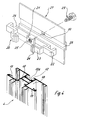
- FIG. 1 shows part of a facade of a building.
- the posts 4 and the bars 5 are by means of locking parts positive and / or non-positive with each other or with fixed frame parts 2 (Fig. 2) connected, these frame parts 2 form the boundary of a window 42, for example can.
- facade elements 41 for example in the form of glazing.
- the slide 6 has a hammer-shaped head 10, to a guide part 7 lying in the chamber 12 angled free end face has a profile 11, which positively engages in a frame groove 3 of the frame part 2.
- a pressure screw 16 arranged, for example by means of a screwdriver 17 can be screwed in so far that it is supported on the bottom of the frame groove 3 and thus a clamping the slide 6 reached.
- the guide part 7 In the end facing away from the head 10, the guide part 7 an elastic compensation piece 8, which in a receiving groove lies and the tolerances of the chamber 12 compensates so that a firm seat of the slider 6 in the chamber 12 ensures is.
- FIGS 4 to 8 are embodiments of locking parts shown, with the posts 4 and 5 bars together get connected.
- the width of the connector 20 corresponds to the width of one Longitudinal groove 13 of the bolt 5, so that the connector 20 against rotation is held in the longitudinal groove 13.
- the connector 20 also has a molded-on sliding block 21 on, which in an undercut longitudinal groove 13a of the post 4th is inserted and which has a threaded bore 25 in a punch pin screw 29 is screwed in.
- the two, which engage in the longitudinal grooves 13 of the associated bolts End regions of the connector 20 are as support parts 22 trained and are on the one hand at the bottom of the respective Longitudinal groove 13 and on the other hand in a guide groove 28 one Base plate 27 in which also a guide web 26 of the connector 20 lies, which carries the sliding block 21.
- the depth of the guide groove 28 corresponds to the thickness of the guide web 26, as can be seen particularly clearly from FIG. 5 is what is assigned to a common investment area Side of the post 4 results.
- the assembled unit consisting of the connector 20 and the base plate 27 and the punch 29 is according to the figure 5 pushed onto the post 4 and on a corresponding one Positioned by the punch screw 29.
- the punching shoulder of the punching screw 29 cuts into the ground the longitudinal groove 13a and thus forms a positive locking the connector in the longitudinal axis direction of the post 4.
- FIG. 5 clearly shows, extends the base plate 27 over the entire length of the connector 20, so that there is an aligned conclusion.
- an in Boom 23 extending in the direction of the slot nut 21, which has an angled nose 24, which is located on a profile web 19 of the post 4 supports.
- a gap is formed between the nose 24 and the arm 23, engages in the end of a bolt catch 30, which in a fitting guide groove 15 of the bolt 5 is guided.
- the latch 30 is adjacent to the gap as a latching hook 31 formed, which has a slope through which when inserted of the bar latch 30 the profiling of the post 4 is expanded slightly, the locking hook 31 after the Inserting the bar latch 30 the profiling of the post 4 engages behind, so that the latch catch 30 positively is fixed. This will ensure that the Bolt 5 guaranteed on post 4. It is essential that the Because of the fitting guide groove 15 with that assigned to the gap Side of the boom 23 is aligned so that the latch 30th itself both at the bottom of the fitting guide groove 15 and Boom 23 supports.
- connection according to the invention makes it possible to use a obtuse-cut bar 5 between two pre-assembled Use post 4.
- a latch 5 is on the one hand with a post 4 and on the other hand to connect with a frame part 2, so takes place first connect the latch 5 to the frame part 2 by the slide 6, corresponding to FIG. 2 or FIG. 3 and then the attachment to the post 4 by means of the latch 30th
- the base plate 27 ensures complete coverage of the Joint area between the bars 5 and the post 4, so that a tight butt joint is achieved. It is also through the Base plate 27 is given an anti-rotation lock 4.
- FIG. 8 Another embodiment variant of the invention is in the figure 8 shown.
- a connector 38 is used, which in its cross-sectional contour essentially the contour of the Glasfalzraumes 18 is adjusted so that it is positive lies in.
- Each connector 38 has the same as that already described Connector 20 is a support member 22, which is in this embodiment is supported on a profile web 37, which on the post 4th is molded.
- Each connector 38 is connected by means of a pressure screw 40 a punch is provided, which is in the bottom of the glass rebate 18 punched, fixed.
- a base plate 36 can be provided instead of the profile webs 37 be by means of the sliding block 21 which in the longitudinal groove 13a is defined, and which is both a facility for the Support parts 22 and the bolt 5 forms and at the same time the Joints between the bars 5 and the post 4 covers. With With the help of the clamping screw 39, the base plate 36 is fixed.
Landscapes
- Engineering & Computer Science (AREA)
- Architecture (AREA)
- Electromagnetism (AREA)
- Civil Engineering (AREA)
- Structural Engineering (AREA)
- Physics & Mathematics (AREA)
- Mutual Connection Of Rods And Tubes (AREA)
- Joining Of Building Structures In Genera (AREA)
- Load-Bearing And Curtain Walls (AREA)
- Revetment (AREA)
- Load-Engaging Elements For Cranes (AREA)
- Other Liquid Machine Or Engine Such As Wave Power Use (AREA)
- Mobile Radio Communication Systems (AREA)
- Measuring Pulse, Heart Rate, Blood Pressure Or Blood Flow (AREA)
- Paper (AREA)
- Containers, Films, And Cooling For Superconductive Devices (AREA)
- Rod-Shaped Construction Members (AREA)
Description
- Figur 1
- eine mit erfindungsgemäß miteinander verbundenen Pfosten und Riegeln versehene Fassade eines Gebäudes in schaubildlicher Darstellung;
- Figur 2
- den Verbindungsbereich eines Pfostens, bzw. eines Riegels am Blendrahmen eines Fensters in Explosivdarstellung;
- Figur 3
- einen Teilquerschnitt durch den Verbindungsbereich nach der Figur 2;
- Figur 4
- eine Einzelheit der Erfindung in Explosivdarstellung;
- Figur 5
- einen Teilschnitt durch einen Verbindungsbereich zwischen einem Pfosten und daran angeschlossenen Riegeln;
- Figur 6
- weitere Ausführungsbeispiele von Verbindungen zwischen Pfosten und Riegeln in schaubildlicher Darstellung;
- Figur 7
- einen Teilquerschnitt durch einen Verbindungsbereich gemäß der Figur 6;
- Figur 8
- ein weiteres Ausführungsbeispiel der Erfindung, dargestellt in einem Detailquerschnitt.
- 1
- Blendrahmen
- 2
- Rahmenteil
- 3
- Rahmennut
- 4
- Pfosten
- 5
- Riegel
- 6
- Schieber
- 7
- Führungsteil
- 8
- elast. Ausgleichsstück
- 9
- Aufnahmenut
- 10
- Kopf
- 11
- Profilierung
- 12
- Kammer
- 13
- Längsnut
- 13a
- Längsnut
- 14
- Anlagefläche
- 15
- Beschlagführungsnut
- 16
- Druckschraube
- 17
- Schraubendreher
- 18
- Glasfalzraum
- 19
- Profilsteg
- 20
- Verbinder
- 21
- Nutstein
- 22
- Stütztteil
- 23
- Ausleger
- 24
- Nase
- 25
- Gewindebohrung
- 26
- Führungssteg
- 27
- Grundplatte
- 28
- Führungsnut
- 29
- Stanzschraube
- 30
- Riegelschnäpper
- 31
- Rasthaken
- 32
- Grifflasche
- 33
- Verbinder
- 34
- Grundplatte
- 35
- Ansatz
- 36
- Grundplatte
- 37
- Profilsteg
- 38
- Verbinder
- 39
- Klemmschraube
- 40
- Druckschraube
- 41
- Fassadenelement
- 42
- Fenster
Claims (16)
- Aus Profilstäben gebildete, durch Verriegelungsteile miteinander verbundene Pfosten und Riegel, an denen Fassadenelemente festlegbar sind, dadurch gekennzeichnet, daß die Verriegelungsteile aus einem Verbinder (20,33,38) und einem Riegelschnäpper (30) bestehen, wobei der Verbinder (20,33,38) am Pfosten (4) befestigt ist und der Riegelschnäpper (30) im Riegel (5) formschlüssig geführt und korrespondierend mit dem Verbinder (20,33,38) in den Pfosten (4) formschlüssig eingreift, wobei der Verbinder (20,33,38) ein Stützteil (22) aufweist, das in einer Längsnut (13) des Riegels (5) einliegt und an das Stützteil (22) ein Ausleger (23) angeformt ist, der in einen Glasfalzraum (18) des Pfostens (4) ragt.
- Pfosten und Riegel nach Anspruch 1, dadurch gekennzeichnet, daß der Verbinder (20, 33, 38) mit einer Nase (24) an einem Profilsteg (19) des Pfostens (4) anliegt.
- Pfosten und Riegel nach Anspruch 1, dadurch gekennzeichnet, daß zwei, in sich gegenüberliegenden Glasfalzräumen (18) des Pfostens (4) einliegende Verbinder (20) durch einen Führungssteg (26) miteinander verbunden sind.
- Pfosten und Riegel nach einem der Ansprüche 1 bis 3, dadurch gekennzeichnet, daß die Verbinder (20) aus einem Strangpreßprofil gebildet sind.
- Pfosten und Riegel nach Anspruch 4, dadurch gekennzeichnet, daß im Bereich des Führungssteges (26) ein Nutstein (21) vorgesehen ist, der in eine hinterschnittene Längsnut (13a) des Pfostens (4) eingreift.
- Pfosten und Riegel nach Anspruch 1, dadurch gekennzeichnet, daß der Verbinder (20) an einer Grundplatte (27, 34) festgelegt ist, die sich an einer Außenseite des Pfostens (4) abstützt.
- Pfosten und Riegel nach Anspruch 6, dadurch gekennzeichnet, daß die Grundplatte (27, 34) eine Führungsnut (28) aufweist, in der der Führungssteg (26) einliegt.
- Pfosten und Riegel nach Anspruch 7, dadurch gekennzeichnet, daß die Dicke des Führungssteges (6) der Tiefe der Führungsnut (28) entspricht.
- Pfosten und Riegel nach Anspruch 6, dadurch gekennzeichnet, daß die Grundplatte (27, 34) Ansätze (35) aufweist, die in die Längsnut (13a) hineinragen.
- Pfosten und Riegel nach Anspruch 1, dadurch gekennzeichnet, daß der Riegelschnäpper (30) an seinem dem Pfosten (4) zugewandten Ende einen Rasthaken (31) aufweist, der eine Profilierung des Pfostens 4 hintergreift.
- Pfosten und Riegel nach Anspruch 2, dadurch gekennzeichnet, daß der Riegelschnäpper (30) mit seinem dem Pfosten (4) zugewandten Endbereich in einem zwischen der Nase (24) und dem Ausleger (23) gebildeten Spalt einliegt.
- Pfosten und Riegel nach Anspruch 11, dadurch gekennzeichnet, daß der Riegelschnäpper (30) am Grund einer Beschlagsführungsnut (15) des Riegels (5) aufliegt, der mit dem Ausleger (23) fluchtet.
- Pfosten und Riegel nach Anspruch 1, dadurch gekennzeichnet, daß der Riegelschnäpper (30) eine Grifflasche (32) aufweist, der in eine nach außen hin offene Beschlagsführungsnut (15) ragt.
- Pfosten und Riegel nach Anspruch 1, dadurch gekennzeichnet, daß ein Verbinder (38) in seiner Querschnitts-Außenkontur etwa der Kontur des Glasfalzraumes (18) entspricht.
- Pfosten und Riegel nach Anspruch 14, dadurch gekennzeichnet, daß der Verbinder (38) mittels einer Druckschraube (40), die einen Stanzstift aufweist, im Glasfalzraum (18) befestigt ist.
- Pfosten und Riegel nach Anspruch 15, dadurch gekennzeichnet, daß an dem Pfosten (4) ein Profilsteg (37) angeformt ist, auf dem das Stützteil (22) aufliegt.
Applications Claiming Priority (2)
| Application Number | Priority Date | Filing Date | Title |
|---|---|---|---|
| DE19501101 | 1995-01-16 | ||
| DE19501101A DE19501101A1 (de) | 1995-01-16 | 1995-01-16 | Aus Profilstäben gebildete, miteinander verbundene Pfosten und Riegel |
Publications (3)
| Publication Number | Publication Date |
|---|---|
| EP0722023A2 EP0722023A2 (de) | 1996-07-17 |
| EP0722023A3 EP0722023A3 (de) | 1997-05-21 |
| EP0722023B1 true EP0722023B1 (de) | 1999-11-03 |
Family
ID=7751585
Family Applications (1)
| Application Number | Title | Priority Date | Filing Date |
|---|---|---|---|
| EP95118405A Expired - Lifetime EP0722023B1 (de) | 1995-01-16 | 1995-11-23 | Aus Profilstäben gebildete miteinander verbundene Pfosten und Riegel |
Country Status (9)
| Country | Link |
|---|---|
| EP (1) | EP0722023B1 (de) |
| KR (1) | KR100394917B1 (de) |
| AT (1) | ATE186360T1 (de) |
| DE (2) | DE19501101A1 (de) |
| DK (1) | DK0722023T3 (de) |
| ES (1) | ES2138131T3 (de) |
| FI (1) | FI114494B (de) |
| IL (1) | IL116758A (de) |
| NO (1) | NO313106B1 (de) |
Cited By (1)
| Publication number | Priority date | Publication date | Assignee | Title |
|---|---|---|---|---|
| US11668332B2 (en) | 2018-12-14 | 2023-06-06 | Rmh Tech Llc | Mounting device for nail strip panels |
Families Citing this family (19)
| Publication number | Priority date | Publication date | Assignee | Title |
|---|---|---|---|---|
| GB2349654B (en) * | 1999-05-07 | 2003-11-12 | Bowater Windows Ltd | Curtain wall |
| DE112005003312A5 (de) * | 2004-10-28 | 2007-10-04 | Glashaus Brillona Gmbh | System zur unabhängigen Bewegung von gleichförmig angeordneten Flächenelementen |
| US9611652B2 (en) | 2011-02-25 | 2017-04-04 | Dustin M. M. Haddock | Mounting device for building surfaces having elongated mounting slot |
| US20130168525A1 (en) | 2011-12-29 | 2013-07-04 | Dustin M.M. Haddock | Mounting device for nail strip panels |
| BE1024285B1 (nl) * | 2016-05-24 | 2018-01-15 | Claeys Stephanie Catharina R. | Gordijngevel en set en werkwijze voor het opbouwen van een dergelijke gordijngevel |
| US10443896B2 (en) | 2016-07-29 | 2019-10-15 | Rmh Tech Llc | Trapezoidal rib mounting bracket with flexible legs |
| WO2018081722A1 (en) | 2016-10-31 | 2018-05-03 | Haddock Dustin M M | Metal panel electrical bonding clip |
| WO2019074956A1 (en) | 2017-10-09 | 2019-04-18 | Rmh Tech Llc | RAIL ASSEMBLY WITH REVERSIBLE LATERAL MOUNT ADAPTER FOR DIRECT AND INDIRECT MOUNTING APPLICATIONS |
| SG11202009126TA (en) | 2018-03-21 | 2020-10-29 | Rmh Tech Llc | Pv module mounting assembly with clamp/standoff arrangement |
| DE112021001674T5 (de) | 2020-03-16 | 2023-06-01 | Rmh Tech Llc | Befestigungsvorrichtung für ein Metalldach |
| US11041310B1 (en) | 2020-03-17 | 2021-06-22 | Rmh Tech Llc | Mounting device for controlling uplift of a metal roof |
| BR112023000401A2 (pt) | 2020-07-09 | 2023-01-31 | Rmh Tech Llc | Sistema, dispositivo e método de montagem |
| CN112922199B (zh) * | 2021-01-29 | 2022-05-27 | 上海紫宝住宅工业有限公司 | 一种组合式单元幕墙 |
| US12483185B2 (en) | 2021-09-09 | 2025-11-25 | Rmh Tech Llc | Torque actuated rail assembly |
| USD1075493S1 (en) | 2022-07-06 | 2025-05-20 | Rmh Tech Llc | Clamp for a photovoltaic module mounting assembly |
| US12519418B2 (en) | 2022-07-06 | 2026-01-06 | Rmh Tech Llc | PV module mounting assembly with clamp / standoff arrangement |
| USD1113406S1 (en) | 2023-04-14 | 2026-02-17 | Rmh Tech Llc | Mounting device |
| EP4695564A2 (de) | 2023-04-14 | 2026-02-18 | RMH Tech LLC | Befestigungsvorrichtung für eine metallplatte |
| USD1109686S1 (en) | 2023-08-10 | 2026-01-20 | Rmh Tech Llc | Mount for a component of a photovoltaic assembly |
Family Cites Families (7)
| Publication number | Priority date | Publication date | Assignee | Title |
|---|---|---|---|---|
| FR1264130A (fr) * | 1959-06-16 | 1961-06-19 | Hills West Bromwich Ltd | Ensemble vitré utilisable notamment dans le bâtiment |
| US3367077A (en) * | 1966-02-15 | 1968-02-06 | Aluminum Fronts Inc | Enclosure structure for buildings |
| DE3502476A1 (de) * | 1985-01-25 | 1986-08-07 | Julius & August Erbslöh GmbH + Co, 5620 Velbert | Verbinder zum anschluss von tragprofilen an standprofilen, insbesondere zur bildung von fassaden-gitterwerken |
| DE3843737A1 (de) * | 1988-12-22 | 1990-07-05 | Mannesmann Ag | Riegelhalter fuer eine fassadenwandkonstruktion |
| BE1003563A3 (nl) * | 1989-10-30 | 1992-04-21 | Reynaers Buelens Maria Constan | Gordijngevel, verbindingsstuk en profielen voor zulk een gordijngevel. |
| DE4000770A1 (de) * | 1990-01-12 | 1991-07-18 | Reynolds Aluminium Deutschland | Verbindung des stosses zwischen riegel und pfosten an einem traggerippe fuer eine oder an einer fassadenwand |
| DE4040006A1 (de) * | 1990-12-14 | 1992-06-17 | Glasbau Seele Gmbh | Glaswand |
-
1995
- 1995-01-16 DE DE19501101A patent/DE19501101A1/de not_active Withdrawn
- 1995-11-23 EP EP95118405A patent/EP0722023B1/de not_active Expired - Lifetime
- 1995-11-23 AT AT95118405T patent/ATE186360T1/de not_active IP Right Cessation
- 1995-11-23 DE DE59507182T patent/DE59507182D1/de not_active Expired - Lifetime
- 1995-11-23 DK DK95118405T patent/DK0722023T3/da active
- 1995-11-23 ES ES95118405T patent/ES2138131T3/es not_active Expired - Lifetime
-
1996
- 1996-01-15 IL IL11675896A patent/IL116758A/xx not_active IP Right Cessation
- 1996-01-15 FI FI960170A patent/FI114494B/fi active IP Right Grant
- 1996-01-15 NO NO19960166A patent/NO313106B1/no unknown
- 1996-01-16 KR KR1019960000699A patent/KR100394917B1/ko not_active Expired - Fee Related
Cited By (1)
| Publication number | Priority date | Publication date | Assignee | Title |
|---|---|---|---|---|
| US11668332B2 (en) | 2018-12-14 | 2023-06-06 | Rmh Tech Llc | Mounting device for nail strip panels |
Also Published As
| Publication number | Publication date |
|---|---|
| IL116758A0 (en) | 1996-05-14 |
| ES2138131T3 (es) | 2000-01-01 |
| IL116758A (en) | 1999-03-12 |
| DE19501101A1 (de) | 1996-07-18 |
| EP0722023A3 (de) | 1997-05-21 |
| NO313106B1 (no) | 2002-08-12 |
| NO960166D0 (no) | 1996-01-15 |
| EP0722023A2 (de) | 1996-07-17 |
| FI960170A0 (fi) | 1996-01-15 |
| KR960029563A (ko) | 1996-08-17 |
| NO960166L (no) | 1996-07-17 |
| DE59507182D1 (de) | 1999-12-09 |
| KR100394917B1 (ko) | 2003-11-01 |
| FI960170L (fi) | 1996-07-17 |
| FI114494B (fi) | 2004-10-29 |
| ATE186360T1 (de) | 1999-11-15 |
| DK0722023T3 (da) | 2000-05-08 |
Similar Documents
| Publication | Publication Date | Title |
|---|---|---|
| EP0722023B1 (de) | Aus Profilstäben gebildete miteinander verbundene Pfosten und Riegel | |
| EP1352134B1 (de) | Riegel-pfosten-konstruktion | |
| EP0436869B1 (de) | Verbindung des Stosses zwischen Riegel und Pfosten an einem Traggerippe für eine oder an einer Fassadenwand | |
| EP1020575B1 (de) | T-Verbindung zwischen einem Sprossen- und einem Pfostenprofil einer Fasade oder eines Lichtdaches | |
| EP0501994A1 (de) | Verbindungsformstück für bauprofile. | |
| EP0136431A2 (de) | Konstruktion aus Profilstäben | |
| DE19849152C5 (de) | Pfosten-Riegelverbindung | |
| EP1840315B1 (de) | Rahmenkonstruktion | |
| EP0681081A1 (de) | Abschlusselement für Wandöffnungen in Gebäuden od. dgl. | |
| EP0760886A1 (de) | Fassadenkonstruktion für gebäude | |
| EP0127030A2 (de) | Eckverbindung | |
| DE20019594U1 (de) | Justiervorrichtung eines Rahmens | |
| DE19953557C1 (de) | Verkleidungssystem für Fassaden und Dächer von Bauwerken | |
| EP0651850B1 (de) | Verbindungselement zur verbindung von plattenförmigen wandelementen | |
| EP1437478B1 (de) | Wärmegedämmtes Verbundprofil | |
| DE102008023483B4 (de) | T-Verbinder | |
| DE2334802A1 (de) | Halteeinrichtung fuer die scheiben bei druckverglasung an fenstern oder tueren aus metall, holz oder kunststoff | |
| DE29915574U1 (de) | Fassade mit Adapterprofil | |
| EP0111185B1 (de) | Rahmen, insbesondere für eine Duschtrennwand | |
| EP2186959A2 (de) | T-Verbindung zwischen einem Pfosten- und Riegelprofil | |
| EP0722033B1 (de) | Eckpfosten für eine Wandverkleidung aus mit einem Kunststoffrahmen versehenen Verkleidungselementen | |
| DE8612386U1 (de) | Rahmenkonstruktion mit Pfosten und Riegeln, insbesondere für Fenster, Türen, Fassaden- und Hallenbad-Konstruktionen u. dgl. | |
| AT392325B (de) | Stossverbindung eines kaempferprofils mit einem rahmen- oder pfostenprofil fuer fenster, tueren, fassaden od. dgl. | |
| CH624449A5 (en) | Device for connecting a covering frame to a base frame for windows, facades or room partitions | |
| EP0710463B1 (de) | Trennwand für Duschen |
Legal Events
| Date | Code | Title | Description |
|---|---|---|---|
| PUAI | Public reference made under article 153(3) epc to a published international application that has entered the european phase |
Free format text: ORIGINAL CODE: 0009012 |
|
| AK | Designated contracting states |
Kind code of ref document: A2 Designated state(s): AT BE CH DE DK ES FR GB IT LI NL SE |
|
| PUAL | Search report despatched |
Free format text: ORIGINAL CODE: 0009013 |
|
| AK | Designated contracting states |
Kind code of ref document: A3 Designated state(s): AT BE CH DE DK ES FR GB IT LI NL SE |
|
| 17P | Request for examination filed |
Effective date: 19971017 |
|
| 17Q | First examination report despatched |
Effective date: 19981126 |
|
| GRAG | Despatch of communication of intention to grant |
Free format text: ORIGINAL CODE: EPIDOS AGRA |
|
| GRAG | Despatch of communication of intention to grant |
Free format text: ORIGINAL CODE: EPIDOS AGRA |
|
| GRAH | Despatch of communication of intention to grant a patent |
Free format text: ORIGINAL CODE: EPIDOS IGRA |
|
| GRAH | Despatch of communication of intention to grant a patent |
Free format text: ORIGINAL CODE: EPIDOS IGRA |
|
| GRAA | (expected) grant |
Free format text: ORIGINAL CODE: 0009210 |
|
| AK | Designated contracting states |
Kind code of ref document: B1 Designated state(s): AT BE CH DE DK ES FR GB IT LI NL SE |
|
| REF | Corresponds to: |
Ref document number: 186360 Country of ref document: AT Date of ref document: 19991115 Kind code of ref document: T |
|
| REG | Reference to a national code |
Ref country code: CH Ref legal event code: EP |
|
| REG | Reference to a national code |
Ref country code: CH Ref legal event code: NV Representative=s name: ISLER & PEDRAZZINI AG |
|
| REF | Corresponds to: |
Ref document number: 59507182 Country of ref document: DE Date of ref document: 19991209 |
|
| REG | Reference to a national code |
Ref country code: ES Ref legal event code: FG2A Ref document number: 2138131 Country of ref document: ES Kind code of ref document: T3 |
|
| GBT | Gb: translation of ep patent filed (gb section 77(6)(a)/1977) |
Effective date: 19991221 |
|
| ET | Fr: translation filed | ||
| REG | Reference to a national code |
Ref country code: DK Ref legal event code: T3 |
|
| PLBE | No opposition filed within time limit |
Free format text: ORIGINAL CODE: 0009261 |
|
| STAA | Information on the status of an ep patent application or granted ep patent |
Free format text: STATUS: NO OPPOSITION FILED WITHIN TIME LIMIT |
|
| 26N | No opposition filed | ||
| REG | Reference to a national code |
Ref country code: GB Ref legal event code: IF02 |
|
| PGFP | Annual fee paid to national office [announced via postgrant information from national office to epo] |
Ref country code: NL Payment date: 20041117 Year of fee payment: 10 |
|
| PGFP | Annual fee paid to national office [announced via postgrant information from national office to epo] |
Ref country code: FR Payment date: 20041118 Year of fee payment: 10 |
|
| PGFP | Annual fee paid to national office [announced via postgrant information from national office to epo] |
Ref country code: GB Payment date: 20041119 Year of fee payment: 10 |
|
| PGFP | Annual fee paid to national office [announced via postgrant information from national office to epo] |
Ref country code: AT Payment date: 20041122 Year of fee payment: 10 |
|
| PGFP | Annual fee paid to national office [announced via postgrant information from national office to epo] |
Ref country code: SE Payment date: 20041123 Year of fee payment: 10 Ref country code: DK Payment date: 20041123 Year of fee payment: 10 Ref country code: CH Payment date: 20041123 Year of fee payment: 10 |
|
| PGFP | Annual fee paid to national office [announced via postgrant information from national office to epo] |
Ref country code: BE Payment date: 20041124 Year of fee payment: 10 |
|
| PGFP | Annual fee paid to national office [announced via postgrant information from national office to epo] |
Ref country code: ES Payment date: 20041125 Year of fee payment: 10 |
|
| PG25 | Lapsed in a contracting state [announced via postgrant information from national office to epo] |
Ref country code: IT Free format text: LAPSE BECAUSE OF NON-PAYMENT OF DUE FEES;WARNING: LAPSES OF ITALIAN PATENTS WITH EFFECTIVE DATE BEFORE 2007 MAY HAVE OCCURRED AT ANY TIME BEFORE 2007. THE CORRECT EFFECTIVE DATE MAY BE DIFFERENT FROM THE ONE RECORDED. Effective date: 20051123 Ref country code: GB Free format text: LAPSE BECAUSE OF NON-PAYMENT OF DUE FEES Effective date: 20051123 Ref country code: AT Free format text: LAPSE BECAUSE OF NON-PAYMENT OF DUE FEES Effective date: 20051123 |
|
| PG25 | Lapsed in a contracting state [announced via postgrant information from national office to epo] |
Ref country code: SE Free format text: LAPSE BECAUSE OF NON-PAYMENT OF DUE FEES Effective date: 20051124 Ref country code: ES Free format text: LAPSE BECAUSE OF NON-PAYMENT OF DUE FEES Effective date: 20051124 |
|
| PG25 | Lapsed in a contracting state [announced via postgrant information from national office to epo] |
Ref country code: LI Free format text: LAPSE BECAUSE OF NON-PAYMENT OF DUE FEES Effective date: 20051130 Ref country code: DK Free format text: LAPSE BECAUSE OF NON-PAYMENT OF DUE FEES Effective date: 20051130 Ref country code: CH Free format text: LAPSE BECAUSE OF NON-PAYMENT OF DUE FEES Effective date: 20051130 Ref country code: BE Free format text: LAPSE BECAUSE OF NON-PAYMENT OF DUE FEES Effective date: 20051130 |
|
| PG25 | Lapsed in a contracting state [announced via postgrant information from national office to epo] |
Ref country code: NL Free format text: LAPSE BECAUSE OF NON-PAYMENT OF DUE FEES Effective date: 20060601 |
|
| REG | Reference to a national code |
Ref country code: DK Ref legal event code: EBP |
|
| REG | Reference to a national code |
Ref country code: CH Ref legal event code: PL |
|
| EUG | Se: european patent has lapsed | ||
| GBPC | Gb: european patent ceased through non-payment of renewal fee |
Effective date: 20051123 |
|
| PG25 | Lapsed in a contracting state [announced via postgrant information from national office to epo] |
Ref country code: FR Free format text: LAPSE BECAUSE OF NON-PAYMENT OF DUE FEES Effective date: 20060731 |
|
| NLV4 | Nl: lapsed or anulled due to non-payment of the annual fee |
Effective date: 20060601 |
|
| REG | Reference to a national code |
Ref country code: FR Ref legal event code: ST Effective date: 20060731 |
|
| REG | Reference to a national code |
Ref country code: ES Ref legal event code: FD2A Effective date: 20051124 |
|
| BERE | Be: lapsed |
Owner name: *SCHUCO INTERNATIONAL K.G. Effective date: 20051130 |
|
| PGFP | Annual fee paid to national office [announced via postgrant information from national office to epo] |
Ref country code: DE Payment date: 20091124 Year of fee payment: 15 |
|
| REG | Reference to a national code |
Ref country code: DE Ref legal event code: R119 Ref document number: 59507182 Country of ref document: DE Effective date: 20110601 Ref country code: DE Ref legal event code: R119 Ref document number: 59507182 Country of ref document: DE Effective date: 20110531 |
|
| PG25 | Lapsed in a contracting state [announced via postgrant information from national office to epo] |
Ref country code: DE Free format text: LAPSE BECAUSE OF NON-PAYMENT OF DUE FEES Effective date: 20110531 |