EP0722051A2 - Procédé et dispositif d'ajustage pour un frein multidisques en particulier à huile - Google Patents
Procédé et dispositif d'ajustage pour un frein multidisques en particulier à huile Download PDFInfo
- Publication number
- EP0722051A2 EP0722051A2 EP95118936A EP95118936A EP0722051A2 EP 0722051 A2 EP0722051 A2 EP 0722051A2 EP 95118936 A EP95118936 A EP 95118936A EP 95118936 A EP95118936 A EP 95118936A EP 0722051 A2 EP0722051 A2 EP 0722051A2
- Authority
- EP
- European Patent Office
- Prior art keywords
- component
- disk
- ring
- screw
- ring gear
- Prior art date
- Legal status (The legal status is an assumption and is not a legal conclusion. Google has not performed a legal analysis and makes no representation as to the accuracy of the status listed.)
- Granted
Links
- 238000000034 method Methods 0.000 title claims description 20
- 239000002184 metal Substances 0.000 description 15
- 230000004323 axial length Effects 0.000 description 2
- 238000011161 development Methods 0.000 description 2
- 230000018109 developmental process Effects 0.000 description 2
- 238000006073 displacement reaction Methods 0.000 description 1
- 238000004519 manufacturing process Methods 0.000 description 1
- 238000005259 measurement Methods 0.000 description 1
Images


Classifications
-
- F—MECHANICAL ENGINEERING; LIGHTING; HEATING; WEAPONS; BLASTING
- F16—ENGINEERING ELEMENTS AND UNITS; GENERAL MEASURES FOR PRODUCING AND MAINTAINING EFFECTIVE FUNCTIONING OF MACHINES OR INSTALLATIONS; THERMAL INSULATION IN GENERAL
- F16D—COUPLINGS FOR TRANSMITTING ROTATION; CLUTCHES; BRAKES
- F16D65/00—Parts or details
- F16D65/38—Slack adjusters
- F16D65/40—Slack adjusters mechanical
- F16D65/42—Slack adjusters mechanical non-automatic
- F16D65/46—Slack adjusters mechanical non-automatic with screw-thread and nut
-
- F—MECHANICAL ENGINEERING; LIGHTING; HEATING; WEAPONS; BLASTING
- F16—ENGINEERING ELEMENTS AND UNITS; GENERAL MEASURES FOR PRODUCING AND MAINTAINING EFFECTIVE FUNCTIONING OF MACHINES OR INSTALLATIONS; THERMAL INSULATION IN GENERAL
- F16D—COUPLINGS FOR TRANSMITTING ROTATION; CLUTCHES; BRAKES
- F16D55/00—Brakes with substantially-radial braking surfaces pressed together in axial direction, e.g. disc brakes
- F16D55/24—Brakes with substantially-radial braking surfaces pressed together in axial direction, e.g. disc brakes with a plurality of axially-movable discs, lamellae, or pads, pressed from one side towards an axially-located member
- F16D55/26—Brakes with substantially-radial braking surfaces pressed together in axial direction, e.g. disc brakes with a plurality of axially-movable discs, lamellae, or pads, pressed from one side towards an axially-located member without self-tightening action
- F16D55/36—Brakes with a plurality of rotating discs all lying side by side
- F16D55/40—Brakes with a plurality of rotating discs all lying side by side actuated by a fluid-pressure device arranged in or one the brake
-
- F—MECHANICAL ENGINEERING; LIGHTING; HEATING; WEAPONS; BLASTING
- F16—ENGINEERING ELEMENTS AND UNITS; GENERAL MEASURES FOR PRODUCING AND MAINTAINING EFFECTIVE FUNCTIONING OF MACHINES OR INSTALLATIONS; THERMAL INSULATION IN GENERAL
- F16D—COUPLINGS FOR TRANSMITTING ROTATION; CLUTCHES; BRAKES
- F16D55/00—Brakes with substantially-radial braking surfaces pressed together in axial direction, e.g. disc brakes
- F16D2055/0004—Parts or details of disc brakes
- F16D2055/0058—Fully lined, i.e. braking surface extending over the entire disc circumference
Definitions
- the invention relates to a method for readjusting a multi-disc brake, which runs in particular in oil, and which is arranged in an axis equipped, in particular, with at least one planetary gear train.
- DE-A 43 38 468 relates to a method and a device for measuring wear on multi-disc brakes by inserting a screw containing a measuring device into a predetermined bore in the wheel hub.
- the measuring device has a spindle which is guided concentrically within the adjusting screw and which, after the brake has been actuated, is fed without further rotation of the wheel hub to the disk supporting the lamellae, and this distance is determined as the first measured value.
- the brake is then released and the spindle continues to be adjusted until it comes to rest on the support disc, this distance also being determined as the second measured value.
- the difference between the two measured values gives the piston stroke, i.e. the wear of the friction linings.
- GB-A 2 024 345 shows a disc brake, in which the wear of the disc package can be determined without removing the brake.
- a depth gauge is introduced, the measuring device of which is delivered to a predetermined component within the wheel housing. By comparing the measured value with a predetermined limit value, the wear is determined and thus the extent to which the exchange of the plate pack is necessary.
- the adjusting device for hydraulically actuated multi-disc brakes has retaining bolts held in the ring piston by means of a fastening. From the piston, the bolts engage with radial play in a smooth bore in the intermediate wall of the housing radially covering the piston on the side facing away from the brake. There are - protected from and pollution influences from the brake - axially spreading clamping elements of a known type against the inner wall of the bores within a circumferential groove of the driving pin.
- the width of the groove is larger by the clearance than the axial length of the clamping elements, the clamping force of which prevents the piston from being withdrawn by the return springs from the contact surface by more than a desired clearance until the clamping elements stop after the actuation pressure has been lost.
- the target air gap is at least equal to or slightly greater than the sum of all friction disc distances when the brake is released and, after its initial adjustment, corresponds to the stroke of the piston by simple actuation, regardless of the effective axial length of the compressed friction discs.
- the aim of the invention is to design a method and a device by means of which it is possible to adjust, if necessary, multi-disc brakes running in particular oil in order to be able to react to a request from vehicle manufacturers in this way.
- a device for performing the method is characterized in that the component is a support disc with an external thread, that the ring gear carrier surrounding it is provided with an internal thread, and that the anti-rotation lock of the support disc relative to the ring gear carrier can be brought about indirectly or directly by a screw.
- An alternative device for carrying out the method according to the invention is characterized in that the component is formed from two rings lying radially one inside the other, one of which is arranged such that it cannot rotate relative to the ring gear carrier, that both rings are provided with corresponding threads and that the one ring is secured against rotation compared to a locking ring axially terminating this, can be brought about indirectly or directly by a screw.
- the associated vehicle is preferably jacked up so that the wheels on which the brake is to be adjusted can be freely rotated.
- the oil is first drained from the associated wheel head.
- the locking element designed as a screw is removed from the end face of the planet carrier.
- the planet carrier is then rotated until the securing element, which is also preferably designed as a screw, appears in the opening of the locking screw.
- the locking screw is shaped in such a way that it secures the support disk against twisting, directly or indirectly, the removal of which is carried out with a suitable tool from the wheel head.
- the locking screw which is preferably provided with a through-hole, is reinserted into the planet carrier and a metal rod is passed through the through-hole to such an extent that it connects the locking screw and the support disk to one another in a form-fitting manner.
- the planet carrier is now rotated until the support disk, which is connected to the ring gear carrier via a thread, strikes the disk pack.
- the planet carrier is then rotated back by a predetermined number of revolutions (angle of rotation). The number of revolutions multiplied by the pitch of the thread corresponds to the new clearance to be set.
- the features according to the invention are used to design a simple and manual readjustment method and alternative devices that work according to it, which, in contrast to automatic readjustment methods, only need to be activated when necessary, especially since the wear, in particular wet-running multi-disc brakes, is relatively low, and thus an automatic readjustment method with the associated ones complex constructive and structural conditions does not seem necessary.
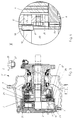
- Figure 1 shows a wheel head 1 of a drive axle, not shown, which essentially contains the following components: a planet carrier 2, a planetary gear 3, designed as a disk pack, in this example running in oil, disk brake 4, a support disk 5, a disk pack 4 and support disk 5 spanning ring gear carrier 6, a locking screw 7 inserted in the face of the planet carrier 2, and an as Screw 8 acting against rotation in the area of the support disk 5.
- the multi-disk brake 4 is axially actuated by a piston 10 that can be pressurized with pressure medium against the support disk, which is secured against rotation in the operating state, and thus stationary 5 delivered.
- the multi-disk brake 4 is adjustable, which is described in more detail below:
- the multi-disc brake 4 is adjusted, for example, when the vehicle is jacked up, so that the wheels (not shown) on which the brake 4 is to be adjusted can be freely rotated.
- a multi-disc brake 4 running in oil is described in this example, so that before the actual adjustment process, for example by removing the screw plug 7 (or any oil drain screw in the area of the wheel head 1), the oil is drained from the wheel head 1.
- the planet carrier 2 is then rotated in the circumferential direction until the locking screw 8 is visible in the opening 11 of the locking screw 7. Using a suitable tool, the locking screw 8 is removed through the opening 11, so that the anti-rotation device between the support disk 5 and the ring gear carrier 6 is now neutralized.
- the support disk 5 and the ring gear carrier 6 are provided with corresponding threads (see FIG. 2). Following this, the screw plug 7 is reinserted into the opening 11, a metal rod 12 being guided through a through hole 13 provided in the screw plug 7 and in a form-fitting manner with the support disk 5 is connected. This can be achieved, for example, through a narrow bore or a screw connection. Now the planet carrier 2 is rotated in the circumferential direction until the support disk 5, which is connected to the ring gear carrier 6 via the thread mentioned above, strikes the disk pack 4 while overcoming the axial play present in the same. The planet carrier 2 is then rotated back by a certain number of revolutions or a predetermined angle of rotation. The number of turns multiplied by the pitch of the thread corresponds to the desired clearance. After completion of this adjustment process, the screw plug 7 is removed from the wheel head 1 in connection with the metal rod 12. The locking screw 8 is reinserted with the already mentioned tool into the associated bore and then the planet carrier 2 is closed and the wheel head 1 is filled with oil again.
- FIG. 2 shows an enlarged view of area X, i.e. the area of the anti-rotation device.
- the following components can be seen: the support disk 5, the disk pack 4, the metal rod 12 which is guided in a bore 14 in the end face 15 of the support disk 5.
- the metal rod 12 is equipped with a stop 16 which comes to rest on the end face 15.
- the locking screw 8, which in this example interacts with a disk element 17, can also be seen.
- the locking screw 8 is inserted at a predetermined angle of inclination into an associated bore 19 made in the offset end face region 18 of the support disc 5, the disc element 17 engaging on the one hand on the offset region 18 of the support disc 5 and on the other hand in a groove 20 of the ring gear carrier 6.
- the external thread 21 of the support disk 5 and the internal thread 22 of the ring gear carrier 6 can now also be seen.
- Figure 3 shows an alternative wheel head 1 ', the same components are also provided with the same reference numerals. Differences between Figures 1 and 3 are essentially in the area of the support plate and the anti-rotation between the same and the ring gear carrier 6.
- the anti-rotation device is effected in this example by a locking screw 23 running parallel to the shaft 9.
- the support disc is in this example formed from two radially nested annular components 5 ', 5'', these components 5' and 5 '' being provided with corresponding threads (not shown).
- a locking ring 24 provided axially outside of the component 5 'prevents an unwanted axial displacement of the components 5', 5 '' when the brake is actuated.
- the outer ring 5 ′′ is guided against rotation with respect to the ring gear carrier 6, which in this example has no thread, by a grub screw 25, while the locking ring 24 is provided against rotation with the ring gear carrier by means of metal pins 26.
- the positive connection between the planet carrier 2 and the support disk is produced essentially analogously to FIG. 1, namely by the locking screw 7 in connection with the metal rod 12, which in this example is on the inner ring 5 'which is movable relative to the outer ring 5'' Facility is coming.
- the planet carrier 2 is rotated.
- the inner ring 5 ' moves in the direction of the disk pack 4.
- the planet carrier 2 is rotated back by the number of revolutions indicated or the predetermined angle of rotation.
- the number of revolutions multiplied by the pitch of the thread between the inner 5 'and outer ring 5'' gives the clearance to be set.
- the locking screw 7 and the metal rod 12 are removed from the wheel head 1 'and the locking screw 23 is reinserted to the intended location using a suitable tool. Then the wheel head 1 'is closed and refilled with oil.
- Views X and Z are shown enlarged, view Z showing the grub screw 25 between the outer ring 5 ′′ of the support disk and the ring gear carrier 6.
- the following components can be seen in view X according to FIG. 4: the inner ring 5 'of the support disk, the ring gear carrier 6, the disk set 4, the metal rod 12 which is guided in a bore 14 of the inner ring 5' and is provided with a stop 16 .
- the locking screw 23 and the metal pin 26 for fixing the locking ring 24 relative to the ring gear carrier 6 can also be seen, the locking screw 23 engages in a recess 27 of the locking ring 24 and can be connected to the inner ring 5 'of the support disk.
- FIG. 5 shows a further wheel head 1 ′′, which is constructed essentially analogously to FIG. 3, so that the same components are provided with the same reference numerals, the support disk 5 again being formed in one piece analogously to FIG. 1 and with an external thread (see FIG. 6). is provided. Differences from FIG. 3 can essentially be seen in the structural design of the anti-rotation device. Until the positive connection of parts 2 and 5 is established, the process steps are to be carried out analogously to those already set out.
- the support disk 5 is held axially analogous to FIG. 3 by a locking ring 24, which is arranged against rotation with the ring gear carrier 6 by means of metal pins 26.
- the planet carrier 2 is rotated until the support plate 5 overcomes the disk set 4 while overcoming it Axial play touched.
- the support disc 5 is connected to the ring gear carrier 6 via the thread already mentioned.
- the planet carrier 2 is rotated back by a certain number of revolutions or over a predetermined angle of rotation. The number of revolutions multiplied by the pitch of the thread between the support disk 5 and the ring gear carrier 6 corresponds to the clearance to be set.
- the locking screw 7 and the metal rod 12 are then removed from the wheel head 1 ′′. Then the locking screw 28 is reinserted into the support disk 5, with the appropriate tool already mentioned.
- the planet carrier 2 is then closed and the wheel head 1 ′′ is filled with oil again.
- FIG. 6 shows an enlargement of the anti-rotation area designated by X.
- the following components can be seen: the support disc 5, the ring gear carrier 6, the disk set 4, the metal rod 12 which is introduced into a bore 14 in the end face 15 of the support disc 5 and is provided with a stop 16.
- the locking screw 28 is provided in a recess 27 of the locking ring 24 and is screwed to the support plate 5.
Landscapes
- Engineering & Computer Science (AREA)
- General Engineering & Computer Science (AREA)
- Mechanical Engineering (AREA)
- Braking Arrangements (AREA)
Applications Claiming Priority (2)
| Application Number | Priority Date | Filing Date | Title |
|---|---|---|---|
| DE19500765A DE19500765A1 (de) | 1995-01-13 | 1995-01-13 | Verfahren und Einrichtung zur Nachstellung einer, insbesondere in Öl laufenden, Lamellenbremse |
| DE19500765 | 1995-01-13 |
Publications (3)
| Publication Number | Publication Date |
|---|---|
| EP0722051A2 true EP0722051A2 (fr) | 1996-07-17 |
| EP0722051A3 EP0722051A3 (fr) | 1997-10-01 |
| EP0722051B1 EP0722051B1 (fr) | 1999-08-04 |
Family
ID=7751369
Family Applications (1)
| Application Number | Title | Priority Date | Filing Date |
|---|---|---|---|
| EP95118936A Expired - Lifetime EP0722051B1 (fr) | 1995-01-13 | 1995-12-01 | Procédé et dispositif d'ajustage pour un frein multidisques en particulier à huile |
Country Status (4)
| Country | Link |
|---|---|
| EP (1) | EP0722051B1 (fr) |
| AT (1) | ATE182966T1 (fr) |
| DE (2) | DE19500765A1 (fr) |
| ES (1) | ES2139823T3 (fr) |
Cited By (6)
| Publication number | Priority date | Publication date | Assignee | Title |
|---|---|---|---|---|
| WO1998050714A3 (fr) * | 1997-05-02 | 1999-04-15 | Zahnradfabrik Friedrichshafen | Transmission a frein integre |
| EP1122162A3 (fr) * | 2000-02-07 | 2002-01-30 | Shimano Inc. | Frein à disque pour vélo |
| US6869380B2 (en) | 2003-06-11 | 2005-03-22 | Zf Friedrichshafen Ag | Driveline for mobile-vehicles |
| US6890282B2 (en) | 2003-06-11 | 2005-05-10 | Zf Friedrichshafen Ag | Driveline for mobile vehicles |
| CN101386329B (zh) * | 2007-09-13 | 2011-03-23 | 力帆实业(集团)股份有限公司 | 一种摩托车液压盘式后制动装置 |
| US11149786B2 (en) | 2020-02-28 | 2021-10-19 | Pratt & Whitney Canada Corp. | Carrier journal with anti-rotation feature |
Families Citing this family (2)
| Publication number | Priority date | Publication date | Assignee | Title |
|---|---|---|---|---|
| SE509788C2 (sv) | 1997-07-18 | 1999-03-08 | Volvo Constr Equip Components | Planetväxel för ett fordonshjul |
| DE10325781B4 (de) * | 2003-06-05 | 2012-12-13 | Sew-Eurodrive Gmbh & Co. Kg | Umlaufgetriebe |
Citations (3)
| Publication number | Priority date | Publication date | Assignee | Title |
|---|---|---|---|---|
| GB2024345A (en) | 1979-06-07 | 1980-01-09 | Gen Motors Corp | Disc brake |
| DE3932719A1 (de) | 1988-10-07 | 1990-04-12 | Zahnradfabrik Friedrichshafen | Reibscheiben-nachstellvorrichtung |
| DE4338468A1 (de) | 1992-11-26 | 1994-06-01 | Orenstein & Koppel Ag | Verfahren und Einrichtung zur Verschleißmessung an Lamellenbremsen |
Family Cites Families (3)
| Publication number | Priority date | Publication date | Assignee | Title |
|---|---|---|---|---|
| GB729060A (en) * | 1952-10-08 | 1955-05-04 | Leonard Taylor | Improvements in or relating to friction clutches or brakes |
| US2920722A (en) * | 1958-02-12 | 1960-01-12 | Gen Motors Corp | Brake-adjusting device |
| GB1068637A (en) * | 1963-09-11 | 1967-05-10 | Zahnradfabrik Friedrichshafen | Improvements in or relating to electromagnetically actuated friction clutches or brakes |
-
1995
- 1995-01-13 DE DE19500765A patent/DE19500765A1/de not_active Withdrawn
- 1995-12-01 DE DE59506529T patent/DE59506529D1/de not_active Expired - Fee Related
- 1995-12-01 AT AT95118936T patent/ATE182966T1/de not_active IP Right Cessation
- 1995-12-01 ES ES95118936T patent/ES2139823T3/es not_active Expired - Lifetime
- 1995-12-01 EP EP95118936A patent/EP0722051B1/fr not_active Expired - Lifetime
Patent Citations (3)
| Publication number | Priority date | Publication date | Assignee | Title |
|---|---|---|---|---|
| GB2024345A (en) | 1979-06-07 | 1980-01-09 | Gen Motors Corp | Disc brake |
| DE3932719A1 (de) | 1988-10-07 | 1990-04-12 | Zahnradfabrik Friedrichshafen | Reibscheiben-nachstellvorrichtung |
| DE4338468A1 (de) | 1992-11-26 | 1994-06-01 | Orenstein & Koppel Ag | Verfahren und Einrichtung zur Verschleißmessung an Lamellenbremsen |
Cited By (7)
| Publication number | Priority date | Publication date | Assignee | Title |
|---|---|---|---|---|
| WO1998050714A3 (fr) * | 1997-05-02 | 1999-04-15 | Zahnradfabrik Friedrichshafen | Transmission a frein integre |
| US6817963B1 (en) | 1997-05-02 | 2004-11-16 | Zf Friedrichshafen Ag | Automotive gearbox with an integrated brake |
| EP1122162A3 (fr) * | 2000-02-07 | 2002-01-30 | Shimano Inc. | Frein à disque pour vélo |
| US6869380B2 (en) | 2003-06-11 | 2005-03-22 | Zf Friedrichshafen Ag | Driveline for mobile-vehicles |
| US6890282B2 (en) | 2003-06-11 | 2005-05-10 | Zf Friedrichshafen Ag | Driveline for mobile vehicles |
| CN101386329B (zh) * | 2007-09-13 | 2011-03-23 | 力帆实业(集团)股份有限公司 | 一种摩托车液压盘式后制动装置 |
| US11149786B2 (en) | 2020-02-28 | 2021-10-19 | Pratt & Whitney Canada Corp. | Carrier journal with anti-rotation feature |
Also Published As
| Publication number | Publication date |
|---|---|
| DE19500765A1 (de) | 1996-07-25 |
| EP0722051A3 (fr) | 1997-10-01 |
| ATE182966T1 (de) | 1999-08-15 |
| ES2139823T3 (es) | 2000-02-16 |
| EP0722051B1 (fr) | 1999-08-04 |
| DE59506529D1 (de) | 1999-09-09 |
Similar Documents
| Publication | Publication Date | Title |
|---|---|---|
| DE2619011C3 (de) | Planetenwechselgetriebe für Fahrzeuge | |
| DE3900075C2 (fr) | ||
| DE3143607C2 (fr) | ||
| EP3027928B1 (fr) | Frein à disque pour un véhicule automobile pourvu d'un dispositif d'étanchéité conçu pour frein de stationnement électronique | |
| DE2420985C2 (de) | Scheibenbremse, insbesondere für Kraftfahrzeuge | |
| EP0418507B1 (fr) | Dispositif de freinage et/ou de serrage | |
| DE3149880C2 (de) | Druckmittelbetätigte Lamellenkupplung | |
| DE2621851A1 (de) | Dehnbare, stroemungsmittelbetaetigte einrichtung fuer flugzeugmehrscheibenbremsen | |
| EP0271864A2 (fr) | Mécanisme d'actionnement à réajustage automatique pour freins, en particulier pour véhicules poids lourd | |
| DE2840300A1 (de) | Reibungsbremse und verfahren zu ihrem einbau | |
| DE3508039C2 (de) | Innen umgriffene Scheibenbremse, insbesondere für Kraftfahrzeuge | |
| DE4023636A1 (de) | Armatur zum absperren einer stroemung | |
| EP0436906B1 (fr) | Dispositif d'actionnement pour frein de véhicule, notamment frein à disque | |
| EP0722051B1 (fr) | Procédé et dispositif d'ajustage pour un frein multidisques en particulier à huile | |
| DE3336119C2 (fr) | ||
| EP0705419B1 (fr) | Procede et dispositif permettant de mesurer l'usure de freins multidisques | |
| DE102017207674A1 (de) | Arretierstift mit Fuss für Haltefeder in Scheibenbremsenpaket Reaktionsplatte bei der Montage und zum Betrieb einer Statorscheibe | |
| DE3640659A1 (de) | Selbstnachstellender rad(brems)zylinder fuer trommelbremse | |
| DE1550680B2 (de) | Ausgleichsgetriebe mit Konuskupplungen | |
| EP2106509A1 (fr) | Frein à disque pour un véhicule automobile et son boîtier | |
| DE2547083A1 (de) | Scheibenbremse | |
| DE69100727T2 (de) | Fahrzeugbremsen. | |
| DE69902374T2 (de) | Werkzeugwechselgerät | |
| DE29500478U1 (de) | Einrichtung zur Nachstellung einer, insbesondere in Öl laufenden, Lamellenbremse | |
| DE4226143A1 (de) | Druckgesteuerte axial verschiebbare Nachstellvorrichtung |
Legal Events
| Date | Code | Title | Description |
|---|---|---|---|
| PUAI | Public reference made under article 153(3) epc to a published international application that has entered the european phase |
Free format text: ORIGINAL CODE: 0009012 |
|
| AK | Designated contracting states |
Kind code of ref document: A2 Designated state(s): AT BE CH DE DK ES FR GB GR IE IT LI LU MC NL PT SE |
|
| PUAL | Search report despatched |
Free format text: ORIGINAL CODE: 0009013 |
|
| AK | Designated contracting states |
Kind code of ref document: A3 Designated state(s): AT BE CH DE DK ES FR GB GR IE IT LI LU MC NL PT SE |
|
| 17P | Request for examination filed |
Effective date: 19970905 |
|
| 17Q | First examination report despatched |
Effective date: 19980129 |
|
| GRAG | Despatch of communication of intention to grant |
Free format text: ORIGINAL CODE: EPIDOS AGRA |
|
| GRAG | Despatch of communication of intention to grant |
Free format text: ORIGINAL CODE: EPIDOS AGRA |
|
| GRAH | Despatch of communication of intention to grant a patent |
Free format text: ORIGINAL CODE: EPIDOS IGRA |
|
| GRAH | Despatch of communication of intention to grant a patent |
Free format text: ORIGINAL CODE: EPIDOS IGRA |
|
| GRAA | (expected) grant |
Free format text: ORIGINAL CODE: 0009210 |
|
| AK | Designated contracting states |
Kind code of ref document: B1 Designated state(s): AT BE CH DE DK ES FR GB GR IE IT LI LU MC NL PT SE |
|
| PG25 | Lapsed in a contracting state [announced via postgrant information from national office to epo] |
Ref country code: NL Free format text: LAPSE BECAUSE OF FAILURE TO SUBMIT A TRANSLATION OF THE DESCRIPTION OR TO PAY THE FEE WITHIN THE PRESCRIBED TIME-LIMIT Effective date: 19990804 Ref country code: GR Free format text: LAPSE BECAUSE OF NON-PAYMENT OF DUE FEES Effective date: 19990804 |
|
| REF | Corresponds to: |
Ref document number: 182966 Country of ref document: AT Date of ref document: 19990815 Kind code of ref document: T |
|
| REG | Reference to a national code |
Ref country code: CH Ref legal event code: EP |
|
| ITF | It: translation for a ep patent filed | ||
| REF | Corresponds to: |
Ref document number: 59506529 Country of ref document: DE Date of ref document: 19990909 |
|
| REG | Reference to a national code |
Ref country code: IE Ref legal event code: FG4D Free format text: GERMAN |
|
| PG25 | Lapsed in a contracting state [announced via postgrant information from national office to epo] |
Ref country code: PT Free format text: LAPSE BECAUSE OF FAILURE TO SUBMIT A TRANSLATION OF THE DESCRIPTION OR TO PAY THE FEE WITHIN THE PRESCRIBED TIME-LIMIT Effective date: 19991104 Ref country code: DK Free format text: LAPSE BECAUSE OF FAILURE TO SUBMIT A TRANSLATION OF THE DESCRIPTION OR TO PAY THE FEE WITHIN THE PRESCRIBED TIME-LIMIT Effective date: 19991104 |
|
| ET | Fr: translation filed | ||
| GBT | Gb: translation of ep patent filed (gb section 77(6)(a)/1977) |
Effective date: 19991101 |
|
| PG25 | Lapsed in a contracting state [announced via postgrant information from national office to epo] |
Ref country code: LU Free format text: LAPSE BECAUSE OF NON-PAYMENT OF DUE FEES Effective date: 19991201 Ref country code: AT Free format text: LAPSE BECAUSE OF NON-PAYMENT OF DUE FEES Effective date: 19991201 |
|
| PG25 | Lapsed in a contracting state [announced via postgrant information from national office to epo] |
Ref country code: LI Free format text: LAPSE BECAUSE OF NON-PAYMENT OF DUE FEES Effective date: 19991231 Ref country code: CH Free format text: LAPSE BECAUSE OF NON-PAYMENT OF DUE FEES Effective date: 19991231 Ref country code: BE Free format text: LAPSE BECAUSE OF NON-PAYMENT OF DUE FEES Effective date: 19991231 |
|
| NLV1 | Nl: lapsed or annulled due to failure to fulfill the requirements of art. 29p and 29m of the patents act | ||
| REG | Reference to a national code |
Ref country code: ES Ref legal event code: FG2A Ref document number: 2139823 Country of ref document: ES Kind code of ref document: T3 |
|
| REG | Reference to a national code |
Ref country code: GB Ref legal event code: 732E |
|
| PLBE | No opposition filed within time limit |
Free format text: ORIGINAL CODE: 0009261 |
|
| STAA | Information on the status of an ep patent application or granted ep patent |
Free format text: STATUS: NO OPPOSITION FILED WITHIN TIME LIMIT |
|
| BERE | Be: lapsed |
Owner name: ORENSTEIN & KOPPEL A.G. O&K Effective date: 19991231 |
|
| PG25 | Lapsed in a contracting state [announced via postgrant information from national office to epo] |
Ref country code: MC Free format text: LAPSE BECAUSE OF NON-PAYMENT OF DUE FEES Effective date: 20000630 |
|
| 26N | No opposition filed | ||
| REG | Reference to a national code |
Ref country code: IE Ref legal event code: FD4D |
|
| REG | Reference to a national code |
Ref country code: ES Ref legal event code: PC2A |
|
| REG | Reference to a national code |
Ref country code: FR Ref legal event code: TP |
|
| REG | Reference to a national code |
Ref country code: GB Ref legal event code: IF02 |
|
| REG | Reference to a national code |
Ref country code: GB Ref legal event code: 732E |
|
| REG | Reference to a national code |
Ref country code: ES Ref legal event code: PC2A |
|
| REG | Reference to a national code |
Ref country code: FR Ref legal event code: TP Ref country code: FR Ref legal event code: CD |
|
| PG25 | Lapsed in a contracting state [announced via postgrant information from national office to epo] |
Ref country code: IT Free format text: LAPSE BECAUSE OF NON-PAYMENT OF DUE FEES;WARNING: LAPSES OF ITALIAN PATENTS WITH EFFECTIVE DATE BEFORE 2007 MAY HAVE OCCURRED AT ANY TIME BEFORE 2007. THE CORRECT EFFECTIVE DATE MAY BE DIFFERENT FROM THE ONE RECORDED. Effective date: 20051201 |
|
| PGFP | Annual fee paid to national office [announced via postgrant information from national office to epo] |
Ref country code: DE Payment date: 20051212 Year of fee payment: 11 |
|
| PGFP | Annual fee paid to national office [announced via postgrant information from national office to epo] |
Ref country code: SE Payment date: 20051214 Year of fee payment: 11 |
|
| PGFP | Annual fee paid to national office [announced via postgrant information from national office to epo] |
Ref country code: ES Payment date: 20051215 Year of fee payment: 11 |
|
| PGFP | Annual fee paid to national office [announced via postgrant information from national office to epo] |
Ref country code: FR Payment date: 20051219 Year of fee payment: 11 |
|
| PGFP | Annual fee paid to national office [announced via postgrant information from national office to epo] |
Ref country code: GB Payment date: 20051222 Year of fee payment: 11 |
|
| PG25 | Lapsed in a contracting state [announced via postgrant information from national office to epo] |
Ref country code: SE Free format text: LAPSE BECAUSE OF NON-PAYMENT OF DUE FEES Effective date: 20061202 |
|
| PG25 | Lapsed in a contracting state [announced via postgrant information from national office to epo] |
Ref country code: DE Free format text: LAPSE BECAUSE OF NON-PAYMENT OF DUE FEES Effective date: 20070703 |
|
| EUG | Se: european patent has lapsed | ||
| GBPC | Gb: european patent ceased through non-payment of renewal fee |
Effective date: 20061201 |
|
| REG | Reference to a national code |
Ref country code: FR Ref legal event code: ST Effective date: 20070831 |
|
| PG25 | Lapsed in a contracting state [announced via postgrant information from national office to epo] |
Ref country code: GB Free format text: LAPSE BECAUSE OF NON-PAYMENT OF DUE FEES Effective date: 20061201 |
|
| REG | Reference to a national code |
Ref country code: ES Ref legal event code: FD2A Effective date: 20061202 |
|
| PG25 | Lapsed in a contracting state [announced via postgrant information from national office to epo] |
Ref country code: FR Free format text: LAPSE BECAUSE OF NON-PAYMENT OF DUE FEES Effective date: 20070102 Ref country code: ES Free format text: LAPSE BECAUSE OF NON-PAYMENT OF DUE FEES Effective date: 20061202 |
|
| PGRI | Patent reinstated in contracting state [announced from national office to epo] |
Ref country code: IT Effective date: 20090401 |
|
| PGFP | Annual fee paid to national office [announced via postgrant information from national office to epo] |
Ref country code: IT Payment date: 20061231 Year of fee payment: 12 |
|
| PGRI | Patent reinstated in contracting state [announced from national office to epo] |
Ref country code: IT Effective date: 20090401 |