EP0722206A2 - Austauschbare Schlüsselelemente für Leiterplattenrandverbinder - Google Patents
Austauschbare Schlüsselelemente für Leiterplattenrandverbinder Download PDFInfo
- Publication number
- EP0722206A2 EP0722206A2 EP95120080A EP95120080A EP0722206A2 EP 0722206 A2 EP0722206 A2 EP 0722206A2 EP 95120080 A EP95120080 A EP 95120080A EP 95120080 A EP95120080 A EP 95120080A EP 0722206 A2 EP0722206 A2 EP 0722206A2
- Authority
- EP
- European Patent Office
- Prior art keywords
- key
- slot
- card
- opening
- continuity
- Prior art date
- Legal status (The legal status is an assumption and is not a legal conclusion. Google has not performed a legal analysis and makes no representation as to the accuracy of the status listed.)
- Withdrawn
Links
- 230000037431 insertion Effects 0.000 claims abstract description 18
- 238000003780 insertion Methods 0.000 claims abstract description 18
- 239000004020 conductor Substances 0.000 claims abstract description 14
- 239000000463 material Substances 0.000 claims description 5
- 230000002265 prevention Effects 0.000 claims 1
- 230000000694 effects Effects 0.000 description 3
- 230000000712 assembly Effects 0.000 description 2
- 238000000429 assembly Methods 0.000 description 2
- 230000009286 beneficial effect Effects 0.000 description 1
- 238000010276 construction Methods 0.000 description 1
- 239000011810 insulating material Substances 0.000 description 1
- 230000013011 mating Effects 0.000 description 1
- 230000000717 retained effect Effects 0.000 description 1
Images

Classifications
-
- H—ELECTRICITY
- H01—ELECTRIC ELEMENTS
- H01R—ELECTRICALLY-CONDUCTIVE CONNECTIONS; STRUCTURAL ASSOCIATIONS OF A PLURALITY OF MUTUALLY-INSULATED ELECTRICAL CONNECTING ELEMENTS; COUPLING DEVICES; CURRENT COLLECTORS
- H01R12/00—Structural associations of a plurality of mutually-insulated electrical connecting elements, specially adapted for printed circuits, e.g. printed circuit boards [PCB], flat or ribbon cables, or like generally planar structures, e.g. terminal strips, terminal blocks; Coupling devices specially adapted for printed circuits, flat or ribbon cables, or like generally planar structures; Terminals specially adapted for contact with, or insertion into, printed circuits, flat or ribbon cables, or like generally planar structures
- H01R12/70—Coupling devices
- H01R12/7005—Guiding, mounting, polarizing or locking means; Extractors
-
- H—ELECTRICITY
- H10—SEMICONDUCTOR DEVICES; ELECTRIC SOLID-STATE DEVICES NOT OTHERWISE PROVIDED FOR
- H10H—INORGANIC LIGHT-EMITTING SEMICONDUCTOR DEVICES HAVING POTENTIAL BARRIERS
- H10H20/00—Individual inorganic light-emitting semiconductor devices having potential barriers, e.g. light-emitting diodes [LED]
- H10H20/80—Constructional details
- H10H20/85—Packages
- H10H20/8506—Containers
-
- H—ELECTRICITY
- H01—ELECTRIC ELEMENTS
- H01R—ELECTRICALLY-CONDUCTIVE CONNECTIONS; STRUCTURAL ASSOCIATIONS OF A PLURALITY OF MUTUALLY-INSULATED ELECTRICAL CONNECTING ELEMENTS; COUPLING DEVICES; CURRENT COLLECTORS
- H01R12/00—Structural associations of a plurality of mutually-insulated electrical connecting elements, specially adapted for printed circuits, e.g. printed circuit boards [PCB], flat or ribbon cables, or like generally planar structures, e.g. terminal strips, terminal blocks; Coupling devices specially adapted for printed circuits, flat or ribbon cables, or like generally planar structures; Terminals specially adapted for contact with, or insertion into, printed circuits, flat or ribbon cables, or like generally planar structures
- H01R12/70—Coupling devices
- H01R12/71—Coupling devices for rigid printing circuits or like structures
- H01R12/72—Coupling devices for rigid printing circuits or like structures coupling with the edge of the rigid printed circuits or like structures
- H01R12/721—Coupling devices for rigid printing circuits or like structures coupling with the edge of the rigid printed circuits or like structures cooperating directly with the edge of the rigid printed circuits
-
- H—ELECTRICITY
- H01—ELECTRIC ELEMENTS
- H01R—ELECTRICALLY-CONDUCTIVE CONNECTIONS; STRUCTURAL ASSOCIATIONS OF A PLURALITY OF MUTUALLY-INSULATED ELECTRICAL CONNECTING ELEMENTS; COUPLING DEVICES; CURRENT COLLECTORS
- H01R13/00—Details of coupling devices of the kinds covered by groups H01R12/70 or H01R24/00 - H01R33/00
- H01R13/64—Means for preventing incorrect coupling
- H01R13/645—Means for preventing incorrect coupling by exchangeable elements on case or base
-
- H—ELECTRICITY
- H01—ELECTRIC ELEMENTS
- H01S—DEVICES USING THE PROCESS OF LIGHT AMPLIFICATION BY STIMULATED EMISSION OF RADIATION [LASER] TO AMPLIFY OR GENERATE LIGHT; DEVICES USING STIMULATED EMISSION OF ELECTROMAGNETIC RADIATION IN WAVE RANGES OTHER THAN OPTICAL
- H01S5/00—Semiconductor lasers
- H01S5/02—Structural details or components not essential to laser action
- H01S5/022—Mountings; Housings
- H01S5/02235—Getter material for absorbing contamination
-
- H—ELECTRICITY
- H01—ELECTRIC ELEMENTS
- H01S—DEVICES USING THE PROCESS OF LIGHT AMPLIFICATION BY STIMULATED EMISSION OF RADIATION [LASER] TO AMPLIFY OR GENERATE LIGHT; DEVICES USING STIMULATED EMISSION OF ELECTROMAGNETIC RADIATION IN WAVE RANGES OTHER THAN OPTICAL
- H01S5/00—Semiconductor lasers
- H01S5/02—Structural details or components not essential to laser action
- H01S5/022—Mountings; Housings
- H01S5/0225—Out-coupling of light
- H01S5/02251—Out-coupling of light using optical fibres
Definitions
- the invention relates to interconnection systems for electronic apparatus and in particular to a keyed card edge connecting system wherein a card edge connector is adapted with interchangeable keying to uniquely accommodate a large number of specific cards.
- a type of interconnecting system heavily used in the art involves the mounting of components such as integrated circuits on insulating printed Wiring bearing members having the wiring conductors extending to an edge of the insulating member to serve as contacts to external wiring.
- the printed wiring bearing members come in various sizes and are generally referred to as cards.
- the edge of the card with the wiring conductor contacts is positioned in a slot in a supporting connector member with mating external wiring contacts in the slot.
- the slot in the supporting conductor member has a width and depth relationship to the card to provide support for the card and retains the assembly in electrical contact.
- the invention is a system of keying the insertion of a conductor bearing card edge into a slotted supporting connector to accommodate a large number of different cards through the providing of a rotatable key opening in the slot face of the slotted supporting connector together with the providing of a specific card feature accommodating key, positioned in the opening.
- the key and opening are arranged so that the key can be in one of several positions controlled by the correspondence of the shape of the opening with the shape of the key, and with the shape of the key in turn providing an interruption to the continuity of the slot at different lengths along the slot.
- Cards are provided with at least one edge notch, so positioned in the card insertion edge to be at the slot interruption location for the particular position of the key.
- a large number of slot lengths are achievable with a single key part.
- the key and opening combinations are such that, in the preferred embodiment, the key when in position in the opening does not extend above the slot surface of the slotted supporting connector so as to minimize strength reduction and loss of card area both of which in turn enhances the downsizing
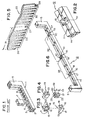
- Figure 1 is a perspective view of a prior art slotted supporting connector and key combination.
- Figure 2 is a perspective view which shows the opening for the invention in a portion of a slotted supporting connector.
- Figure 3 is a perspective view of two positions of an embossed feature rotatable key of the invention.
- Figure 4 is a perspective view of two positions of a slot feature cubic rotatable key of the invention.
- Figure 5 is a perspective view of a card illustrating the use of notches for unique slot lengths.
- Figure 6 is a perspective view of a slotted supporting connector illustrating the use of several, embossed feature rotatable keys, in position,in accordance with the invention.
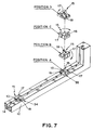
- Figure 7 is a perspective view showing the effect on slot length of the embossed feature type key rotation.
- Figure 8 is a vertical exploded view of the possible positions in the slotted feature cubic type key rotation.
- Figure 9 is a perspective view of a connecting system assembly of six slotted supporting connector members each with three spaced openings and with a slotted feature cubic key in each of the six positions.
- the component bearing cards are supported by having their edges with the external contact conductors inserted into the slot of a slotted supporting connector member.
- a key member shaped to fit into an opening in the slot face of the slotted supporting connector is used to insure that an incorrect card cannot be inserted into an incompatible circuitry configuration.
- FIG 1 there is shown a perspective view of a typical prior art slotted supporting connector and key structure.
- the slotted supporting connector member 1 has a card edge receiving slot 2 running longitudinally in a slot face 3 of the connector 1.
- the connector member 1 also has a plurality of external wiring connecting conductive members 4 that contact the external contact conductors on the edge of the card, not shown, that is inserted into the slot 2.
- the slotted supporting connector member 1 in some constructions has a right angle tower portion 5 and the conductive members 4 are extended, not shown, onto the tower portion 5. The friction contact between the members 4 and the conductors at the card edge over the area in the slot 2 provides sufficient and reliable support for the card.
- FIG. 1 an example opening 6 is provided into which, in an exploded view, a key 7 is insertable. External wiring is attached to the connecting conductive members 4, out of view in this figure.
- the slotted supporting connectors 1 are usually retained in a frame with dowels on the underside out of view in this figure.
- the slotted supporting connector is of insulating material such as a moldable plastic with the plurality of connecting conductive members 4 and with the opening 6 molded into it.
- the key is also of moldable plastic.
- Figure 1 The structure of Figure 1 is available in the art with the opening 6 and the key 7 specifiable, an example being the "SIMM socket" produced by the AMP Corporation in Harrisburgh, Pa. There is however, a need for much greater card variation capability, while retaining the externally wired slotted supporting connector assemblies, than the prior art structure of Figure 1 will accommodate.
- FIG. 2 there is shown a perspective view of a square example of the rotatable key opening 10 in the slot face 11 of the slotted supporting connector 12.
- the opening 10 has a depth dimension 13 to accommodate the key and selected to position the uppermost portion of the key at the level of the slot face 11 of the slotted supporting connector 12.
- the slot itself is labelled element 14.
- the key pieces are illustrated in two rotated views each, in Figures 3 and 4.
- the insertion edge of the card is interrupted at different lengths by embossed features or slot features of the key
- the embossed feature key 15 has a plane portion 16 with the dimensions of the opening 10 in Fig.2, a first embossed feature portion 17 along one edge of the portion 16 and with a second embossed portion 18 perpendicular to the first embossed portion 17 and sufficiently off the center of the portion 17 so as not to be in the slot 14 of Figure 2 when the key 15 is positioned in the opening 10 of Figure 2 with the portion 17 transverse of the slot 14.
- the height of the key 15 is essentially the same as the dimension 13 of Figure 2.
- the slotted feature key 19 is a cube having equal side and depth 13 dimensions, to be compatible with the opening 10 with essentially the same dimensions.
- the slotted feature key 19 has a different, card edge accommodating slot 20, 21, 22 and 23 in each side face, that extends into one end face, and two of which, 22 and 23 are intersecting.
- the material of the key 19 remaining between the slots at the end surface serve as slot interruptors in use.
- the slots stop before reaching the remaining face, leaving material to serve as a slot interruption when the key is on it's side.
- FIG. 5 The interrelationship of the card, the key piece or pieces and the slotted supporting connector is shown in connection with Figures 5 and 6.
- Figures 5 and 6 wherein perspective views are shown like reference numerals for like elements are used where appropriate.
- a portion of a card is shown that has notches that separate insertion edge length portions.
- a multi key slotted supporting connector is shown with the rotational position of the keys defining corresponding slot lengths.
- the example portion of a card 25 has example notches 26, 27 and 28 to define unique and different slot lengths 29 and 30.
- the notches need only be to the insertion depth of the card edge when it is inserted into the slot and need only be to the width of the slot interrupting portions of the key.
- the slotted supporting connector member 12 is provided with, as an example three key openings 10, each with a key 15 positioned therein in a different rotational position.
- the different rotational positions place, using the key of Figure 3 as an illustration the portions 17 and 18 transverse of the slot 14, which produces the different slot distances 32 and 33 required for the card edge lengths 29 and 30 respectively between notches 26 and 27, and, 27 and 28 respectively of the example card portion 25 in Figure 5.
- FIG. 7 a perspective view is shown of the effect on slot lengths of the rotational positioning of the key type of Figure 3.
- a portion of a slotted supporting connector 12 is shown, with two openings 10, and with two keys of the type of Figure 4, labelled elements 34 and 35, in each opening.
- the four rotational positions A,B,C and D, available to each key, are shown for visibility, in a single superimposed exploded view above element 35.
- different portions 17 and 18 of each key serve as the transverse boundaries of the available slot length for card edge insertion.
- the element 35 key is in position A and the element 34 key is in position D.
- the longest slot length would occur with element 35 in position A and with element 34 in position C whereas the shortest slot length would be with element 35 in position C and with element 34 in position A, and intermediate lengths can be achieved using other combinations of positions.
- FIG. 8 a vertical exploded view is provided, showing the 6 rotational positions.
- Figure 9 a perspective view of a connecting system is shown having six parallel connecting elements 12, each with three openings 10, and with a key 19 in each of the 6 rotational positions.
- the key places a portion of the key piece transverse of the slot to interrupt the continuity and thereby prevent entry of a card edge that is beyond the correct length.
- the shortest slot length between two adjacent openings would be to position key 36 in position 5 and key 37 in position 6; whereas the longest slot length would be to have the key 36 be in position 6 and the key 37 be in position 5.
- the system provides a rotatable key opening in the slot face of the slotted supporting connector and provides a specific card feature accommodating key piece that is positioned in the rotatable key opening.
- the key and opening are arranged so that the shape of the key provides an interruption to the continuity of the slot at a specific distances along the slot length corresponding to a specific card edge.
Landscapes
- Coupling Device And Connection With Printed Circuit (AREA)
- Details Of Connecting Devices For Male And Female Coupling (AREA)
Applications Claiming Priority (2)
| Application Number | Priority Date | Filing Date | Title |
|---|---|---|---|
| US37163195A | 1995-01-12 | 1995-01-12 | |
| US371631 | 1999-08-11 |
Publications (1)
| Publication Number | Publication Date |
|---|---|
| EP0722206A2 true EP0722206A2 (de) | 1996-07-17 |
Family
ID=23464767
Family Applications (1)
| Application Number | Title | Priority Date | Filing Date |
|---|---|---|---|
| EP95120080A Withdrawn EP0722206A2 (de) | 1995-01-12 | 1995-12-19 | Austauschbare Schlüsselelemente für Leiterplattenrandverbinder |
Country Status (5)
| Country | Link |
|---|---|
| US (1) | US5688147A (de) |
| EP (1) | EP0722206A2 (de) |
| CN (1) | CN1072404C (de) |
| MY (1) | MY111860A (de) |
| SG (1) | SG35042A1 (de) |
Families Citing this family (17)
| Publication number | Priority date | Publication date | Assignee | Title |
|---|---|---|---|---|
| US5882211A (en) * | 1997-05-10 | 1999-03-16 | Hon Hai Precision Ind. Co., Ltd | System for arranging a pair of opposite connectors |
| CN1087107C (zh) * | 1997-08-11 | 2002-07-03 | 鸿海精密工业股份有限公司 | 复合式电连接器 |
| US6017248A (en) * | 1997-08-28 | 2000-01-25 | Hon Hai Precision Ind. Co., Ltd. | Card edge connector |
| US6565594B1 (en) | 1997-09-24 | 2003-05-20 | Atrium Medical Corporation | Tunneling device |
| TW431683U (en) * | 1998-10-30 | 2001-04-21 | Hon Hai Prec Ind Co Ltd | Electrical connector |
| US6315614B1 (en) * | 1999-04-16 | 2001-11-13 | Sun Microsystems, Inc. | Memory module with offset notches for improved insertion and stability and memory module connector |
| TW423738U (en) * | 1999-06-17 | 2001-02-21 | Hon Hai Prec Ind Co Ltd | Card edge connector |
| US7442088B2 (en) * | 2005-06-04 | 2008-10-28 | Tellabs San Jôse, Inc. | Methods and apparatus for the prevention of incorrect card insertion |
| US7364467B2 (en) * | 2006-01-20 | 2008-04-29 | Hon Hai Precision Ind. Co., Ltd. | Card edge connector with durable key |
| DE102008054015B4 (de) * | 2008-10-30 | 2012-11-08 | Lumberg Connect Gmbh | Steckverbinder |
| US9843152B2 (en) | 2014-01-24 | 2017-12-12 | International Business Machines Corporation | Dynamic keying assembly |
| CN206004085U (zh) * | 2016-08-04 | 2017-03-08 | 富誉电子科技(淮安)有限公司 | 卡缘连接器 |
| CN106785543B (zh) * | 2016-08-19 | 2019-07-26 | 富士康(昆山)电脑接插件有限公司 | 卡缘连接器 |
| CN206211099U (zh) * | 2016-08-19 | 2017-05-31 | 富誉电子科技(淮安)有限公司 | 卡缘连接器 |
| CN106340738A (zh) * | 2016-09-12 | 2017-01-18 | 富士康(昆山)电脑接插件有限公司 | 卡缘连接器 |
| CN110676619A (zh) * | 2018-07-03 | 2020-01-10 | 富士康(昆山)电脑接插件有限公司 | 卡缘连接器 |
| TWM590790U (zh) * | 2018-07-03 | 2020-02-11 | 英屬開曼群島商鴻騰精密科技股份有限公司 | 電連接器 |
Family Cites Families (3)
| Publication number | Priority date | Publication date | Assignee | Title |
|---|---|---|---|---|
| US3566340A (en) * | 1968-06-14 | 1971-02-23 | Sylvania Electric Prod | Means for polarizing a connector assembly |
| US4307927A (en) * | 1980-03-24 | 1981-12-29 | Rockwell International Corporation | Polarization key for electrical connector |
| US5387132A (en) * | 1993-11-09 | 1995-02-07 | The Whitaker Corporation | Keyed card edge connector |
-
1995
- 1995-12-01 SG SG1995001997A patent/SG35042A1/en unknown
- 1995-12-19 EP EP95120080A patent/EP0722206A2/de not_active Withdrawn
-
1996
- 1996-01-02 MY MYPI96000002A patent/MY111860A/en unknown
- 1996-01-04 CN CN96101627A patent/CN1072404C/zh not_active Expired - Fee Related
- 1996-12-05 US US08/760,728 patent/US5688147A/en not_active Expired - Fee Related
Also Published As
| Publication number | Publication date |
|---|---|
| US5688147A (en) | 1997-11-18 |
| MY111860A (en) | 2001-01-31 |
| CN1135107A (zh) | 1996-11-06 |
| SG35042A1 (en) | 1997-02-01 |
| CN1072404C (zh) | 2001-10-03 |
Similar Documents
| Publication | Publication Date | Title |
|---|---|---|
| US5688147A (en) | Interchangeable key card edge connecting | |
| US4400049A (en) | Connector for interconnecting circuit boards | |
| KR100548038B1 (ko) | 삽입성과 안정성을 개선하기 위한 오프셋 노치를 갖는메모리 모듈 및 메모리 모듈 커넥터 | |
| US4909754A (en) | Connectors for telecommunications lines | |
| KR970002441B1 (ko) | Zif 소켓 및 그 제조방법 | |
| EP0525604A1 (de) | Elektrischer Eingangs-Ausgangsverbinder | |
| US6302745B1 (en) | Keying system for electrical connectors | |
| JPH06168766A (ja) | スタックタイプコネクタ | |
| EP0158413A2 (de) | Elektrischer Stecker mit geringer notwendiger Einsteckkraft und mit beanspruchungsüberwachten Kontakten | |
| US6227887B1 (en) | Card edge connector with ejector thereof | |
| US20010034156A1 (en) | Connector for printed-wiring board | |
| US3467944A (en) | Interconnection system with precision terminal alignment | |
| US6159052A (en) | Electrical connector | |
| EP1079466A3 (de) | Leiterplattenkontaktierungsstruktur, elektronisches Gerät mit einer Leiterplattenkontaktierungsstruktur und darin verwendeter Verbinder | |
| EP0245161A1 (de) | Befestigungsstruktur für Kontaktenden in elektrischen Steckverbindern | |
| EP0481778A1 (de) | Verbindungsmittel für eine Busstruktur | |
| US4620756A (en) | Printed wiring assembly insertion/extraction tool | |
| US6132247A (en) | Metallic one-piece hold-down and an electrical connector with the hold-down | |
| WO1992015132A1 (en) | Locking connector assembly | |
| EP0643448A1 (de) | Koaxialverbinder zur Verbindung mit Leiterplatten | |
| US4685031A (en) | Edgeboard connector | |
| EP0342873B1 (de) | Oberflächenmontierbarer Steckverbinder | |
| US4884975A (en) | Centering strip for use with a backplane printed circuit board | |
| EP0000623B1 (de) | Kantenverbinder für eine gedruckte Schaltung | |
| EP0037621A2 (de) | Elektrischer Verbinder zur Anwendung beim Herstellen von Verbindungen an einem rechteckigen flachen Substrat |
Legal Events
| Date | Code | Title | Description |
|---|---|---|---|
| PUAI | Public reference made under article 153(3) epc to a published international application that has entered the european phase |
Free format text: ORIGINAL CODE: 0009012 |
|
| AK | Designated contracting states |
Kind code of ref document: A2 Designated state(s): DE FR GB |
|
| STAA | Information on the status of an ep patent application or granted ep patent |
Free format text: STATUS: THE APPLICATION HAS BEEN WITHDRAWN |
|
| 18W | Application withdrawn |
Withdrawal date: 19961125 |