EP0722243A2 - Imprimeur numérique avec patin de support avec élément de guidage de médias translatables dans celui-ci - Google Patents
Imprimeur numérique avec patin de support avec élément de guidage de médias translatables dans celui-ci Download PDFInfo
- Publication number
- EP0722243A2 EP0722243A2 EP96300195A EP96300195A EP0722243A2 EP 0722243 A2 EP0722243 A2 EP 0722243A2 EP 96300195 A EP96300195 A EP 96300195A EP 96300195 A EP96300195 A EP 96300195A EP 0722243 A2 EP0722243 A2 EP 0722243A2
- Authority
- EP
- European Patent Office
- Prior art keywords
- media
- rotor
- guide member
- support shoe
- media guide
- Prior art date
- Legal status (The legal status is an assumption and is not a legal conclusion. Google has not performed a legal analysis and makes no representation as to the accuracy of the status listed.)
- Granted
Links
Images




Classifications
-
- B—PERFORMING OPERATIONS; TRANSPORTING
- B41—PRINTING; LINING MACHINES; TYPEWRITERS; STAMPS
- B41J—TYPEWRITERS; SELECTIVE PRINTING MECHANISMS, i.e. MECHANISMS PRINTING OTHERWISE THAN FROM A FORME; CORRECTION OF TYPOGRAPHICAL ERRORS
- B41J19/00—Character- or line-spacing mechanisms
- B41J19/18—Character-spacing or back-spacing mechanisms; Carriage return or release devices therefor
- B41J19/20—Positive-feed character-spacing mechanisms
-
- H—ELECTRICITY
- H04—ELECTRIC COMMUNICATION TECHNIQUE
- H04N—PICTORIAL COMMUNICATION, e.g. TELEVISION
- H04N1/00—Scanning, transmission or reproduction of documents or the like, e.g. facsimile transmission; Details thereof
- H04N1/04—Scanning arrangements, i.e. arrangements for the displacement of active reading or reproducing elements relative to the original or reproducing medium, or vice versa
- H04N1/06—Scanning arrangements, i.e. arrangements for the displacement of active reading or reproducing elements relative to the original or reproducing medium, or vice versa using cylindrical picture-bearing surfaces, i.e. scanning a main-scanning line substantially perpendicular to the axis and lying in a curved cylindrical surface
- H04N1/08—Mechanisms for mounting or holding the sheet around the drum
-
- H—ELECTRICITY
- H04—ELECTRIC COMMUNICATION TECHNIQUE
- H04N—PICTORIAL COMMUNICATION, e.g. TELEVISION
- H04N1/00—Scanning, transmission or reproduction of documents or the like, e.g. facsimile transmission; Details thereof
- H04N1/04—Scanning arrangements, i.e. arrangements for the displacement of active reading or reproducing elements relative to the original or reproducing medium, or vice versa
- H04N1/06—Scanning arrangements, i.e. arrangements for the displacement of active reading or reproducing elements relative to the original or reproducing medium, or vice versa using cylindrical picture-bearing surfaces, i.e. scanning a main-scanning line substantially perpendicular to the axis and lying in a curved cylindrical surface
- H04N1/08—Mechanisms for mounting or holding the sheet around the drum
- H04N1/0804—Holding methods
- H04N1/0821—Holding substantially the whole of the sheet, e.g. with a retaining sheet
-
- H—ELECTRICITY
- H04—ELECTRIC COMMUNICATION TECHNIQUE
- H04N—PICTORIAL COMMUNICATION, e.g. TELEVISION
- H04N1/00—Scanning, transmission or reproduction of documents or the like, e.g. facsimile transmission; Details thereof
- H04N1/04—Scanning arrangements, i.e. arrangements for the displacement of active reading or reproducing elements relative to the original or reproducing medium, or vice versa
- H04N1/06—Scanning arrangements, i.e. arrangements for the displacement of active reading or reproducing elements relative to the original or reproducing medium, or vice versa using cylindrical picture-bearing surfaces, i.e. scanning a main-scanning line substantially perpendicular to the axis and lying in a curved cylindrical surface
- H04N1/08—Mechanisms for mounting or holding the sheet around the drum
- H04N1/083—Holding means
- H04N1/0856—Suction or vacuum means
-
- H—ELECTRICITY
- H04—ELECTRIC COMMUNICATION TECHNIQUE
- H04N—PICTORIAL COMMUNICATION, e.g. TELEVISION
- H04N1/00—Scanning, transmission or reproduction of documents or the like, e.g. facsimile transmission; Details thereof
- H04N1/04—Scanning arrangements, i.e. arrangements for the displacement of active reading or reproducing elements relative to the original or reproducing medium, or vice versa
- H04N1/06—Scanning arrangements, i.e. arrangements for the displacement of active reading or reproducing elements relative to the original or reproducing medium, or vice versa using cylindrical picture-bearing surfaces, i.e. scanning a main-scanning line substantially perpendicular to the axis and lying in a curved cylindrical surface
- H04N1/08—Mechanisms for mounting or holding the sheet around the drum
- H04N1/083—Holding means
- H04N1/0873—Holding means for holding the sheet on the internal surface of the drum
-
- H—ELECTRICITY
- H04—ELECTRIC COMMUNICATION TECHNIQUE
- H04N—PICTORIAL COMMUNICATION, e.g. TELEVISION
- H04N1/00—Scanning, transmission or reproduction of documents or the like, e.g. facsimile transmission; Details thereof
- H04N1/04—Scanning arrangements, i.e. arrangements for the displacement of active reading or reproducing elements relative to the original or reproducing medium, or vice versa
- H04N1/06—Scanning arrangements, i.e. arrangements for the displacement of active reading or reproducing elements relative to the original or reproducing medium, or vice versa using cylindrical picture-bearing surfaces, i.e. scanning a main-scanning line substantially perpendicular to the axis and lying in a curved cylindrical surface
- H04N1/08—Mechanisms for mounting or holding the sheet around the drum
- H04N1/0886—Mounting the sheet from a roll
Definitions
- the present invention relates generally to film printers utilizing digitized signals, and more particularly to photographic printers that form media into a cylindrical shape for exposure by a rotating light source.
- Photographic printing of digitized images is accomplished by modulating the intensity of a light beam that forms a writing spot on photosensitive media as the beam moves relative to the photosensitive media.
- One type of printer uses an array of light emitting diodes (LED's) positioned on a rotor which spins within a media support cylinder. The rotor is axially translated through the support cylinder to index the LED array to the next image line or lines.
- the light emitting diodes can be directly modulated with relatively simple electronic drive circuitry, and can be employed with relatively inexpensive, compact and reliable hardware.
- a write head assembly includes a plurality of individually addressable mono-color LED's arranged in columns and rows to emit a plurality of light beams, projection optics, and support electronics.
- the write head assembly is resident on a rotor which is simultaneously rotated about a fixed axis and linearly translated past stationary photosensitive recording media mounted on the inner surface of a cylindrical "support shoe” to form a plurality of writing spots moving across the photosensitive material in a fast scan direction and in a slow scan direction.
- the photosensitive recording media When using such a printer, the photosensitive recording media must be advanced into the support shoe without scratching, and accurately positioned relative to the exposure source while the rotating exposure source traverses the axial length of the cylindrical support shoe. Numerous methods have evolved for manipulating the media relative to the cylindrically formed support shoe during the printing operation.
- U.S. Patent No. 3,958,250 which issued to Rolon on May 18, 1976, discloses a printer in which the end of a roll of film is driven into a curved entrance guide shoe. The shoe diverts the film along a curved wall housed within an exposure compartment. When the end of the film has reached the opposite side of the curved wall, a vacuum holds the film to the wall. Forcing the emulsion side of the media against a fixed, curved entrance shoe risks scratches to that emulsion.
- U.S. Patent No. 4,479,148 which issued to Sheck et al. on October 23, 1984, teaches the use of a transport upon which is taped a flap which retains an exposure or reading medium in sheet form for newspaper printing apparatus.
- the transport is urged into registration with rotatable mandrels by means of drive rollers. As the mandrels rotate, the transport fills a gap between the mandrels and a curved wall until the transport is cylindrical in form.
- the media sheets are loaded by hand, necessitating a dark environment for photographic use.
- a use of a full width roller carries the danger of scratching the emulsion
- U.S. Patent No. 4,686,541 which issued to Rosier on August 11, 1987, discloses extracting film from a reel with a first set of drive rollers, guiding the film along its edge into a cylindrical support, cutting it, holding the film to a cylindrical cradle with a vacuum, exposing it, engaging another set of rollers (which move out of the paper path when supplying paper to the cradle) to drive the film out of the cradle into yet another set of rollers which drives the sheet into a storage cassette.
- a take-up roll may be used when it is inappropriate to cut the film into sheets.
- a fixed sheet size is used, limiting the printer's efficient use of media when doing small images. Passing the media segment from roller pair to roller pair and edge guiding the media in the manner prescribed can result in damage to the edge if frictional properties between the rollers and the media change due to humidity, and the substrate/emulsion composition of different media.
- U.S. Patent No. 4,816,923, filed by Saotome on March 28, 1989 discloses a scanning device that uses drive rollers to feed a sheet into a cylindrical support.
- Driving the media with a roller pair and edge guiding it downstream of the rollers in the manner prescribed can result in damage to the media due to misalignment of the rollers relative to the edge guides as taught by exact constraint principles. Damage can also occur if frictional properties between the rollers and the media change due to humidity or another type of media is used that has a different thickness or substrate/emulsion composition. All media have the property of beam stiffness.
- the media edge abutting the stop can be damaged if the force exerted by the rollers is too high. Conversely, roller slippage will occur if nip force is too light, causing both abrasive damage to the media emulsion and inaccurate registration.
- a printer has (1) a support shoe with a cylindrical inner surface and (2) a write head carried by a rotor which is simultaneously rotatable about and linearly translated along the axis of the cylindrical surface.
- a media guide member is mounted for movement along the axis of rotation of the rotor. The media guide member is moved to a position within the cylindrical inner surface of the support shoe so as to form a gap between the inner surface of the support shoe and the outer surface of the media guide member.
- the recording media can advance around a gap formed between the outer surface of the media guide member and inside of the cylindrical inner surface of the support shoe.
- the rotor is carried by a rotor support member in fixed spacial relationship to the media guide member for simultaneous linear translation along the axis of rotation of the rotor.
- the rotor support member is attached to a carriage assembly which is supported for movement along a pair of guide rods.
- the media guide member may include a plurality of rollers which define the outer surface and which, with the inner surface of the support shoe, form the gap in which the media can advance.
- the media guide member may be a disk with an outer circumference which defines the outer surface and which, with the inner surface of the support shoe, form the gap in which the media can advance.
- the media guide member aligns along the fixed axis near the cross-track center of media as media advances in the gap.
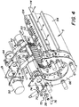
- a rotary printing system employing a multi-position lens assembly is illustrated in Figure 1, and includes a rotor 1 coupled to a drive motor, not shown, supported by a rotor support member 2 which hangs from a carriage assembly 3 which is supported for movement along a pair of guide rods 4 and 4'.
- the rotor is arranged to spin and move axially within a cylindrical support shoe 5 which is provided with a sheet of photosensitive material on the inner surface 6 thereof.
- Rotor 1 is attached to a linear translation assembly comprising rotor support member 2, carriage assembly 3, and a lead screw 7 driven by a stepper motor.
- the rotor is simultaneously rotated by the drive motor in a fast scan direction and is translated past the cylindrical support shoe in the slow scan direction (axially) by the stepper motor and lead screw 7, thereby achieving a raster scan pattern on the photosensitive media held within the support shoe.
- An LED printhead assembly 8 is mounted in rotor 1 and comprises a plurality of mono-color light sources such as an array of LED's and a projection lens assembly.
- the printhead assembly is located within the body of rotor 1 with the LED array package positioned so that the LED aperture output surface is located in a plane which is perpendicular to the optical axis of the projection lens assembly.
- the projection lens assembly is arranged to simultaneously image (focus) all of the LED's in the array onto a surface located in close proximity above the outer surface of the rotor, and more particularly, onto the inner surface of the photosensitive material held by support shoe 5.
- a single projection lens array thereby images the plurality of LED's onto the photosensitive material as a plurality of individual images which constitute the writing beams that expose the image pixels.
- a light-tight cassette 16 houses a roll 18 of photographic light sensitive media.
- Cassette 16 pivots about an axis 20.
- a flock-lined slit 22 in cassette 16 allows egress of media 24.
- Media 24 is fed around a shoe 26 made from a material with a low co-efficient of friction such as Delrin AF.
- Shoe 26 is allowed to pivot, that is, gimbal, about an axis 28. At the far end of shoe 26 is a rotatable flange which serves as an edge guide 30 against which media 24 abuts during transport.
- An anti-backup roller 32 is pivotally mounted to light-tight door 12. When door 12 is closed, anti-backup roller 32 urges media 24 against shoe 26. Anti-backup roller 32 also urges media 24 towards edge guide 30 as media 24 is advanced, as described below.
- a metering roller 34 with a covering of a material with a high coefficient of friction such as urethane, is supported on a metering roller shaft 36 by bearings 38 and 40.
- a pulley 44 At the end of shaft 36 is a pulley 44 which is rotatably driven by a stepper motor 50 which responds to control signals from a stepper motor driver circuit, not shown.
- metering roller 34 Situated about metering roller 34 is a series of pliable media guide belts 52 which are rotatably, but not drivenly, mounted to a corresponding set of guide belt pulleys 54. Media guide belts 52 also loop around grooves 56 located on a pressure roller 58, the outer diameter of which has a low coefficient of friction coating, such as for example Delrin AF or anodized aluminum. Pressure roller 58 urges media 24 into contact with metering roller 34.
- Pressure roller 58 is rotatably mounted on a pressure roller shaft 60, one end of which has a flat 62 that is pivotally limited by a slot 64 in an end cap 66 of cylindrical support shoe 5. Flat end 62 is further captured in a slot 68 in an adjustment plate 70. Adjustment plate 70 is rotatably arranged about bearing 38 for metering roller shaft 36. Adjustment is made by turning a set screw 72 which impinges on a stop 74 located on cylindrical support end cap 66. A spring 76 is arranged to bias flat end 62 against slot 68, to urge pressure roller 58 into metering roller 34, and to keep set screw 72 against stop 74. Adjustability is provided so that the axes of pressure roller 58 and metering roller 34 can be made parallel during assembly.
- pressure roller 58 maintains the nip between metering roller 34 and pressure roller 58 in an axially parallel condition regardless of forward or backward metering direction.
- Flat 62 and slot 68 interface keeps shaft 60 from rotating during metering.
- a round 80 is loosely captured by slot 82 in cylindrical support end cap 84.
- the round end is axially held by a retaining ring 86.
- a spring 88 is arranged to bias round end 80 against a flat edge of slot 82, and to urge pressure roller 58 into metering roller 34.
- media 24 is fed between metering roller 34 and media guide belts 52, causing media 24 to be drawn into the nip between metering roller 34 and pressure roller 58.
- the arrangement of these rollers is such that, when media 24 leaves the roller nip, the media is essentially tangent to the leading edge of cylindrical support shoe 5.
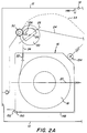
- cylindrical support shoe 5 is constructed so that numerous intermediate walls 92 and an outer wall 94 form individual triangularly-shaped manifold chambers A, B, C, D, and E, and non-manifold chambers 98, all of which contribute substantially to the self-rigidity of cylindrical support shoe 5.
- Two end caps (only end cap 66 is shown in Figure 4) are secured at each end of support shoe 5 and have holes 100 opening onto manifold chambers A to E, to which are attached means to selectively connect a vacuum source, not shown.
- the arcuate inner surface of cylindrical support shoe 5 is precisely bored so that illumination means, not shown, mounted on the rotor, focus on the emulsion side of media 24.
- the arcuate inner surface and bores for metering roller shaft 36 are bored on the same fixture so that their axes are parallel with each other.
- the arcuate inner surface of support shoe 5 has radial slots, best seen in Figure 4, which communicate the vacuum distributed by manifold chambers A to E to the back side of media 24. The vacuum intimately holds media 24 to the arcuate inner surface.
- the trailing edge of the arcuate inner surface is tangent to essentially cylindrical manifold chamber E, which is provided with radial slots to communicate the vacuum distributed by manifold chamber E to the back side of media 24.
- a first cutting edge 114 of a knife is attached to cylindrical support shoe 5.
- a second cutting edge 116 is slidably mounted to impinge upon first cutting edge 114 to thereby create knife means to separate a media sheet from media web 24.
- a translator base assembly 120 is attached via vibration absorbing mounts, not shown, to the framework of the light-tight cabinet 10 and supports guide rods 4 and 4'.
- Two sets of wheels 124 and 124' are rotatably attached to a carriage 126 which translates along guide rods 4 and 4' by means of lead screw 7 turned by a lead screw motor, not shown.
- Rotor support member 2 is rigidly attached to carriage 126, and carries a rotor 132 depicted by the dashed circle upon which is mounted the illumination means, not shown.
- a media guide member 134 that carries a plurality of rollers 136 angularly distributed around the periphery of media guide member 134.
- Rollers 136 are made from a lubricious material such as Delrin so as to be self lubricating and of low inertia, and are arranged such that a space gap is created between the outer diameter of rollers 136 and arcuate inner surface 6.
- the space gap is larger in diameter than rotor 132 so as to prevent media 24 from encountering rotor 132 during media transport operation or rotor translation.
- media exiting knife means 114, 116 is directed by a deflector 140 either to a waste container 142 or to the entry of a media transport assembly 144.
- Roll 18 of photographic light-sensitive media is loaded in cassette 16 in the dark so as not to expose the emulsion.
- a leader is fed through flock-lined slit 22.
- Light-tight door 12 is opened which defeats an interlock 146 ( Figure 2B) to electrically disconnect power to rotor 132 and to a carriage motor, not shown.
- Cassette 16 is then placed inside a cassette pan 148 ( Figure 2A) and urged inwards until a lip 150 of the cassette engages with a front lip 152 of pan 148. This engagement is maintained by a spring driven roller 154.
- An exposed leader of media 24 is pulled from the cassette, dressed over shoe 26, and urged into a guide way formed by media guide belt 52 and metering roller 34.
- a sensor means 158 signals the presence of media 24 in its location and signals metering roller 34 to drive in a clockwise direction. This has the effect of drawing media 24 into the nip between metering roller 34 and pressure roller 58.
- a second sensor means 160 is located downstream of the roller nip and turns off drive signals to metering roller 34 when the leading edge of media 24 is present.
- Carriage 126 carrying rotor support member 2 and rotor 132, is caused to translate along guide rods 4 and 4' until media guide member 134 is at a point approximately midway down the axis of the arcuate inner surface of support shoe 5.
- Metering roller 34 is rotated by stepper motor 50 in response to control signals which causes media 24 to be driven into the space gap created by rollers 136 of media guide member 134 and the cylindrical support surface of support shoe 5.
- lateral biasing action of anti-backup roller 32 urges media 24 into edge guide 30 ( Figure 2A) to provide a lateral constraint.
- Media 24 is angularly constrained by metering roller 34.
- the unconstrained leader end of media 24 will steer itself to a condition perpendicular to the axis of metering roller 34.
- media 24 is urged between the second set of media guide belts 112 and cylindrical manifold chamber E, and then past knife cutting edge 114.
- diverter 140 ( Figure 2C) is pivoted to the position shown by the broken lines. Media 24 is deflected towards waste container 142 as it is driven for a predetermined distance, dependent upon the number of stepping signals given to metering roller stepper motor 50.
- stepper motor 50 stops driving, vacuum is applied to manifold chamber C. This has the effect of drawing media 24 away from chambers A, B, D, and E as media 24 immediately adjacent chamber C is drawn into intimate contact with the arcuate inner surface, thus removing most of the slack in the segment of media 24 between metering roller 34 and chamber C. Vacuum is then applied to chamber A, which causes the media segment to become taut and in intimate contact with the arcuate inner surface. Vacuum to chamber C is then turned off. Vacuum to chamber B is initiated, then C, then D, then E. The sequential actuation of the chambers forces media 24 to wrap around arcuate inner surface 6 from metering roller 34 to first knife cutting edge 114, pushing air ahead of it. The "wiping" action prevents air bubbles from forming between the arcuate inner surface and the back surface of media 24.
- Knife cutting edge 116 is then slidably actuated to impinge upon and rotate about first cutting edge 114. This separates media 24 into a small sheet, which falls into waste container 142. Vacuum is discontinued to all chambers A to E, releasing the intimate bond to the arcuate inner surface of support shoe 5. Metering roller 34 is then driven another predetermined number of steps and the vacuum sequence described above is again initiated and followed by operation of the knife means. This occurs until all that portion of media 24 which was exposed during the loading operation is in waste container 142.
- diverter 140 When all exposed leader media is parted from media web 24, diverter 140 is de-energized, allowing it to pivot to the position shown by the solid lines in Figure 2C.
- Metering roller 34 is driven counter-clockwise the number of steps that corresponds to the arcuate length between cutting edge 114 and the end of the arcuate inner surface.
- a slack loop 33 depicted by dashed line in Figures 2A and 2B, is formed in the media between the entrance to metering roller 34 and the interface between gimbal shoe 26 and anti-backup roller 32. Space is provided within light-tight cabinet 10 for this purpose.
- a sequential vacuum is then applied in the manner described above. That is, first C, then A, etc.
- Carriage 126 is driven by lead screw 7 so that illumination means on rotor 132 are aligned with the edge of media 24 in the arcuate inner surface. Printing now occurs by moving carriage 126 down rods 4 and 4' while rotor 132 spins with the illumination means precisely exposing media 24 in response to signals delivered from image storage means, not shown.
- carriage 126 is caused to translate in a reverse direction along guide rods 4 and 4' until media guide member 134 is at a point approximately midway down the length of the arcuate inner surface axis. Vacuum is discontinued so media 24 can be moved. Metering roller 34 is driven so that the edge of media 24 crosses the top of diverter 140 and enters a space gate at entrance to media transport assembly 144. When media 24 has been driven into the space gate, the appropriate number of steps that corresponds to the image length plus the arcuate length between end of arcuate support 106 and cutting edge 114, vacuum is again sequentially initiated and the exposed portion is cut with knife means 114, 116.
- the image is over-written to assure that the image fills the exposable surface of media 24.
- vacuum is discontinued and media 24 is advanced a small number of steps corresponding to the over-written portion plus a minimal buffer amount to provide an unexposed edge for the ensuing print.
- Vacuum is drawn as stated above, and the over-write portion is severed from the web of media 24 by knife means 114, 116. The severed, unexposed edge is small enough to fit between knife means and diverter 140, so diverter 140 need not be actuated for the over-written portion to fall into waste container 142.
- Vacuum is again released, and media of a length corresponding to the distance between end of the arcuate inner surface and cutting edge 114 is again withdrawn onto the arcuate inner surface. Vacuum is re-applied in the manner described above and the ensuing exposure is made.
- Media guide member 134 is moved to the axial center of support shoe 5 and the leading edge of media web 24 is loaded into the nip of pressure roller 58 and metering roller 34. The web is moved past knife cutting edges 116 and 118 with deflector 140 in its dotted line position. Anti-backup roller 32 forces the web into lateral constraint edge guide 30.
- Vacuum is applied to hold the web to the shoe surface while an exposed portion of the web is trimmed.
- the vacuum is released, the web moved again, vacuum is re-applied, and another exposed portion of the web is trimmed. This is repeated until all exposed web has been removed.
- the vacuum is turned off and the web is moved back into the shoe past a "print” position.
- the web is moved forward in the shoe to its "print” position, and vacuum is applied and deflector 140 is returned to its illustrated full line position.
- Media guide member 134 is moved with the rotor while the media is exposed by printhead assembly 8.
- the vacuum is released and sheet transport assembly 144 is opened.
- the web is advanced to the sheet transport assembly until the trailing edge of the exposed portion of the media is at knife cutting edges 114, 116. Vacuum is applied before the web is cut.
- the cut sheet is driven down transport assembly 144 to a film processor, not shown, and the process is repeated for the next exposure.
- Figure 5 is a view similar to Figure 2B, showing another preferred embodiment of the present invention.
- the two embodiments are generally quite similar, but there are several distinctions to be noted herein.
- the embodiment of Figure 5 includes a cast or fabricated support shoe 180 rather than the extruded support shoe 5 of the first embodiment.
- Support shoe 180 includes a series of, say, two vacuum chambers (not shown) and an entrance chamber 182 with a series of perforations to communicate vacuum from the interior of the entrance chamber to the back side of the media.
- the embodiment of Figure 5 includes an exit roller mechanism 184 similar to the entrance roller 34 mechanism.
- the exit roller mechanism includes a driven roller 186 with a low coefficient of friction covering, a series of belts 188, and a movable pressure roller 190 which opens and closes the nip with exit roller 186.
- the embodiment of Figure 5 is suitable for use with larger format media than is the first embodiment; the exit roller mechanism being better at controlling movement of wider web.
- a vacuum box 192 provides the web control that was presented by chamber E of the first embodiment.
Landscapes
- Engineering & Computer Science (AREA)
- Multimedia (AREA)
- Signal Processing (AREA)
- Projection-Type Copiers In General (AREA)
- Handling Of Continuous Sheets Of Paper (AREA)
Priority Applications (3)
| Application Number | Priority Date | Filing Date | Title |
|---|---|---|---|
| CA002166760A CA2166760A1 (fr) | 1994-06-20 | 1996-01-08 | Raccord rapide pour tuyaux rainures |
| AU40871/96A AU4087196A (en) | 1994-06-20 | 1996-01-09 | Quick connect connector for grooved pipe |
| JP8018237A JPH09196272A (ja) | 1994-06-20 | 1996-01-10 | 溝付管用迅速作動形連結器 |
Applications Claiming Priority (2)
| Application Number | Priority Date | Filing Date | Title |
|---|---|---|---|
| US371241 | 1989-06-21 | ||
| US08/371,241 US5745157A (en) | 1995-01-11 | 1995-01-11 | Digital printer with support shoe and translatable media guide member therein |
Publications (3)
| Publication Number | Publication Date |
|---|---|
| EP0722243A2 true EP0722243A2 (fr) | 1996-07-17 |
| EP0722243A3 EP0722243A3 (fr) | 1996-11-13 |
| EP0722243B1 EP0722243B1 (fr) | 2001-06-27 |
Family
ID=23463121
Family Applications (1)
| Application Number | Title | Priority Date | Filing Date |
|---|---|---|---|
| EP96300195A Expired - Lifetime EP0722243B1 (fr) | 1994-06-20 | 1996-01-10 | Imprimeur numérique avec patin de support avec élément de guidage de médias translatables dans celui-ci |
Country Status (5)
| Country | Link |
|---|---|
| US (1) | US5745157A (fr) |
| EP (1) | EP0722243B1 (fr) |
| JP (1) | JPH08254770A (fr) |
| AU (1) | AU706782B2 (fr) |
| DE (1) | DE69613491T2 (fr) |
Families Citing this family (1)
| Publication number | Priority date | Publication date | Assignee | Title |
|---|---|---|---|---|
| JP7271260B2 (ja) * | 2019-03-29 | 2023-05-11 | ローム株式会社 | サーマルプリントヘッド |
Family Cites Families (19)
| Publication number | Priority date | Publication date | Assignee | Title |
|---|---|---|---|---|
| US2511892A (en) * | 1950-06-20 | Facsimile recording apparatus with | ||
| NL25671C (fr) * | 1927-04-07 | |||
| JPS5118138B1 (fr) * | 1969-07-31 | 1976-06-08 | ||
| US3925607A (en) * | 1974-08-21 | 1975-12-09 | Singer Co | Rotary data base converter with flexible data base |
| US3958250A (en) * | 1975-02-27 | 1976-05-18 | Sequential Data Machines, Inc. | Graphic plotting systems |
| US4334770A (en) * | 1978-12-22 | 1982-06-15 | Logetronics, Inc. | Method and apparatus for manipulating and transporting image media |
| JPS5587120A (en) * | 1978-12-23 | 1980-07-01 | Fuji Photo Film Co Ltd | Recorder |
| JPS5586265A (en) * | 1978-12-23 | 1980-06-28 | Fuji Photo Film Co Ltd | Recorder |
| US4293864A (en) * | 1980-01-24 | 1981-10-06 | The United States Of America As Represented By The Secretary Of The Army | Laser scanner transport |
| JPS57151933A (en) * | 1981-03-16 | 1982-09-20 | Fuji Photo Film Co Ltd | Laser rotary printer |
| US4479148A (en) * | 1982-06-02 | 1984-10-23 | Crosfield Data Systems, Inc. | Method and apparatus for insuring that the transport of a scanning system is contiguous with its support |
| DE3318311A1 (de) * | 1983-05-19 | 1984-11-22 | Dr. Böger Photosatz GmbH, 2000 Wedel | Optische lichtfleck-abtastvorrichtung fuer ein photoempfindliches bahnmaterial bei optischen photosetzgeraeten |
| US4678312A (en) * | 1983-08-01 | 1987-07-07 | Fuji Photo Film Co., Ltd. | Rotatable head type electrophotographic apparatus, corona charging rotatable head and moveable electrophotographic liquid development processing unit therefor |
| FR2571198B1 (fr) * | 1984-09-28 | 1987-01-09 | Europ Propulsion | Restituteur d'images haute resolution autorisant le developpement en temps reel des films insoles |
| JPS6292572A (ja) * | 1985-10-17 | 1987-04-28 | Fuji Photo Film Co Ltd | 光ビ−ム走査装置 |
| US4698647A (en) * | 1986-05-13 | 1987-10-06 | Truvel Corporation | High resolution photographic film printer |
| DE3888842T2 (de) * | 1988-12-15 | 1994-10-06 | Agfa Gevaert Nv | Bildreproduktionsapparat. |
| US5097351A (en) * | 1990-08-06 | 1992-03-17 | Holotek, Ltd. | Simultaneous multibeam scanning system |
| US5214528A (en) * | 1990-09-14 | 1993-05-25 | Konica Corporation | Optical beam scanning apparatus |
-
1995
- 1995-01-11 US US08/371,241 patent/US5745157A/en not_active Expired - Fee Related
-
1996
- 1996-01-10 AU AU40906/96A patent/AU706782B2/en not_active Ceased
- 1996-01-10 DE DE69613491T patent/DE69613491T2/de not_active Expired - Fee Related
- 1996-01-10 EP EP96300195A patent/EP0722243B1/fr not_active Expired - Lifetime
- 1996-01-10 JP JP8002628A patent/JPH08254770A/ja active Pending
Also Published As
| Publication number | Publication date |
|---|---|
| JPH08254770A (ja) | 1996-10-01 |
| US5745157A (en) | 1998-04-28 |
| EP0722243B1 (fr) | 2001-06-27 |
| EP0722243A3 (fr) | 1996-11-13 |
| DE69613491D1 (de) | 2001-08-02 |
| DE69613491T2 (de) | 2002-04-25 |
| AU4090696A (en) | 1996-07-18 |
| AU706782B2 (en) | 1999-06-24 |
Similar Documents
| Publication | Publication Date | Title |
|---|---|---|
| US6238113B1 (en) | Media feed apparatus for imaging system | |
| US6204871B1 (en) | Recording drum arrangement | |
| AU706782B2 (en) | Digital printer with support shoe and translatable media guide member therein | |
| EP0722245B1 (fr) | Imprimeur avec patin de support à vide avec élément de coupure de médias dans celui-ci | |
| US6240260B1 (en) | Method and apparatus for buffer transfer of media sheets between components in an imagesetting system | |
| US5751334A (en) | Printer with support shoe and media metering therein | |
| US5173731A (en) | Recording apparatus | |
| EP0722114A2 (fr) | Imprimante avec patin de support et élément de guidage des moyens à la sortie | |
| US5668645A (en) | Method and apparatus for printing films | |
| JPS61114950A (ja) | シ−ト巻取装置 | |
| JP3628456B2 (ja) | 画像記録装置 | |
| JP3529211B2 (ja) | 画像位置情報の形成方法 | |
| US5661545A (en) | Strip recording media exposure using a rotating drum recorder | |
| EP0751667A2 (fr) | Exposition d'un moyen de reproduction en forme de bande en utilisant un tambour de reproduction tournant | |
| JP3634910B2 (ja) | 画像記録装置 | |
| JP2005179003A (ja) | 画像形成装置 | |
| JPH0372334A (ja) | マイクロフィルムへの画像記録装置 | |
| JPS5983456A (ja) | レ−ザ記録装置 | |
| JPS6351262A (ja) | 画像記録担体用供給機構 | |
| JPH0275558A (ja) | ニップローラクローズ機構 | |
| JPH04296851A (ja) | ロール紙巻取り装置 | |
| JPH03100641A (ja) | マイクロフィルムへの画像記録装置 | |
| JPH09197568A (ja) | 走査面シャッタ機構 | |
| JPH10338401A (ja) | 記録装置 | |
| JPH0372335A (ja) | マイクロフィルムへの画像記録装置 |
Legal Events
| Date | Code | Title | Description |
|---|---|---|---|
| PUAI | Public reference made under article 153(3) epc to a published international application that has entered the european phase |
Free format text: ORIGINAL CODE: 0009012 |
|
| AK | Designated contracting states |
Kind code of ref document: A2 Designated state(s): CH DE FR GB IT LI |
|
| PUAL | Search report despatched |
Free format text: ORIGINAL CODE: 0009013 |
|
| AK | Designated contracting states |
Kind code of ref document: A3 Designated state(s): CH DE FR GB IT LI |
|
| 17P | Request for examination filed |
Effective date: 19970418 |
|
| 17Q | First examination report despatched |
Effective date: 19990701 |
|
| GRAG | Despatch of communication of intention to grant |
Free format text: ORIGINAL CODE: EPIDOS AGRA |
|
| GRAG | Despatch of communication of intention to grant |
Free format text: ORIGINAL CODE: EPIDOS AGRA |
|
| GRAH | Despatch of communication of intention to grant a patent |
Free format text: ORIGINAL CODE: EPIDOS IGRA |
|
| GRAH | Despatch of communication of intention to grant a patent |
Free format text: ORIGINAL CODE: EPIDOS IGRA |
|
| GRAA | (expected) grant |
Free format text: ORIGINAL CODE: 0009210 |
|
| AK | Designated contracting states |
Kind code of ref document: B1 Designated state(s): CH DE FR GB IT LI |
|
| REG | Reference to a national code |
Ref country code: CH Ref legal event code: EP |
|
| ITF | It: translation for a ep patent filed | ||
| REF | Corresponds to: |
Ref document number: 69613491 Country of ref document: DE Date of ref document: 20010802 |
|
| REG | Reference to a national code |
Ref country code: CH Ref legal event code: NV Representative=s name: KIRKER & CIE SA |
|
| ET | Fr: translation filed | ||
| REG | Reference to a national code |
Ref country code: GB Ref legal event code: IF02 |
|
| PLBE | No opposition filed within time limit |
Free format text: ORIGINAL CODE: 0009261 |
|
| 26N | No opposition filed | ||
| PGFP | Annual fee paid to national office [announced via postgrant information from national office to epo] |
Ref country code: GB Payment date: 20021210 Year of fee payment: 8 |
|
| PGFP | Annual fee paid to national office [announced via postgrant information from national office to epo] |
Ref country code: FR Payment date: 20030107 Year of fee payment: 8 |
|
| PGFP | Annual fee paid to national office [announced via postgrant information from national office to epo] |
Ref country code: DE Payment date: 20030131 Year of fee payment: 8 |
|
| PGFP | Annual fee paid to national office [announced via postgrant information from national office to epo] |
Ref country code: CH Payment date: 20030319 Year of fee payment: 8 |
|
| PG25 | Lapsed in a contracting state [announced via postgrant information from national office to epo] |
Ref country code: GB Free format text: LAPSE BECAUSE OF NON-PAYMENT OF DUE FEES Effective date: 20040110 |
|
| PG25 | Lapsed in a contracting state [announced via postgrant information from national office to epo] |
Ref country code: LI Free format text: LAPSE BECAUSE OF NON-PAYMENT OF DUE FEES Effective date: 20040131 Ref country code: CH Free format text: LAPSE BECAUSE OF NON-PAYMENT OF DUE FEES Effective date: 20040131 |
|
| PG25 | Lapsed in a contracting state [announced via postgrant information from national office to epo] |
Ref country code: DE Free format text: LAPSE BECAUSE OF NON-PAYMENT OF DUE FEES Effective date: 20040803 |
|
| GBPC | Gb: european patent ceased through non-payment of renewal fee |
Effective date: 20040110 |
|
| REG | Reference to a national code |
Ref country code: CH Ref legal event code: PL |
|
| PG25 | Lapsed in a contracting state [announced via postgrant information from national office to epo] |
Ref country code: FR Free format text: LAPSE BECAUSE OF NON-PAYMENT OF DUE FEES Effective date: 20040930 |
|
| REG | Reference to a national code |
Ref country code: FR Ref legal event code: ST |
|
| PG25 | Lapsed in a contracting state [announced via postgrant information from national office to epo] |
Ref country code: IT Free format text: LAPSE BECAUSE OF NON-PAYMENT OF DUE FEES;WARNING: LAPSES OF ITALIAN PATENTS WITH EFFECTIVE DATE BEFORE 2007 MAY HAVE OCCURRED AT ANY TIME BEFORE 2007. THE CORRECT EFFECTIVE DATE MAY BE DIFFERENT FROM THE ONE RECORDED. Effective date: 20050110 |