EP0722654B1 - Appareil de traitement à bras porteur pour l'entretien des accotements routiers - Google Patents
Appareil de traitement à bras porteur pour l'entretien des accotements routiers Download PDFInfo
- Publication number
- EP0722654B1 EP0722654B1 EP96100849A EP96100849A EP0722654B1 EP 0722654 B1 EP0722654 B1 EP 0722654B1 EP 96100849 A EP96100849 A EP 96100849A EP 96100849 A EP96100849 A EP 96100849A EP 0722654 B1 EP0722654 B1 EP 0722654B1
- Authority
- EP
- European Patent Office
- Prior art keywords
- boom
- sensor arrangement
- setting
- implement according
- changes
- Prior art date
- Legal status (The legal status is an assumption and is not a legal conclusion. Google has not performed a legal analysis and makes no representation as to the accuracy of the status listed.)
- Expired - Lifetime
Links
- 238000012423 maintenance Methods 0.000 title claims description 4
- 230000001105 regulatory effect Effects 0.000 claims abstract 8
- 238000012937 correction Methods 0.000 claims description 4
- 238000006073 displacement reaction Methods 0.000 claims description 4
- 238000010586 diagram Methods 0.000 description 6
- 230000008859 change Effects 0.000 description 4
- 229910000639 Spring steel Inorganic materials 0.000 description 3
- 238000013461 design Methods 0.000 description 3
- 238000005516 engineering process Methods 0.000 description 2
- 238000000034 method Methods 0.000 description 2
- 230000008569 process Effects 0.000 description 2
- 238000005096 rolling process Methods 0.000 description 2
- 239000000523 sample Substances 0.000 description 2
- 230000002123 temporal effect Effects 0.000 description 2
- 244000025254 Cannabis sativa Species 0.000 description 1
- 208000033999 Device damage Diseases 0.000 description 1
- 230000003213 activating effect Effects 0.000 description 1
- 230000004913 activation Effects 0.000 description 1
- 230000006978 adaptation Effects 0.000 description 1
- 230000008878 coupling Effects 0.000 description 1
- 238000010168 coupling process Methods 0.000 description 1
- 238000005859 coupling reaction Methods 0.000 description 1
- 238000011161 development Methods 0.000 description 1
- 230000018109 developmental process Effects 0.000 description 1
- 239000012530 fluid Substances 0.000 description 1
- 238000003754 machining Methods 0.000 description 1
- 239000000463 material Substances 0.000 description 1
- 230000003287 optical effect Effects 0.000 description 1
- 238000012545 processing Methods 0.000 description 1
- 230000007363 regulatory process Effects 0.000 description 1
- 239000000725 suspension Substances 0.000 description 1
Images


Classifications
-
- E—FIXED CONSTRUCTIONS
- E02—HYDRAULIC ENGINEERING; FOUNDATIONS; SOIL SHIFTING
- E02F—DREDGING; SOIL-SHIFTING
- E02F5/00—Dredgers or soil-shifting machines for special purposes
- E02F5/28—Dredgers or soil-shifting machines for special purposes for cleaning watercourses or other ways
- E02F5/282—Dredgers or soil-shifting machines for special purposes for cleaning watercourses or other ways with rotating cutting or digging tools
-
- A—HUMAN NECESSITIES
- A01—AGRICULTURE; FORESTRY; ANIMAL HUSBANDRY; HUNTING; TRAPPING; FISHING
- A01D—HARVESTING; MOWING
- A01D34/00—Mowers; Mowing apparatus of harvesters
- A01D34/835—Mowers; Mowing apparatus of harvesters specially adapted for particular purposes
- A01D34/86—Mowers; Mowing apparatus of harvesters specially adapted for particular purposes for use on sloping ground, e.g. on embankments or in ditches
Definitions
- the invention relates to a mobile boom implement for street maintenance, in particular Boom mower with a device for boom relief control according to changes of the Working head, especially mowing head encountered resistance depending on signals from a sensor arrangement, where on separate boom and side adjustment drives to adjust the boom in its height and lateral pivot position are provided, and the Lift drive of the boom under the control of the Sensor signals in the context of a control loop, which is Changes in the resistance of the working head from the sensor arrangement a disturbance variable of the control variable is supplied to which the control loop with a appropriate manipulated variable to correct the height of the Boom reacts through its lifting drive (according to the Preamble of claim 1).
- Boom mowers of the design mentioned here have been used successfully for many years and especially known from DE-PS 21 59 944. In its they were originally addressed with one of the Operator-operated control for the Height position of the boom equipped.
- the boom relief regulation addressed in the preamble of claim 1 is the subject of the older, not Pre-published patent application P 44 01 716.2.
- this older device in which the housing of the working head by an essentially parallel roller on the floor Ground is supported and to influence the Contact pressure of the rolling roller on the site Boom in the actuator Proportionally controllable pressure relief valve assigned is, it is provided that for the scanning of vertical Movements of the unrolling roller with its displacement sensor arrangement Probe head in direct drive connection with the unwind roller stands.
- the roller is in the housing of the Working head with its axis at the free end of one cantilevered spring steel arrangement suspended and stands the sensor probe at the point of suspension in touch with the spring steel.
- the invention is based on the object mobile boom implement of the type in question with to provide a simple boom relief regulation, which without sensor arrangements arranged on the working head gets along and possibly also a simple assembly of a Unroll roller enables.
- the sensor arrangement for the swivel position of the bogie of the boom can also as Pressure transducers on the swivel cylinder, and also optical sensor arrangements with scanning of position markings are possible.
- Boom implements according to DE-PS 32 18 525 already have one Coupling between a hydraulic lifting cylinder for the Outrigger and one the outrigger in its side Hydraulic cylinder holding the pivot position in such a way it is provided that by resistance caused pivoting of the boom about its vertical Axis and a related extension of the Piston rod associated with the swivel position Hydraulic cylinder the first-mentioned hydraulic lifting cylinder acted on in the sense of swinging the boom becomes.
- This arrangement is effective as overload protection, so that when there is resistance on the embankment mower swing out its main beam together with the embankment mower can to avoid device damage. Once the If resistance disappears, the embankment mower can come back in to be transferred to its normal position.
- Such an arrangement does not, however, permit constant adaptation of the Contact pressure of the working head according to the constantly changing working conditions, as they are by themselves changing terrain inclination, changed driving speed, Changes in the resistance of the processed material (thinner, thicker, wetter, drier grass) etc. are produced.
- Fig. 1 shows a top view of a mobile Boom working device with a working head in the form of a Mowing head, which can be pivoted on a bogie Boom sits.
- Fig. 2 shows such a device from behind with side stretched mower head boom.
- Fig. 3. shows a schematic partial side view of a Bogie with boom and lifting cylinder, with the mowing head is omitted from the boom and schematically the Influencing variables of a control loop for the relief of the boom are indicated.
- Fig. 4 shows a partial plan view of the boom bogie 3 with a switch cam and Limit switch arrangement for detecting changes in the Swivel angle in the bogie.
- Fig. 5 shows a block diagram of a boom relief control based on one of the Switch cam and limit switch arrangement on the bogie as Sensor arrangement emitted interference.
- Fig. 1 shows a mobile boom implement for Street maintenance work in the form of a Boom mower.
- A sits on the carrier vehicle T.
- Boom A which carries a mower head M in a known manner.
- a bogie D and a swivel cylinder SZ the boom A with the mowing head M carried by it different swivel positions can be set.
- For the normal mowing is essentially the boom swung out laterally at a right angle, whereby for one Processing possibility on one or the other A swivel range of approximately 200 ° is provided on the street side.
- Fig. 2 also illustrates the bogie D for the Boom A and also a lifting cylinder H by means of which the Boom A with the mowing head M on it as required can be raised or lowered.
- Figure 2 also leaves one Detect unroll roller AW with which the mowing head on the site is supported.
- Control circuit ensures that on the basis of an in Control unit 1 using a rotary potentiometer DP adjustable setpoint W as the reference variable of the control loop a constant readjustment of the height of the boom A oriented to the setpoint.
- One sensor arrangement is used by a Pressure sensor U / P formed on the lifting cylinder H des Boom A is provided and the actual value of the pressure in Determines the lifting cylinder, which is the controlled variable X of the Control loop according to external influences, such as encountered terrain inclinations and also in accordance with that of the control group for the necessary corrections adjustments made to the pressure in the lifting cylinder H changes.
- the other sensor arrangement which is the control loop influenced, speaks to changes in the pivoting position of the Boom A as they increased when they occurred Mowing resistance or the like. Because of such increased Resistance seeks outrigger A and mower head M to let it fall back a little against the direction of travel and thus to change the swivel position.
- changes in the swing position of the boom 4 shows an arrangement of switching cams S and Limit switch E provided. If the rotational position of the Bogie D with the boom A attached to it, see above the limit switch E can run onto the switching cams S and give an appropriate signal.
- Sensor arrangement for the swivel position of the bogie D of the boom A can also sensor arrangements in Shape of a pressure or displacement sensor on the swivel cylinder SZ or also those with scanning position markers Bogie or swivel cylinder as in Figure 4 schematically at "Alt.” indicated use.
- the control circuit shown in Figure 5 for the Boom relief is based on the lifting cylinder H of the boom formed actuator.
- the lifting cylinder H forms according to him for the adjustment of the Height of the boom by means of a hydraulic Control valve supplied hydraulic fluid hydraulic pressure, the actual value of which by means of Pressure transducer U / P measured as a sensor arrangement and by the control loop is changed as controlled variable X if at Changes in the height of the boom due to external Influences a disturbance variable Z1 occurs.
- the hydraulic pressure in the lifting cylinder is used as the controlled variable X fed to a comparator 2, which is also used as a reference variable the one set on the rotary potentiometer DP in the control panel Setpoint W is supplied.
- the comparator provides the Control difference Xd fixed, which is fed to a controller 3 and as whose output signal YR is fed to an addition point 9 becomes.
- This addition point 9 also receives a manipulated variable Y2 supplied, which is delivered by a ramp generator 6, the in turn input signals from the sensor arrangement Limit switch E and switch cam S (in Figure 5 in block 5) receives if due to the changed pivot position of the Bogie D occurs a disturbance Z2.
- the by the ramp generator 6 based on the Sensor arrangement 5 from switch cam SZ and limit switch E The manipulated variable formed Y2 also becomes at the branch point 10 an actuator 8 of the pivot cylinder S passed to Changes in the swivel position of the bogie D correct the boom and the boom in its Reset normal position.
- the present boom relief regulation provides one Combination of control and regulation, in which one Activation of detected by means of a sensor arrangement Disturbances occur. Is by the sensor arrangement U / P on Lift cylinder H for the height position of the boom one Disturbance Z1 cannot be measured, the control loop can be additional timing chain including the sensor arrangement (Switch cam S - limit switch E) for the swivel position of the Affect bogie D. By activating the Disturbance Z2 of this sensor arrangement via a ramp generator 6 on the manipulated variable at output YR of controller 3 is by the resulting manipulated variable Y1 is the actual interference balanced.
- the operation of the boom relief control can be represent as follows:
- the setpoint generator W (rotary potentiometer) specifies the value that should be achieved in the controlled system.
- the controller 3 has the task of the control difference signal reinforce and shape so that it continues as manipulated variable Y1 at the entrance of controlled system 4 the actuator (Hubyzlinder H Can raise / lower).
- This signal circuit from the output of the controlled system 4 via the comparison point 2 control device 3 to the actuator on The input of the controlled system is effective until the Actual value X is in the insensitivity zone of setpoint W located.
- a large insensitivity zone leads to a stable one Control process, but can be a large permanent control deviation cause.
- the disturbance variable Z1 (boom height position, as recorded) makes noticeable at the measuring point for the controlled variable X.
- the Measured value of the controlled variable corrects the control difference Xd. Becomes thereby exceeding or falling below the insensitivity zone, the manipulated variable Y1 is corrected.
- the disturbance variable Z2 (detected change in the swivel position of the Bogie) is by the limit switch E Sensor arrangement 5 detected in the bogie.
- the disturbance variable Z2 changes according to the change in Swivel position of the bogie, so it makes itself new Value at controller input 3 noticeable and prompted (if Insensitivity zone exceeded or fallen below) one Change of manipulated variable Y1.
- a ramp generator 6 is used directly influencing the manipulated variable Y2 or the actuator 8 on the swivel cylinder SZ for the rotating position of the boom.
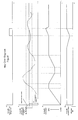
- the path-time diagram of Figure 6 illustrates how the combined control u. Regulatory process for the Boom relief by means of those explained above Device expires. It is in the upper area of the path-time diagram the occurrence of a disturbance variable Z2 on the off Switch cams S and limit switches E existing sensor arrangement and underneath the impact of lifting the Lift cylinder H shown for the boom. Also the Return of the temporarily adjusted boom A to his The normal position is in the lower area of the path-time diagram shown.
Landscapes
- Engineering & Computer Science (AREA)
- General Engineering & Computer Science (AREA)
- Environmental Sciences (AREA)
- Mechanical Engineering (AREA)
- Mining & Mineral Resources (AREA)
- Civil Engineering (AREA)
- Life Sciences & Earth Sciences (AREA)
- Structural Engineering (AREA)
- Harvester Elements (AREA)
- Jib Cranes (AREA)
- Lifting Devices For Agricultural Implements (AREA)
- Forklifts And Lifting Vehicles (AREA)
- Operation Control Of Excavators (AREA)
Claims (9)
- Appareil de travail à bras porteur mobile pour travaux d'entretien sur la chaussée, en particulier, une faucheuse avec un dispositif pour le réglage de la décharge du bras porteur, en fonction des modifications de la résistance rencontrée par la tête de travail, en particulier par la tête faucheuse (11), en fonction de signaux d'un dispositif à capteurs, sur le bras porteur (1), des entraínements de levage et de basculement étant prévus pour le déplacement du bras porteur dans sa position en hauteur et sa position latérale de pivotement et l'entraínement de levage du bras porteur étant commandé par les signaux de capteurs dans le cadre d'un circuit de réglage qui reçoit au moment des modifications de la résistance appliquée à la tête de travail une grandeur perturbatrice de la grandeur de réglage envoyée par le dispositif à capteur, grandeur à laquelle réagit le circuit de réglage avec une grandeur de réglage correspondante pour la correction de la position en hauteur du bras porteur par son entraínement de levage, caractérisé en ce que
le circuit de réglage présente pour la décharge du bras porteur 'a) un dispositif à capteur (5 respectivement Alt.) réagissant à des modifications de la position en hauteur du bras porteur par une grandeur perturbatrice (Z2),
présente également un autre dispositif à capteur (U/P) sur le vérin de levage (H) qui réagit aux modifications de la position en hauteur du bras porteur par une grandeur perturbatrice (Z1), en fonction des grandeurs perturbatrices (Z1 et Z2) deux grandeurs de réglage (Y1 et Y2) étant générées dont l'une (Y1) est amenée à l'organe de réglage, entraínement de levage (H) pour la décharge du bras porteur, tandis que l'autre grandeur de réglage (Y2) est amenée à l'organe de réglage, entraínement pivotant (SZ), pour le réglage du bras porteur dans sa position latérale normale. - Appareil de travail à bras porteur selon la revendication 1, caractérisé en ce qu'un dispositif à capteur (S, E) est prévu pour le balayage de la position d'un bâti tournant (D) du bras (A), en particulier un dispositif (S, E) d'interrupteur de fin de course et de came de commande (S, E) qui réagit à des modifications de la position de pivotement latérale du bras par une grandeur perturbatrice correspondante (Z2).
- Appareil de travail à bras porteur selon la revendication 1 ou 2, caractérisé en ce qu'un point d'addition (9) est prévu pour la superposition respectivement l'accumulation d'un signal (Y2) de l'interrupteur de fin de course (E) pour la position du bâti tournant avec le signal de sortie (YR) d'un régulateur (3), qui reçoit côté entrée une différence de réglage (xd) qui forme un système de comparaison (2) entre la valeur de consigne (W) réglable côté opérateur pour la position en hauteur du bras et une grandeur de réglage (X) qui est absorbée au moyen d'un absorbeur de pression (U/P) sur le vérin de levage (H) du bras (A), le point d'addition (9) délivrant la grandeur de réglage (Y1) pour la correction de la position en hauteur du vérin de levage (H).
- Appareil de travail à bras porteur selon la revendication 3, caractérisé en ce que le régulateur (3) est un régulateur par plus ou moins qui délivre selon trois états de commande à la détermination de la différence de réglage (xd), une grandeur de sortie (a) pour le levage du bras (A), une grandeur de sortie (o) dans une zone d'insensibilité et une grande de sortie (b) pour l'abaissement du bras (A).
- Appareil de travail à bras porteur selon la revendication 4, caractérisé en ce que la came de commande (S) recouvre sur le bâti tournant (D) une zone de position normale de la position de pivotement de l'arbre (A), en ce qu'au moment où le bras quitte cette zone de position, l'interrupteur de fin de course (E) se déclenche et émettant la grandeur perturbatrice (22).
- Appareil de travail à bras support selon une ou plusieurs des revendications précédentes, caractérisé en ce que le signal de réglage (Y1) pour la position en hauteur du bras porteur est amené à une soupape de réglage hydraulique du vérin de levage (H).
- Appareil de travail à bras support selon une ou plusieurs des revendications précédentes, caractérisé par un potentiomètre rotatif (DP) sur la partie de commande.
- Appareil de travail à bras support selon une ou plusieurs des revendications 3 - 7, caractérisé en ce que la grandeur de réglage (Y2) forme le signal de sortie du dispositif à capteur (5 respectivement Alt.) pour la position de pivotement du bâti tournant (D) du bras porteur au moyen d'une formation de rampe (6).
- Appareil de travail à bras support selon une ou plusieurs des revendications précédentes, caractérisé en ce qu'en tant que dispositif à capteurs pour la position latérale de pivotement du bras à la place d'un interrupteur de fin de course, on se sert d'un absorbeur de pression (Alt.) prévu sur un vérin de pivotement (SZ) du bâti tournant.
Applications Claiming Priority (2)
| Application Number | Priority Date | Filing Date | Title |
|---|---|---|---|
| DE19501903 | 1995-01-23 | ||
| DE19501903A DE19501903C1 (de) | 1995-01-23 | 1995-01-23 | Fahrbares Ausleger-Arbeitsgerät für Unterhaltungsarbeiten im Straßenbereich |
Publications (2)
| Publication Number | Publication Date |
|---|---|
| EP0722654A1 EP0722654A1 (fr) | 1996-07-24 |
| EP0722654B1 true EP0722654B1 (fr) | 2000-04-12 |
Family
ID=7752080
Family Applications (1)
| Application Number | Title | Priority Date | Filing Date |
|---|---|---|---|
| EP96100849A Expired - Lifetime EP0722654B1 (fr) | 1995-01-23 | 1996-01-22 | Appareil de traitement à bras porteur pour l'entretien des accotements routiers |
Country Status (3)
| Country | Link |
|---|---|
| EP (1) | EP0722654B1 (fr) |
| AT (1) | ATE191605T1 (fr) |
| DE (2) | DE19501903C1 (fr) |
Families Citing this family (12)
| Publication number | Priority date | Publication date | Assignee | Title |
|---|---|---|---|---|
| DE29907728U1 (de) * | 1999-04-30 | 2000-09-14 | Gerhard Dücker GmbH & Co. KG Landmaschinenfabrik, 48703 Stadtlohn | Mähgerät |
| GB9912266D0 (en) * | 1999-05-27 | 1999-07-28 | Spearhead Machinery Ltd | Improvements in implement control |
| RU2239684C2 (ru) * | 1999-06-15 | 2004-11-10 | Государственное унитарное предприятие Калужский завод "Ремпутьмаш" | Путевая машина |
| DE29919432U1 (de) * | 1999-11-04 | 2001-03-15 | Gerhard Dücker GmbH & Co. KG Landmaschinenfabrik, 48703 Stadtlohn | Mähgerät |
| EP1716735B1 (fr) * | 2005-04-25 | 2014-11-19 | MULAG Fahrzeugwerk Heinz Wössner GmbH & Co. KG | Prodédé et dispositif pour le réglage de la hauteur |
| DE102006019107B4 (de) * | 2005-04-25 | 2015-04-09 | Mulag Fahrzeugwerk Heinz Wössner GmbH u. Co KG | Verfahren und Vorrichtung zur Höhensteuerung |
| ITBO20050642A1 (it) * | 2005-10-24 | 2007-04-25 | Ferri Srl | Dispositivo e metodo di controllo per il mezzo di supporto di un attrezzo |
| ITBO20090654A1 (it) * | 2009-10-09 | 2011-04-10 | Ferri Srl | Dispositivo di sicurezza per braccio articolato |
| FR2967011B1 (fr) * | 2010-11-10 | 2013-11-22 | Kuhn Audureau Sa | Faucheuse-debroussailleuse avec des verins hydrauliques a gestion electronique |
| TWI665107B (zh) | 2017-12-12 | 2019-07-11 | 財團法人工業技術研究院 | 行動載具、地面處理機具及其姿態調整方法 |
| CN109162471B (zh) * | 2018-08-09 | 2020-09-18 | 东阳市琰安建筑工程有限公司 | 一种建筑外墙清洗装置 |
| CN109826268B (zh) * | 2019-01-10 | 2021-04-06 | 浙江海洋大学 | 具有疏浚泥削碎功能的航道疏浚装置 |
Family Cites Families (9)
| Publication number | Priority date | Publication date | Assignee | Title |
|---|---|---|---|---|
| BE792147A (fr) * | 1971-12-03 | 1973-03-16 | Mulag Fahrzeug Woessner | Engin faucheur aspirateur |
| US3949539A (en) * | 1971-12-22 | 1976-04-13 | Cartner Jack O | Hydraulic mower attachment |
| DE3218525C2 (de) * | 1982-05-17 | 1986-01-16 | Gerhard Dücker KG Landmaschinenfabrik, 4424 Stadtlohn | Böschungsmähgerät |
| GB2129265B (en) * | 1982-11-02 | 1986-03-26 | Turner Int | Mowers |
| GB8706756D0 (en) * | 1987-03-21 | 1987-04-23 | Mcconnel F W Ltd | Vegetation cutting apparatus |
| FR2642797B1 (fr) * | 1989-01-10 | 1991-05-17 | Secmair | Dispositif d'asservissement de la pression d'appui au sol d'un rouleau equipant une tete de coupe, notamment de fauchage |
| GB9100609D0 (en) * | 1991-01-11 | 1991-02-27 | Altimeter The Trust | Mowers |
| DE4401716C2 (de) * | 1994-01-21 | 1999-08-19 | Mulag Fahrzeug Woessner | Ausleger-Arbeitsgerät, insbesondere Ausleger-Mähgerät mit reichweiten-unabhängiger Stelleinrichtung für den Auflagedruck auf dem bearbeiteten Gelände |
| DE9400992U1 (de) * | 1994-01-21 | 1994-08-04 | Mulag Fahrzeugwerk Heinz Wössner GmbH u. Co KG, 77740 Bad Peterstal-Griesbach | Ausleger-Arbeitsgerät, insbesondere Auslegermähgerät mit Auflagedruck-Stelleinrichtung |
-
1995
- 1995-01-23 DE DE19501903A patent/DE19501903C1/de not_active Expired - Fee Related
-
1996
- 1996-01-22 EP EP96100849A patent/EP0722654B1/fr not_active Expired - Lifetime
- 1996-01-22 DE DE59604926T patent/DE59604926D1/de not_active Expired - Fee Related
- 1996-01-22 AT AT96100849T patent/ATE191605T1/de not_active IP Right Cessation
Also Published As
| Publication number | Publication date |
|---|---|
| EP0722654A1 (fr) | 1996-07-24 |
| ATE191605T1 (de) | 2000-04-15 |
| DE59604926D1 (de) | 2000-05-18 |
| DE19501903C1 (de) | 1996-07-25 |
Similar Documents
| Publication | Publication Date | Title |
|---|---|---|
| EP3420797B1 (fr) | Outil de coupe composé de plusieurs sections pourvu de protection antipliure et procédé de réglage en hauteur de l'outil de coupe | |
| DE602004004297T2 (de) | System und Verfahren für die Rollregelung eines aufgehängten Gestänges | |
| EP0722654B1 (fr) | Appareil de traitement à bras porteur pour l'entretien des accotements routiers | |
| DE10011498B4 (de) | Vorrichtung zur Bodenkopierung für Vorsatzgeräte an Erntemaschinen | |
| EP3378823B1 (fr) | Grue | |
| DE3604519C2 (fr) | ||
| DE3005741A1 (de) | Automatische positionssteuervorrichtung fuer das arbeitsgeraet eines erdarbeitsfahrzeugs | |
| DE102020110742A1 (de) | Einstellradhöhensteuerung für eine Erntegutbergungseinrichtung | |
| DE102014018133B4 (de) | Heuwerbungsmaschine | |
| EP3165090B1 (fr) | Système de commande et/ou de réglage d'une machine agricole | |
| EP0786200B1 (fr) | Dispositif et méthode de régulation de position d'une unité de travail d'une machine agricole | |
| EP1762535B1 (fr) | Engin roulant du type muni d'un bras et procédé pour celui-ci | |
| DE3827273A1 (de) | Verfahren und vorrichtung zum steuern eines vorganges nach einer konfiguration eines flaechigen oder raeumlichen gebildes nahe dem erdboden | |
| EP2710869B1 (fr) | Dispositif porte-outils frontal d'un véhicule de travail | |
| EP3987928B1 (fr) | Appareil agricole doté d'une rampe | |
| DE19921761B4 (de) | Verfahren und Vorrichtung zum Verstellen des Arbeitsabstandes | |
| DE69107751T2 (de) | Elektronische Vorrichtung zum Steuern der Arbeitstiefe und des Hebens eines Aufsatteldrehpfluges. | |
| DE4401716C2 (de) | Ausleger-Arbeitsgerät, insbesondere Ausleger-Mähgerät mit reichweiten-unabhängiger Stelleinrichtung für den Auflagedruck auf dem bearbeiteten Gelände | |
| DE29514953U1 (de) | Fahrbares Ausleger-Arbeitsgerät für Unterhaltungsarbeiten im Straßenverkehr | |
| EP0465790A1 (fr) | Faucheuse rotative pour l'attelage frontal à un tracteur | |
| WO2001065918A1 (fr) | Dispositif pour la reproduction du sol destine a des outils adaptables de moissonneuses | |
| DE2443477C2 (de) | Regeleinrichtung zur Neigungseinstellung für eine Erdbewegungsmaschine | |
| DE29908429U1 (de) | Vorrichtung zum Verstellen des Arbeitsabstandes | |
| DE60014775T2 (de) | Auslegersteuerung | |
| DE102018103862A1 (de) | Aufhängung für eine landwirtschaftliche Maschine und Verfahren zum Betreiben einer landwirtschaftlichen Maschine |
Legal Events
| Date | Code | Title | Description |
|---|---|---|---|
| PUAI | Public reference made under article 153(3) epc to a published international application that has entered the european phase |
Free format text: ORIGINAL CODE: 0009012 |
|
| AK | Designated contracting states |
Kind code of ref document: A1 Designated state(s): AT CH DE FR LI |
|
| 17P | Request for examination filed |
Effective date: 19960731 |
|
| 17Q | First examination report despatched |
Effective date: 19980828 |
|
| GRAG | Despatch of communication of intention to grant |
Free format text: ORIGINAL CODE: EPIDOS AGRA |
|
| GRAG | Despatch of communication of intention to grant |
Free format text: ORIGINAL CODE: EPIDOS AGRA |
|
| GRAH | Despatch of communication of intention to grant a patent |
Free format text: ORIGINAL CODE: EPIDOS IGRA |
|
| GRAH | Despatch of communication of intention to grant a patent |
Free format text: ORIGINAL CODE: EPIDOS IGRA |
|
| GRAA | (expected) grant |
Free format text: ORIGINAL CODE: 0009210 |
|
| AK | Designated contracting states |
Kind code of ref document: B1 Designated state(s): AT CH DE FR LI |
|
| REF | Corresponds to: |
Ref document number: 191605 Country of ref document: AT Date of ref document: 20000415 Kind code of ref document: T |
|
| REG | Reference to a national code |
Ref country code: CH Ref legal event code: EP |
|
| REF | Corresponds to: |
Ref document number: 59604926 Country of ref document: DE Date of ref document: 20000518 |
|
| REG | Reference to a national code |
Ref country code: CH Ref legal event code: NV Representative=s name: ISLER & PEDRAZZINI AG |
|
| ET | Fr: translation filed | ||
| PGFP | Annual fee paid to national office [announced via postgrant information from national office to epo] |
Ref country code: FR Payment date: 20001215 Year of fee payment: 6 |
|
| PGFP | Annual fee paid to national office [announced via postgrant information from national office to epo] |
Ref country code: AT Payment date: 20010123 Year of fee payment: 6 |
|
| PGFP | Annual fee paid to national office [announced via postgrant information from national office to epo] |
Ref country code: CH Payment date: 20010124 Year of fee payment: 6 |
|
| PGFP | Annual fee paid to national office [announced via postgrant information from national office to epo] |
Ref country code: DE Payment date: 20010129 Year of fee payment: 6 |
|
| PLBE | No opposition filed within time limit |
Free format text: ORIGINAL CODE: 0009261 |
|
| STAA | Information on the status of an ep patent application or granted ep patent |
Free format text: STATUS: NO OPPOSITION FILED WITHIN TIME LIMIT |
|
| 26N | No opposition filed | ||
| PG25 | Lapsed in a contracting state [announced via postgrant information from national office to epo] |
Ref country code: AT Free format text: LAPSE BECAUSE OF NON-PAYMENT OF DUE FEES Effective date: 20020122 |
|
| PG25 | Lapsed in a contracting state [announced via postgrant information from national office to epo] |
Ref country code: LI Free format text: LAPSE BECAUSE OF NON-PAYMENT OF DUE FEES Effective date: 20020131 Ref country code: CH Free format text: LAPSE BECAUSE OF NON-PAYMENT OF DUE FEES Effective date: 20020131 |
|
| PG25 | Lapsed in a contracting state [announced via postgrant information from national office to epo] |
Ref country code: DE Free format text: LAPSE BECAUSE OF NON-PAYMENT OF DUE FEES Effective date: 20020801 |
|
| REG | Reference to a national code |
Ref country code: CH Ref legal event code: PL |
|
| PG25 | Lapsed in a contracting state [announced via postgrant information from national office to epo] |
Ref country code: FR Free format text: LAPSE BECAUSE OF NON-PAYMENT OF DUE FEES Effective date: 20020930 |
|
| REG | Reference to a national code |
Ref country code: FR Ref legal event code: ST |