EP0722746A1 - Appareil générateur d'aérosol à partir d'une substance pulvérulente - Google Patents
Appareil générateur d'aérosol à partir d'une substance pulvérulente Download PDFInfo
- Publication number
- EP0722746A1 EP0722746A1 EP95118325A EP95118325A EP0722746A1 EP 0722746 A1 EP0722746 A1 EP 0722746A1 EP 95118325 A EP95118325 A EP 95118325A EP 95118325 A EP95118325 A EP 95118325A EP 0722746 A1 EP0722746 A1 EP 0722746A1
- Authority
- EP
- European Patent Office
- Prior art keywords
- swirling space
- aerosol
- piston
- swirling
- cylinder
- Prior art date
- Legal status (The legal status is an assumption and is not a legal conclusion. Google has not performed a legal analysis and makes no representation as to the accuracy of the status listed.)
- Withdrawn
Links
- 239000000443 aerosol Substances 0.000 title claims description 44
- 239000000126 substance Substances 0.000 title claims description 24
- 239000004020 conductor Substances 0.000 claims abstract description 15
- 239000000463 material Substances 0.000 claims description 8
- 239000002184 metal Substances 0.000 claims description 4
- 229910052751 metal Inorganic materials 0.000 claims description 4
- 230000002093 peripheral effect Effects 0.000 claims description 3
- 239000000843 powder Substances 0.000 abstract description 6
- 239000007921 spray Substances 0.000 abstract 2
- 239000002245 particle Substances 0.000 description 16
- 239000003570 air Substances 0.000 description 11
- 239000002800 charge carrier Substances 0.000 description 4
- 238000000034 method Methods 0.000 description 4
- 238000009826 distribution Methods 0.000 description 3
- 239000003814 drug Substances 0.000 description 3
- 229940079593 drug Drugs 0.000 description 3
- 210000002345 respiratory system Anatomy 0.000 description 3
- 238000007789 sealing Methods 0.000 description 3
- 239000004480 active ingredient Substances 0.000 description 2
- 239000013543 active substance Substances 0.000 description 2
- 239000012080 ambient air Substances 0.000 description 2
- 230000000694 effects Effects 0.000 description 2
- 238000004519 manufacturing process Methods 0.000 description 2
- 239000004033 plastic Substances 0.000 description 2
- 230000015572 biosynthetic process Effects 0.000 description 1
- 230000000739 chaotic effect Effects 0.000 description 1
- 238000004140 cleaning Methods 0.000 description 1
- 230000006735 deficit Effects 0.000 description 1
- 201000010099 disease Diseases 0.000 description 1
- 208000037265 diseases, disorders, signs and symptoms Diseases 0.000 description 1
- 230000001771 impaired effect Effects 0.000 description 1
- 239000004816 latex Substances 0.000 description 1
- 229920000126 latex Polymers 0.000 description 1
- 239000012528 membrane Substances 0.000 description 1
- 150000002739 metals Chemical class 0.000 description 1
- 238000005192 partition Methods 0.000 description 1
- 239000002244 precipitate Substances 0.000 description 1
- 238000002360 preparation method Methods 0.000 description 1
- 238000001228 spectrum Methods 0.000 description 1
- 230000009885 systemic effect Effects 0.000 description 1
- 238000009121 systemic therapy Methods 0.000 description 1
- XLYOFNOQVPJJNP-UHFFFAOYSA-N water Substances O XLYOFNOQVPJJNP-UHFFFAOYSA-N 0.000 description 1
- 238000004804 winding Methods 0.000 description 1
Images


Classifications
-
- A—HUMAN NECESSITIES
- A61—MEDICAL OR VETERINARY SCIENCE; HYGIENE
- A61M—DEVICES FOR INTRODUCING MEDIA INTO, OR ONTO, THE BODY; DEVICES FOR TRANSDUCING BODY MEDIA OR FOR TAKING MEDIA FROM THE BODY; DEVICES FOR PRODUCING OR ENDING SLEEP OR STUPOR
- A61M15/00—Inhalators
- A61M15/0086—Inhalation chambers
-
- A—HUMAN NECESSITIES
- A61—MEDICAL OR VETERINARY SCIENCE; HYGIENE
- A61M—DEVICES FOR INTRODUCING MEDIA INTO, OR ONTO, THE BODY; DEVICES FOR TRANSDUCING BODY MEDIA OR FOR TAKING MEDIA FROM THE BODY; DEVICES FOR PRODUCING OR ENDING SLEEP OR STUPOR
- A61M15/00—Inhalators
- A61M15/0086—Inhalation chambers
- A61M15/0088—Inhalation chambers with variable volume
-
- A—HUMAN NECESSITIES
- A61—MEDICAL OR VETERINARY SCIENCE; HYGIENE
- A61M—DEVICES FOR INTRODUCING MEDIA INTO, OR ONTO, THE BODY; DEVICES FOR TRANSDUCING BODY MEDIA OR FOR TAKING MEDIA FROM THE BODY; DEVICES FOR PRODUCING OR ENDING SLEEP OR STUPOR
- A61M2202/00—Special media to be introduced, removed or treated
- A61M2202/06—Solids
- A61M2202/064—Powder
-
- A—HUMAN NECESSITIES
- A61—MEDICAL OR VETERINARY SCIENCE; HYGIENE
- A61M—DEVICES FOR INTRODUCING MEDIA INTO, OR ONTO, THE BODY; DEVICES FOR TRANSDUCING BODY MEDIA OR FOR TAKING MEDIA FROM THE BODY; DEVICES FOR PRODUCING OR ENDING SLEEP OR STUPOR
- A61M2205/00—General characteristics of the apparatus
- A61M2205/02—General characteristics of the apparatus characterised by a particular materials
- A61M2205/0233—Conductive materials, e.g. antistatic coatings for spark prevention
-
- A—HUMAN NECESSITIES
- A61—MEDICAL OR VETERINARY SCIENCE; HYGIENE
- A61M—DEVICES FOR INTRODUCING MEDIA INTO, OR ONTO, THE BODY; DEVICES FOR TRANSDUCING BODY MEDIA OR FOR TAKING MEDIA FROM THE BODY; DEVICES FOR PRODUCING OR ENDING SLEEP OR STUPOR
- A61M2205/00—General characteristics of the apparatus
- A61M2205/07—General characteristics of the apparatus having air pumping means
- A61M2205/071—General characteristics of the apparatus having air pumping means hand operated
- A61M2205/073—Syringe, piston type
Definitions
- the invention relates to a device for producing an aerosol from a pulverulent substance, in particular for inhalation, with a swirling space receiving the substance to be swirled, in which a negative pressure can be generated, into which a gas for swirling the substance and for producing a Aerosol can be introduced and from which a predetermined amount of the aerosol can be dispensed through a closable opening.
- drugs are preferably administered by inhalation because the active substance is deposited in a relatively high concentration on the respiratory tract, while effects due to the distribution of the drug throughout the body, so-called systemic effects, remain relatively low. Nevertheless, inhalation of a drug is also suitable for systemic therapy.
- Such a generic device is known from PCT / EP93 / 03033.
- the pulverulent substance is swirled in a defined, closed swirling space by the inflow of a gas.
- the device has a flexible sleeve within a cylinder, which is fixed to the cylinder and to a piston which can be displaced within the cylinder to change the volume of the swirling space formed in the sleeve.
- the closure part for the outlet opening of the swirling space is connected to the piston movable therein by a thread.
- a negative pressure is first generated by pulling the piston out of the cylinder when the opening is closed. After passing through a predetermined distance, the opening is opened by further pulling down the piston and air can flow into the interior of the swirling space, whereby the substance is swirled to produce an aerosol. The aerosol is then pushed out of the swirling space and into the cylinder by pushing the piston into the cylinder Interior of a mouthpiece pressed. Due to additional devices, the patient or user can only inhale the aerosol from the mouthpiece after the outlet opening has been closed. This device provides an aerosol with a high inhalable active ingredient content. In order to ensure that the active substances are deposited on the respiratory tract as evenly as possible with each application, the smallest possible amount variation is required.
- the invention is therefore based on the object of providing a device of the type mentioned at the outset with an improved range of variation.
- this object is achieved in that a flexible element made of electrically conductive material is arranged in the swirling space.
- charged aerosol particles which otherwise form larger agglomerates, can release their charge carriers to the material.
- the charge carriers are then derived from this with appropriate grounding, so that a space that is as free of field as possible is generated by the reduction of the charge carriers in the swirling space. If such a field-free space is available, then the atomized powder is present in an extremely high concentration with a stable aerosol density. Because of this high aerosol density, the limit concentration is reached which the gas used for the swirling, in particular air, can still carry. Only coarser particles that are still present precipitate quickly, and the result is a stable aerosol density with approximately the same particle spectrum. The amount of variation in the individual inhalation processes is significantly less than in known devices.
- this can, if appropriate, be adapted to the enlargement or reduction of the swirling space volume, so that there is an antistatic surface in the entire swirling space for delivering the charges.
- the flexible element made of electrically conductive material extends over the entire cross section of the swirling space.
- the electrically conductive material used is preferably a metal, although antistatic plastic material can also be used.
- the element is designed in the form of a wire ball. It is a loose wire ball with a chaotic structure of the wire guide. It is preferably provided that the element is designed in the form of a multi-wound helical wire spring or a spatially drawn-out wire spiral with a conical or double-conical contour. Due to such a design, an electrically conductive material with a large surface area is available in the swirling space, to which the aerosol particles can release their charges. Accordingly, in particular in connection with metals of high electrical conductivity and an extension of the element over the entire cross section of the swirling space, the charges are optimally removed from the entire swirling space.
- the swirling space containing the flexible element made of electrically conductive material it is preferably provided that the swirling space for generating the Negative pressure in it is increased.
- the swirling space is formed in a first embodiment by an arrangement of a piston and a cylinder, in which the swirling space can be enlarged by displacing the piston relative to the cylinder. So that the flexible element made of electrically conductive material can now follow the movement of the piston in order to enlarge the swirl space or to reduce it in size in order to dispense the aerosol produced, it is preferably provided that the flexible element made of electrically conductive material on the end face of the piston facing the swirl space is fixed to the wall of the cylinder at this end and at the end of the swirling space opposite the end face.
- the swirling space is penetrated by the electrically conductive material at all times. Furthermore, due to this configuration, the material is located directly in the main flow of the gas used for swirling, so that there is direct contact with the aerosol particles with charges. Furthermore, adhesion of the aerosol particles to the electrically conductive material is avoided due to the high flow velocities in the swirling space. At the same time, this material reduces the adhesion of the particles to the walls of the swirling space by, during the movement of the piston, through the element filling the cross-section of the swirling space, especially when using a multi-helical coil spring or a spatially exploded wire spiral with a conical or double-conical contour Particles adhering to the wall are scraped off.
- This cleaning function of the element helps in particular that not part of the Powder is removed from the flow of availability for aerosol formation by adhering to the walls in the dead water. The material removed from the walls is then available again for the production of aerosols in a subsequent inhalation process.
- the swirling space is formed by a bellows, which is provided with cover plates on its end faces, and can be enlarged by expanding the bellows.
- the flexible element made of electrically conductive material is attached to the cover plates of the bellows. Accordingly, a device designed in this way has the same advantages as the aforementioned.
- the invention provides a device by means of which the electrical charge of the aerosol particles can be drastically improved in the range of variation and thus the generation of a high proportion of active ingredient which can be inhaled with good dosage constancy.
- regions of the element bear at least on the peripheral wall of the swirling space.
- the areas of the element which bear against the peripheral wall graze along the piston when the piston moves and scrape off powder material adhering there.
- the first simplified exemplary embodiment of the device 1 shown in FIG. 1 has an arrangement of a cylinder 2a and a piston 2b, which together define a swirling space 2.
- the piston 2b is movably arranged in the cylinder 2a and can be moved back and forth between an advanced and a retracted position. The size of the swirling space thus results from the respective position of the piston 2b.
- the swirling space 2 has an opening 3 through which a gas, preferably ambient air, which swirls the pulverulent substance present in the swirling space 2 (not shown in FIG. 1), and through which the aerosol generated after the swirling is then pressed out. So that the swirling space 2 during the production of the defined Vacuum, for example the vacuum, is closed, a closure member 4 is provided for the opening 3.
- separate openings can also be provided for the inflow of air into the evacuated swirling space 2 and for pushing out the aerosol and optionally also for introducing the powdery substance into the swirling space 2.
- a wire coil spring 5 made of metal is arranged in the interior of the swirling space 2.
- the coil spring 5 is twisted into one another several times (here twice) (FIG. 1).
- the outer windings have a contour corresponding to the inner dimensions of the swirling space 2.
- the helical spring 5 is fixed on the piston 2b on its end face 6 facing the opening 3 and on the bottom 7 of the cylinder 2a provided with the opening 3. Due to this definition, the coil spring 5 follows the movement of the piston 2a between the advanced and retracted positions. As a result, the surface of the coil spring is available in each position of the piston 2b over the entire swirling space 2 in order to reduce the charge carriers and to produce a field-free space.
- an additional flexible container such as a bellows or a thin-walled plastic tube, can be placed inside the cylinder 2a to hold the substance and accordingly Recording the coil spring 5 are provided.
- a flexible container At the Extending the swirling space, ie when the piston 2b is moved into the retracted position shown in FIG. 1, such a flexible container then expands due to the external vacuum.
- the flexible container can also be attached to the piston 2a so that it is moved with it in each case.
- Such a bellows can also be closed on its end faces by means of cover plates, in which case the helical spring is fixed to these cover plates.
- This embodiment of the device according to the invention is as follows: Either a pulverulent substance to be swirled is introduced into the swirling space 2 at the beginning, or else it is already contained therein. Next, a defined vacuum is then generated in the swirling space, in which the piston 2b is moved from an advanced position near the bottom 7 to the advanced position shown in FIG. 1. The outlet opening 3 of the cylinder 2a is closed by the closure member 4. When the vacuum is generated inside the swirling space 2 containing the substance, this remains essentially unaffected.
- the coil spring 5 follows the movement of the piston 2b, particles which may be adhering to the walls of the cylinder 2a during a previous inhalation process being removed from the walls by the coil spring 5.
- a gas preferably the ambient air
- An air flow is thus generated which flows into the swirling space quickly but in a controlled manner. This is done by opening the closure member 4 at the outlet opening 3.
- the air flow swirls the pulverulent substance and there is a good distribution of the particles in the available swirling space 2, so that the desired aerosol is generated and the swirling space almost completely fills out.
- the distribution of the particles occurs under very precisely definable conditions, since the size and shape of the available swirling space 2 and the opening 3 through which the air flow enters the swirling space, as well as the position of the flow behavior and thus the swirling of the powdery substance can be determined to a large extent. It is advantageous that the coil spring 5 is located directly in the main stream of the incoming air. As a result, aerosol particles charged during the swirling can release this charge to the coil spring. Furthermore, the strong flow prevents the aerosol particles from sticking to the coil spring 5.
- the aerosol generated is then discharged from the swirling space 2 and thereby made available to the patient for inhalation. This can be done, for example, by simply pushing out the aerosol by returning the piston 2b to its advanced position. During this process, the coil spring 5 is then compressed again, with the cylinder walls including the top and bottom surfaces also being cleaned here at the same time.
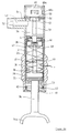
- FIG. 2A and 2B show a further preferred embodiment of an apparatus for producing an aerosol.
- the same parts are provided with the same reference numerals as in FIG. 1.
- the device has a swirling space 2 in a cylinder 2a, in which the total amount of the substance to be swirled is also accommodated.
- the volume change of the swirling space 2 is carried out by a piston 2b, which is displaceable in the cylinder 2a.
- a closure member 4 in the form of a valve is provided on the side of the swirling space opposite the piston 2b.
- the piston 2b can be displaced in the cylinder 2a by means of a piston 34 protruding from the cylinder 2a and projecting through a counter 33 to be explained further below by means of a handle 34a connected to it.
- the piston is provided with seals 35.
- a flexible sleeve 37 in the form of a latex membrane or the like is connected to its end face 36, which extends towards the swirling space 2 and which is further fixed in the area of the closure member 4 at 38 on the wall of the cylinder 2a.
- the swirling space 2 is formed within the shell 37.
- the substance is also inside the shell. This prevents substance material from adhering to the inner wall of the cylinder 2a and making the movement of the piston 2b difficult or otherwise impaired.
- an earthed coil spring 5 is arranged in the casing 37, which is fixed on the one hand on the end face 36 of the piston 2b and on the other hand in the area of the closure member 4 on the wall of the cylinder 2a.
- a plunger 39 projects into the swirling space 2 via the end face 36 of the piston 2b facing the swirling space 2, the function of which is explained below.
- the closure member 4 has a movable valve body 41 and a valve seat 42.
- the valve seat 42 is formed by a sealing ring 43 which lies tightly on the valve body 41 in the closed state.
- the valve body 41 is provided with a conical surface 45 which slides along the sealing ring 43 when the valve of the closure member 4 is closed again.
- the inside of the sealing ring is preferably not cylindrical, but rather cut-shaped or rounded.
- valve body 41 and cylinder body 47 can be formed in one piece.
- a centrally symmetrical, frustoconical recess 48 is formed, which interacts with a frustoconical front end 49 of the plunger 39 in a manner to be described.
- a mouthpiece 51 is connected to the cylinder 2a, the main direction of extension of which is perpendicular to that of the cylinder 2a extends.
- the mouthpiece has an outlet channel 53 leading to an outlet opening 52.
- a sieve plate 55 is arranged, through which the aerosol pressed out of the swirling space 2 is pressed into the channel 53 and out of the opening 52, the aerosol flow being rectified, i.e. is brought into an essentially laminar flow and the turbulence of the aerosol caused by the swirling in the swirling space 2 is largely suppressed.
- an opening 57 is preferably formed in alignment with the closure member 4, which opening can be closed by a closure plate 58, which can be closed via an axial extension 59 of the valve body 41 when it is opened and opened when the closure member 4 is closed is.
- the opening 57 opens into an intermediate space 60, which communicates with the surroundings via openings 60b in the cylinder wall 2a, which can be covered on the inside by flaps acting as check valves 60a. Thus, only air can be sucked in via the openings 60b and the opening 57, but not pushed out.
- a counter 33 is provided at the end of the cylinder 2a facing away from the mouthpiece 51.
- a resilient nose 61 is formed on the piston rod 34, which acts on a pinion 62, the axis of which is oriented perpendicular to the axis of the piston rod 34.
- On the opposite end of the pinion 62 is one Auger formed, which engages in a large ring gear 63 with internal teeth, the axis of which is aligned parallel to the axis of the piston rod 34 and optionally coincides with this.
- On the outside of the ring gear 63 there are markings which can be seen through a window.
- a toothed belt could be provided which can be actuated in the same way via a resilient extension on the piston rod 34 and has color markings which can be determined through a window. In both cases, it can thus be determined whether the intended number of operations has been carried out and the substance originally filled in the device has been used up.
- This embodiment of the device according to the invention works as follows:
- the piston 2b is pushed out of the position shown in FIG. 2A, in which it is pushed at most upwards, ie in the direction of the mouthpiece 51, so that the tip 49 of the projection 39 projects into the conical recess 48 of the plate 47, by means of the handle 34a downwards, ie pulled away from the mouthpiece 51.
- the closure member 4 is closed.
- the swirling space 2 is provided with a vacuum or a vacuum.
- the flexible coil spring 5 follows the movement of the piston 2b by pulling it apart.
- the tension-resistant and also against tension is located between the valve body 41 and the extension 39 of the piston 2b relatively inelastic thread 50 in its tensioned position.
- a further pulling down of the piston 2b up to the front side facing away from the mouthpiece 51 causes the closure member 4 to be opened by pulling down the valve body 41 (FIG. 2B).
- the opening 57 is closed by the closure plate 58.
- Charged aerosol particles then release their charges on the surface of the suitably grounded coil spring 5, which then carries them out of the swirling space 2.
- the piston 2b is again pressed onto the mouthpiece 51 by means of the handle 34a.
- the aerosol formed in the swirling space 2 is pressed out of the swirling space and through the sieve plate 55 into the channel 53 of the mouthpiece 51 until the front tip 49 of the piston neck 39 engages in the recess 48 of the plate 47 of the closure member 4 and the closure member 4 closes again.
- opening 57 is opened by lifting closure plate 58 from the opening.
- the opening 57 As long as the opening 57 is closed and thus the closure member 4 is open, the user of the device according to the invention cannot inhale. This prevents him from sucking in an undefined amount of aerosol from the swirling space 2 by inhalation. Characterized in that during the expression of aerosol from the swirling space 2 and the opening time of the closure member 4, the opening 57 is closed, a precisely defined amount of aerosol is introduced from the swirling space 2 into the mouthpiece 51, which is determined by the stroke of the piston 2b. If the opening 57 were open in this time range, air could flow in countercurrent through the opening 57 and the opened closure member 4 into the swirling space 2, so that a user could inhale an undefined amount of aerosol from the swirling space 2.
- opening 57 After opening 57 has been opened, as described, the user can inhale the aerosol located in channel 53 of mouthpiece 51. In this case, air can flow in through the opening 60b, the space 60 and the opening 57, since the flaps 60a stand out from the openings 60b during suction and expose them (again FIG. 2A). The device according to the invention is then ready to be used again.
Landscapes
- Health & Medical Sciences (AREA)
- Engineering & Computer Science (AREA)
- Bioinformatics & Cheminformatics (AREA)
- Pulmonology (AREA)
- Anesthesiology (AREA)
- Biomedical Technology (AREA)
- Heart & Thoracic Surgery (AREA)
- Hematology (AREA)
- Life Sciences & Earth Sciences (AREA)
- Animal Behavior & Ethology (AREA)
- General Health & Medical Sciences (AREA)
- Public Health (AREA)
- Veterinary Medicine (AREA)
- Containers And Packaging Bodies Having A Special Means To Remove Contents (AREA)
Applications Claiming Priority (2)
| Application Number | Priority Date | Filing Date | Title |
|---|---|---|---|
| DE19501831 | 1995-01-21 | ||
| DE1995101831 DE19501831A1 (de) | 1995-01-21 | 1995-01-21 | Vorrichtung zum Erzeugen eines Aerosols aus einer pulverförmigen Substanz |
Publications (1)
| Publication Number | Publication Date |
|---|---|
| EP0722746A1 true EP0722746A1 (fr) | 1996-07-24 |
Family
ID=7752037
Family Applications (1)
| Application Number | Title | Priority Date | Filing Date |
|---|---|---|---|
| EP95118325A Withdrawn EP0722746A1 (fr) | 1995-01-21 | 1995-11-22 | Appareil générateur d'aérosol à partir d'une substance pulvérulente |
Country Status (3)
| Country | Link |
|---|---|
| EP (1) | EP0722746A1 (fr) |
| JP (1) | JPH08252313A (fr) |
| DE (1) | DE19501831A1 (fr) |
Cited By (2)
| Publication number | Priority date | Publication date | Assignee | Title |
|---|---|---|---|---|
| WO1999012597A1 (fr) | 1997-09-10 | 1999-03-18 | Innovata Biomed Limited | Production d'un aerosol de poudre seche |
| CN110615283A (zh) * | 2019-09-04 | 2019-12-27 | 刘志海 | 一种用于玻璃生产制造的可靠性强的智能搬运装置 |
Families Citing this family (1)
| Publication number | Priority date | Publication date | Assignee | Title |
|---|---|---|---|---|
| KR101445651B1 (ko) * | 2013-01-15 | 2014-10-07 | 한국유나이티드제약 주식회사 | 분말 제재 흡입 장치 |
Citations (7)
| Publication number | Priority date | Publication date | Assignee | Title |
|---|---|---|---|---|
| CH258145A (fr) * | 1946-03-15 | 1948-11-15 | Dietsch Georges Louis Michel J | Pulvérisateur pour matière pulvérulente. |
| FR2605249A1 (fr) * | 1986-10-17 | 1988-04-22 | Gauchard Fernand | Generateur d'aerosol |
| WO1992004066A1 (fr) * | 1990-09-12 | 1992-03-19 | Hans Bisgaard | Dispositif d'inhalation |
| WO1993003033A1 (fr) | 1991-07-26 | 1993-02-18 | G. D. Searle & Co. | COMPOSES D'IMIDAZO[4,5-d] PYRIDAZINE SUBSTITUES PAR CARBONATE S'UTILISANT DANS LE TRAITEMENT DE MALADIES CARDIOVASCULAIRES |
| WO1993011817A1 (fr) * | 1991-12-16 | 1993-06-24 | The University Of Melbourne | Ameliorations relatives a l'administration de composes en aerosol |
| DE4237568C1 (de) * | 1992-11-06 | 1994-05-11 | Dieter Dipl Ing Dr Med Koehler | Verfahren und Vorrichtung zum Erzeugen eines Aerosols |
| WO1994019042A1 (fr) * | 1993-02-19 | 1994-09-01 | Bespak Plc | Appareil pour inhalation |
-
1995
- 1995-01-21 DE DE1995101831 patent/DE19501831A1/de not_active Withdrawn
- 1995-11-22 EP EP95118325A patent/EP0722746A1/fr not_active Withdrawn
-
1996
- 1996-01-19 JP JP762396A patent/JPH08252313A/ja active Pending
Patent Citations (7)
| Publication number | Priority date | Publication date | Assignee | Title |
|---|---|---|---|---|
| CH258145A (fr) * | 1946-03-15 | 1948-11-15 | Dietsch Georges Louis Michel J | Pulvérisateur pour matière pulvérulente. |
| FR2605249A1 (fr) * | 1986-10-17 | 1988-04-22 | Gauchard Fernand | Generateur d'aerosol |
| WO1992004066A1 (fr) * | 1990-09-12 | 1992-03-19 | Hans Bisgaard | Dispositif d'inhalation |
| WO1993003033A1 (fr) | 1991-07-26 | 1993-02-18 | G. D. Searle & Co. | COMPOSES D'IMIDAZO[4,5-d] PYRIDAZINE SUBSTITUES PAR CARBONATE S'UTILISANT DANS LE TRAITEMENT DE MALADIES CARDIOVASCULAIRES |
| WO1993011817A1 (fr) * | 1991-12-16 | 1993-06-24 | The University Of Melbourne | Ameliorations relatives a l'administration de composes en aerosol |
| DE4237568C1 (de) * | 1992-11-06 | 1994-05-11 | Dieter Dipl Ing Dr Med Koehler | Verfahren und Vorrichtung zum Erzeugen eines Aerosols |
| WO1994019042A1 (fr) * | 1993-02-19 | 1994-09-01 | Bespak Plc | Appareil pour inhalation |
Cited By (2)
| Publication number | Priority date | Publication date | Assignee | Title |
|---|---|---|---|---|
| WO1999012597A1 (fr) | 1997-09-10 | 1999-03-18 | Innovata Biomed Limited | Production d'un aerosol de poudre seche |
| CN110615283A (zh) * | 2019-09-04 | 2019-12-27 | 刘志海 | 一种用于玻璃生产制造的可靠性强的智能搬运装置 |
Also Published As
| Publication number | Publication date |
|---|---|
| DE19501831A1 (de) | 1996-07-25 |
| JPH08252313A (ja) | 1996-10-01 |
Similar Documents
| Publication | Publication Date | Title |
|---|---|---|
| EP0667793B1 (fr) | Procede et dispositif permettant de produire un aerosol a partir d'une substance pulverulente | |
| DE69935681T3 (de) | Vorrichtungen zur Medikamentenverabreichung | |
| DE69304333T2 (de) | Ventilanordnung | |
| DE69931034T2 (de) | Pumpe für ein dosier-inhalationsgerät | |
| EP0147755B1 (fr) | Inhalateur | |
| DE69132850T2 (de) | Wirbelkammer-Pulverinhalator | |
| EP1474195B1 (fr) | Appareil auxiliaire d'inhalation | |
| DE69319107T2 (de) | Pulverabgabevorrichtung für medizinische inhalationstherapien | |
| EP1220700A1 (fr) | Inhalateur de respiration controlée pour poudre | |
| DE60027714T3 (de) | Zerstäubungssystem mit niedriger spraykraft und retention | |
| DE69632192T2 (de) | Elektrostatisches versprühen | |
| DE60131760T2 (de) | Vorrichtung zur verabreichung von physiologisch aktiven wirkstoffen in pulverform | |
| DE69634237T2 (de) | Dosiervorrichtung für pulverförmige medikamente | |
| DE19711960A1 (de) | Medizinverabreichungsgerät für nasale Hohlräume | |
| LV10398B (en) | Inhalator | |
| DE2106794A1 (de) | Vorrichtung zum Apphzieren einer abgemessenen Pulvermenge unter Druck | |
| DE102004021789A1 (de) | Zerstäuber zum Ausbringen von Flüssigkeiten für medizinische Zwecke | |
| DE3224562A1 (de) | Dosierungsinhalator | |
| EP0553326A1 (fr) | Inhalateur | |
| EP2379142B1 (fr) | Dispositif de dosage pour la production d'un courant gazeux présentant une substance active finement répartie dans ledit courant gazeux | |
| DE69921275T2 (de) | Inhalationsgerät | |
| EP3323455B1 (fr) | Dispositif d'inhalation de brouillard de gouttelettes | |
| EP0957961A1 (fr) | Dispositif inhalateur auxiliaire | |
| DE19501831A1 (de) | Vorrichtung zum Erzeugen eines Aerosols aus einer pulverförmigen Substanz | |
| DE69515120T2 (de) | Inhalator mit optimierungskammer |
Legal Events
| Date | Code | Title | Description |
|---|---|---|---|
| PUAI | Public reference made under article 153(3) epc to a published international application that has entered the european phase |
Free format text: ORIGINAL CODE: 0009012 |
|
| AK | Designated contracting states |
Kind code of ref document: A1 Designated state(s): AT BE CH DE ES FR GB IT LI NL SE |
|
| 17P | Request for examination filed |
Effective date: 19961213 |
|
| 17Q | First examination report despatched |
Effective date: 19991230 |
|
| STAA | Information on the status of an ep patent application or granted ep patent |
Free format text: STATUS: THE APPLICATION IS DEEMED TO BE WITHDRAWN |
|
| 18D | Application deemed to be withdrawn |
Effective date: 20010418 |