EP0722794A1 - Werkzeug zum Ändern des Durchmessers, der Form oder der Konfiguration eines Rohres - Google Patents
Werkzeug zum Ändern des Durchmessers, der Form oder der Konfiguration eines Rohres Download PDFInfo
- Publication number
- EP0722794A1 EP0722794A1 EP96300276A EP96300276A EP0722794A1 EP 0722794 A1 EP0722794 A1 EP 0722794A1 EP 96300276 A EP96300276 A EP 96300276A EP 96300276 A EP96300276 A EP 96300276A EP 0722794 A1 EP0722794 A1 EP 0722794A1
- Authority
- EP
- European Patent Office
- Prior art keywords
- tool
- die
- die block
- configuration
- tool according
- Prior art date
- Legal status (The legal status is an assumption and is not a legal conclusion. Google has not performed a legal analysis and makes no representation as to the accuracy of the status listed.)
- Granted
Links
- 238000003825 pressing Methods 0.000 claims description 5
- 230000007704 transition Effects 0.000 description 3
- 238000000034 method Methods 0.000 description 2
- 230000000452 restraining effect Effects 0.000 description 2
- 230000015572 biosynthetic process Effects 0.000 description 1
- 230000000717 retained effect Effects 0.000 description 1
- 238000000926 separation method Methods 0.000 description 1
Images

Classifications
-
- B—PERFORMING OPERATIONS; TRANSPORTING
- B21—MECHANICAL METAL-WORKING WITHOUT ESSENTIALLY REMOVING MATERIAL; PUNCHING METAL
- B21D—WORKING OR PROCESSING OF SHEET METAL OR METAL TUBES, RODS OR PROFILES WITHOUT ESSENTIALLY REMOVING MATERIAL; PUNCHING METAL
- B21D41/00—Application of procedures in order to alter the diameter of tube ends
- B21D41/02—Enlarging
- B21D41/021—Enlarging by means of tube-flaring hand tools
Definitions
- This invention is concerned with improvements in and relating to tools, such as those used for flaring and particularly, though not exclusively, those used for expanding the ends of brake pipe fittings.
- a tool for use in altering the diameter, shape or configuration of an article including a die for controlling the shape to which the article deforms and the tool being adapted to cooperate with means for applying pressure to deform the article, wherein the die is provided in a die block which is removable from the tool.
- the die can readily be replaced whether for repair or to insert a die block containing a die of different size.
- the tool may be provided with two or more dies, preferably one die is provided at one end of a passage provided in the tool and another die is provided at the other end of the passage.
- the tool has a longer life as two dies will last longer than one before becoming unusable due to damage.
- a tool for use in altering the diameter, shape or configuration of an article including means for controlling the deformation of the article and the tool being adapted to cooperate with means for applying pressure to deform the article, wherein the deformation controlling means comprises one or more passages through the tool, one or more of the passages being provided with a die portion at one end and a further die portion at the other end.
- the dies may be provided within a die block which is removable from the tool. In this way replacement of the die is made easier and cheaper as complete replacement of the tool is not required.
- One or more of the dies provided may be of different sizes and/or be of different configuration to one or more of the other dies. In this way a tool is provided which is far more versatile as different sizes of flaring or different types of flaring can be effected without the need to change tool or die block.
- the tool may include two body components having a closed and released state, the components cooperating in the closed state to retain the releasable die block in the tool, and in the released state permitting the removal of the die block.
- the body components are pivotally connected so as to provide an easily and accurately reproducable transition from the closed to released state and vice versa.
- pivotal connection is provided at an end of the tool, ideally at the end opposed to a handle portion used for supporting the tool, for ease of handling.
- the die block is preferably accommodated in an aperture in the tool.
- the aperture is defined in part by one of the tool body components and in part by another. In this way easy access can be obtained in the released state.
- the body components are held in the closed state by retaining means which engage with the body components. This ensures the die block is firmly held in place during flaring and no undesirable separation of the body components occurs.
- the retaining means comprise a threaded member.
- the threaded member may be pivotally attached to one of the body components and cooperate with a notch on the other. Additional restraining force may be applied by tightening an additional member on the threaded member so as to abut with the second body component.
- a kit comprising a tool according to the first aspect of the invention and/or a tool according to the second aspect, with a removable die block, wherein the kit includes one or more additional die blocks.
- the kit includes die blocks which provide a range of sizes of dies and/or dies for a range of flaring applications.
- the kit thus provided represents a versatile and readily-to-hand set of apparatus.
- a die block having one or more through passages, one or more of the passages being provided with a die at one end and a further die at the other end.
- the dies are of different sizes and/or configurations.
- Sets of two or more such die blocks may be provided.
- a tool for use in altering the diameter, shape or configuration of a tubular article including a die for controlling the deformation of the article and the tool being adapted to cooperate with means for applying pressure to deform the article, wherein the pressure is applied by hydraulically activated means.
- the tool is hand held, easing its use and location of use.
- the tool may be provided with a clamping member which cooperates with the pressure applying means.
- the pressure applying means may cooperate with the clamping member by means of a threaded engagement.
- the clamping member may be releasable from the tool.
- the clamping member may engage the tool by means of threaded connectors.
- notches in the clamping member may cooperate with ridges on the tool, or vice versa, to position the clamping member relative to the tool.
- the tool 1 comprises a handle member 2 and housing member 3 pivotally mounted relative to each other at their respective ends 4, 5 by a pin 6.
- Each member 2, 3 has a channel 7, 8 extending over their full width, which channels oppose each other in the closed position, when surface 9 abuts surface 10.
- the channels 7, 8 accommodate a removable die block 11 (shown in Figure 3). In the closed position the die block 11 is restrained within the channels 7, 8.
- the handle member 2 also has a hand-held portion 12 by means of which the operator controls and positions the tool.
- a threaded member 13 is pivotally mounted between two projections 14 from the handle member 2 base by means of a pin 15. With the housing member 3 in the closed position the threaded member 13 can be swung so as to pass between opposing projections 16 on the housing member 3. The nut 17 can then be screwed down until it abuts surface 18 on housing member 3. The members 2, 3 are thus retained in the closed formation.
- the die block 11 comprises a rectangular block with a central axially aligned passage 19 having enlarged end portions 20, 21.
- the transition surface 22 between the passage 19 and enlarged portion 20 onto the right end is radial, so providing for DIN type flaring.
- the left end provides an axially inclined radiating surface 23, so providing for SAE type flaring.
- the tool 1 is opened and the die block 11 having the desired size passage 19 is inserted in the channel 7, 8.
- the die block 11 is inserted so that the desired transition surface configuration is on the desired side of the tool 1.
- the tool 1 is then closed and the handle and die housing members 2, 3 respectively are restrained relative to one another by the threaded member 13 as previously discussed.
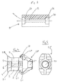
- FIG. 4 This provides for a tool assembly having a configuration as seen end-on in Figure 4.
- Each of the housing and handle members 2, 3 are provided with a rib 28 raised relative to the member.
- the rib 20 runs along each side of each member.
- An hydraulic mounting member 25 can then be slid over the end of the tool 1 and run along the ribs 28.
- the hydraulic mounting member is provided with notches 26 which cooperate with the ribs to resist direct movement away from the members 2, 3.
- the hydraulic mounting member 25 is provided with a threaded aperture 27 into which the hydraulically operated stamp can be screwed.
- the stamp is consequently held in position relative to the members 2, 3 during the flaring operation.
- Flaring is effected by applying hydraulic pressure to the stamp so forcing the cone into the pipe and expanding it to the die configuration.
- the flared pipe is extracted by removing the hydraulic stamp, hydraulic mounting member, threaded member and opening the members 2, 3 in the reverse of the aforementioned procedure.
Landscapes
- Engineering & Computer Science (AREA)
- Mechanical Engineering (AREA)
- Shaping Metal By Deep-Drawing, Or The Like (AREA)
- Prostheses (AREA)
- Moulds For Moulding Plastics Or The Like (AREA)
Applications Claiming Priority (2)
| Application Number | Priority Date | Filing Date | Title |
|---|---|---|---|
| GB9500862 | 1995-01-17 | ||
| GBGB9500862.9A GB9500862D0 (en) | 1995-01-17 | 1995-01-17 | Improvements in and relating to tools |
Publications (2)
| Publication Number | Publication Date |
|---|---|
| EP0722794A1 true EP0722794A1 (de) | 1996-07-24 |
| EP0722794B1 EP0722794B1 (de) | 2001-03-14 |
Family
ID=10768132
Family Applications (1)
| Application Number | Title | Priority Date | Filing Date |
|---|---|---|---|
| EP19960300276 Expired - Lifetime EP0722794B1 (de) | 1995-01-17 | 1996-01-15 | Werkzeug zum Ändern des Durchmessers, der Form oder der Konfiguration eines Rohres |
Country Status (4)
| Country | Link |
|---|---|
| EP (1) | EP0722794B1 (de) |
| DE (1) | DE69612023T2 (de) |
| ES (1) | ES2154787T3 (de) |
| GB (1) | GB9500862D0 (de) |
Cited By (3)
| Publication number | Priority date | Publication date | Assignee | Title |
|---|---|---|---|---|
| US6619099B2 (en) | 2000-10-16 | 2003-09-16 | Mastercool, Inc. | Hydraulically powered flaring hand tool |
| CN103567310A (zh) * | 2012-07-26 | 2014-02-12 | 珠海格力电器股份有限公司 | 一种管件扩喇叭口夹模 |
| US10226810B2 (en) | 2016-06-07 | 2019-03-12 | Uniweld Products, Inc. | Expanding tool and method |
Citations (5)
| Publication number | Priority date | Publication date | Assignee | Title |
|---|---|---|---|---|
| US2241091A (en) * | 1939-06-08 | 1941-05-06 | Hood Josa Allen | Tube-end expander |
| FR1028057A (fr) * | 1950-09-28 | 1953-05-19 | Thomas Et Bordenave P | Dispositif pour le façonnage des tuyaux |
| US2737225A (en) * | 1951-09-20 | 1956-03-06 | Mathew S Jasinski | Pipe flaring device |
| US3913364A (en) * | 1974-07-11 | 1975-10-21 | Imp Eastman Corp | Flaring tool |
| EP0501928A1 (de) * | 1991-02-22 | 1992-09-02 | REFI AUTOMAZIONI OLEODINAMICHE S.r.l. | Rohraufweitungswerkzeug |
-
1995
- 1995-01-17 GB GBGB9500862.9A patent/GB9500862D0/en active Pending
-
1996
- 1996-01-15 EP EP19960300276 patent/EP0722794B1/de not_active Expired - Lifetime
- 1996-01-15 DE DE1996612023 patent/DE69612023T2/de not_active Expired - Lifetime
- 1996-01-15 ES ES96300276T patent/ES2154787T3/es not_active Expired - Lifetime
Patent Citations (5)
| Publication number | Priority date | Publication date | Assignee | Title |
|---|---|---|---|---|
| US2241091A (en) * | 1939-06-08 | 1941-05-06 | Hood Josa Allen | Tube-end expander |
| FR1028057A (fr) * | 1950-09-28 | 1953-05-19 | Thomas Et Bordenave P | Dispositif pour le façonnage des tuyaux |
| US2737225A (en) * | 1951-09-20 | 1956-03-06 | Mathew S Jasinski | Pipe flaring device |
| US3913364A (en) * | 1974-07-11 | 1975-10-21 | Imp Eastman Corp | Flaring tool |
| EP0501928A1 (de) * | 1991-02-22 | 1992-09-02 | REFI AUTOMAZIONI OLEODINAMICHE S.r.l. | Rohraufweitungswerkzeug |
Cited By (4)
| Publication number | Priority date | Publication date | Assignee | Title |
|---|---|---|---|---|
| US6619099B2 (en) | 2000-10-16 | 2003-09-16 | Mastercool, Inc. | Hydraulically powered flaring hand tool |
| CN103567310A (zh) * | 2012-07-26 | 2014-02-12 | 珠海格力电器股份有限公司 | 一种管件扩喇叭口夹模 |
| US10226810B2 (en) | 2016-06-07 | 2019-03-12 | Uniweld Products, Inc. | Expanding tool and method |
| US11389856B2 (en) | 2016-06-07 | 2022-07-19 | Uniweld Products, Inc. | Expanding tool and method |
Also Published As
| Publication number | Publication date |
|---|---|
| DE69612023T2 (de) | 2001-07-19 |
| EP0722794B1 (de) | 2001-03-14 |
| GB9500862D0 (en) | 1995-03-08 |
| ES2154787T3 (es) | 2001-04-16 |
| DE69612023D1 (de) | 2001-04-19 |
Similar Documents
| Publication | Publication Date | Title |
|---|---|---|
| US5105648A (en) | Molded lightweight handtool with structural insert | |
| US4528735A (en) | Tire tool | |
| US4426758A (en) | Seal puller | |
| US6195863B1 (en) | Disc brake piston installation tool | |
| KR930006782B1 (ko) | 튜브 풀링 장치 | |
| US6244580B1 (en) | Machining vise | |
| US4982631A (en) | Mechanic's tubing plug | |
| EP0565580A1 (de) | Verfahren zum herausziehen von lagern, eine lagerzieh-vorrichtung und deren gebrauch. | |
| CA1287793C (en) | Stamping system | |
| DE4238700C2 (de) | Vorrichtung zur Befestigung von Verbindungselementen an Rohrleitungen | |
| US20090031778A1 (en) | Multi-application crimping or pressing tool | |
| CN101222987A (zh) | 弯管器和弯曲方法 | |
| CA2346950C (en) | Punch guide assembly | |
| EP0722794A1 (de) | Werkzeug zum Ändern des Durchmessers, der Form oder der Konfiguration eines Rohres | |
| US7305749B2 (en) | Wire terminal crimper | |
| US20060144116A1 (en) | Pipe flaring tool | |
| US4515006A (en) | Hose coupling crimper and method of crimping | |
| EP1743741B1 (de) | Schraubstock für Rohre | |
| CA2642470A1 (en) | Crimping apparatus with a support structure including first and second portions | |
| US6019357A (en) | Uniforce hydraulic clamp | |
| US7526940B2 (en) | Die element changing devices | |
| US3626450A (en) | Portable swaging tool | |
| US6385846B1 (en) | Method for removing an oil seal | |
| US6450002B1 (en) | Compact apparatus for grooving a tube and method for grooving a tube | |
| JPH11508825A (ja) | クリンパ組立体 |
Legal Events
| Date | Code | Title | Description |
|---|---|---|---|
| PUAI | Public reference made under article 153(3) epc to a published international application that has entered the european phase |
Free format text: ORIGINAL CODE: 0009012 |
|
| AK | Designated contracting states |
Kind code of ref document: A1 Designated state(s): DE ES FR GB IT |
|
| 17P | Request for examination filed |
Effective date: 19970117 |
|
| 17Q | First examination report despatched |
Effective date: 19970924 |
|
| GRAG | Despatch of communication of intention to grant |
Free format text: ORIGINAL CODE: EPIDOS AGRA |
|
| GRAG | Despatch of communication of intention to grant |
Free format text: ORIGINAL CODE: EPIDOS AGRA |
|
| GRAG | Despatch of communication of intention to grant |
Free format text: ORIGINAL CODE: EPIDOS AGRA |
|
| GRAH | Despatch of communication of intention to grant a patent |
Free format text: ORIGINAL CODE: EPIDOS IGRA |
|
| GRAH | Despatch of communication of intention to grant a patent |
Free format text: ORIGINAL CODE: EPIDOS IGRA |
|
| GRAA | (expected) grant |
Free format text: ORIGINAL CODE: 0009210 |
|
| AK | Designated contracting states |
Kind code of ref document: B1 Designated state(s): DE ES FR GB IT |
|
| REG | Reference to a national code |
Ref country code: ES Ref legal event code: FG2A Ref document number: 2154787 Country of ref document: ES Kind code of ref document: T3 |
|
| REF | Corresponds to: |
Ref document number: 69612023 Country of ref document: DE Date of ref document: 20010419 |
|
| ITF | It: translation for a ep patent filed | ||
| ET | Fr: translation filed | ||
| RAP2 | Party data changed (patent owner data changed or rights of a patent transferred) |
Owner name: FACOM UK LIMITED |
|
| REG | Reference to a national code |
Ref country code: GB Ref legal event code: IF02 |
|
| PLBE | No opposition filed within time limit |
Free format text: ORIGINAL CODE: 0009261 |
|
| STAA | Information on the status of an ep patent application or granted ep patent |
Free format text: STATUS: NO OPPOSITION FILED WITHIN TIME LIMIT |
|
| REG | Reference to a national code |
Ref country code: FR Ref legal event code: TP |
|
| 26N | No opposition filed | ||
| REG | Reference to a national code |
Ref country code: GB Ref legal event code: 732E |
|
| PG25 | Lapsed in a contracting state [announced via postgrant information from national office to epo] |
Ref country code: IT Free format text: LAPSE BECAUSE OF NON-PAYMENT OF DUE FEES;WARNING: LAPSES OF ITALIAN PATENTS WITH EFFECTIVE DATE BEFORE 2007 MAY HAVE OCCURRED AT ANY TIME BEFORE 2007. THE CORRECT EFFECTIVE DATE MAY BE DIFFERENT FROM THE ONE RECORDED. Effective date: 20050115 |
|
| PGFP | Annual fee paid to national office [announced via postgrant information from national office to epo] |
Ref country code: ES Payment date: 20061221 Year of fee payment: 12 |
|
| REG | Reference to a national code |
Ref country code: GB Ref legal event code: 732E |
|
| REG | Reference to a national code |
Ref country code: FR Ref legal event code: TP Ref country code: FR Ref legal event code: CD Ref country code: FR Ref legal event code: CA |
|
| REG | Reference to a national code |
Ref country code: ES Ref legal event code: FD2A Effective date: 20080116 |
|
| PG25 | Lapsed in a contracting state [announced via postgrant information from national office to epo] |
Ref country code: ES Free format text: LAPSE BECAUSE OF NON-PAYMENT OF DUE FEES Effective date: 20080116 |
|
| PGFP | Annual fee paid to national office [announced via postgrant information from national office to epo] |
Ref country code: IT Payment date: 20070504 Year of fee payment: 12 |
|
| PGRI | Patent reinstated in contracting state [announced from national office to epo] |
Ref country code: IT Effective date: 20091201 |
|
| PGFP | Annual fee paid to national office [announced via postgrant information from national office to epo] |
Ref country code: DE Payment date: 20100128 Year of fee payment: 15 |
|
| REG | Reference to a national code |
Ref country code: DE Ref legal event code: R119 Ref document number: 69612023 Country of ref document: DE Effective date: 20110802 |
|
| PGFP | Annual fee paid to national office [announced via postgrant information from national office to epo] |
Ref country code: FR Payment date: 20130225 Year of fee payment: 18 |
|
| PG25 | Lapsed in a contracting state [announced via postgrant information from national office to epo] |
Ref country code: DE Free format text: LAPSE BECAUSE OF NON-PAYMENT OF DUE FEES Effective date: 20110802 |
|
| PGRI | Patent reinstated in contracting state [announced from national office to epo] |
Ref country code: IT Effective date: 20091201 |
|
| REG | Reference to a national code |
Ref country code: FR Ref legal event code: ST Effective date: 20140930 |
|
| PG25 | Lapsed in a contracting state [announced via postgrant information from national office to epo] |
Ref country code: FR Free format text: LAPSE BECAUSE OF NON-PAYMENT OF DUE FEES Effective date: 20140131 |
|
| PGFP | Annual fee paid to national office [announced via postgrant information from national office to epo] |
Ref country code: GB Payment date: 20150127 Year of fee payment: 20 |
|
| REG | Reference to a national code |
Ref country code: GB Ref legal event code: PE20 Expiry date: 20160114 |
|
| PG25 | Lapsed in a contracting state [announced via postgrant information from national office to epo] |
Ref country code: GB Free format text: LAPSE BECAUSE OF EXPIRATION OF PROTECTION Effective date: 20160114 |