EP0722848B1 - Roulette pivotante à blocage directionnel protégé - Google Patents
Roulette pivotante à blocage directionnel protégé Download PDFInfo
- Publication number
- EP0722848B1 EP0722848B1 EP95402941A EP95402941A EP0722848B1 EP 0722848 B1 EP0722848 B1 EP 0722848B1 EP 95402941 A EP95402941 A EP 95402941A EP 95402941 A EP95402941 A EP 95402941A EP 0722848 B1 EP0722848 B1 EP 0722848B1
- Authority
- EP
- European Patent Office
- Prior art keywords
- roller
- wheel
- fact
- skirt
- axis
- Prior art date
- Legal status (The legal status is an assumption and is not a legal conclusion. Google has not performed a legal analysis and makes no representation as to the accuracy of the status listed.)
- Expired - Lifetime
Links
Images


Classifications
-
- B—PERFORMING OPERATIONS; TRANSPORTING
- B60—VEHICLES IN GENERAL
- B60B—VEHICLE WHEELS; CASTORS; AXLES FOR WHEELS OR CASTORS; INCREASING WHEEL ADHESION
- B60B33/00—Castors in general ; Anti-clogging castors
- B60B33/02—Castors in general ; Anti-clogging castors with disengageable swivel action, i.e. comprising a swivel locking mechanism
- B60B33/025—Castors in general ; Anti-clogging castors with disengageable swivel action, i.e. comprising a swivel locking mechanism by using form-fit, e.g. front teeth
-
- B—PERFORMING OPERATIONS; TRANSPORTING
- B60—VEHICLES IN GENERAL
- B60B—VEHICLE WHEELS; CASTORS; AXLES FOR WHEELS OR CASTORS; INCREASING WHEEL ADHESION
- B60B33/00—Castors in general ; Anti-clogging castors
- B60B33/006—Castors in general ; Anti-clogging castors characterised by details of the swivel mechanism
- B60B33/0065—Castors in general ; Anti-clogging castors characterised by details of the swivel mechanism characterised by details of the swivel axis
- B60B33/0068—Castors in general ; Anti-clogging castors characterised by details of the swivel mechanism characterised by details of the swivel axis the swivel axis being vertical
-
- B—PERFORMING OPERATIONS; TRANSPORTING
- B60—VEHICLES IN GENERAL
- B60B—VEHICLE WHEELS; CASTORS; AXLES FOR WHEELS OR CASTORS; INCREASING WHEEL ADHESION
- B60B2200/00—Type of product being used or applied
- B60B2200/20—Furniture or medical appliances
- B60B2200/22—Chairs
-
- B—PERFORMING OPERATIONS; TRANSPORTING
- B60—VEHICLES IN GENERAL
- B60B—VEHICLE WHEELS; CASTORS; AXLES FOR WHEELS OR CASTORS; INCREASING WHEEL ADHESION
- B60B33/00—Castors in general ; Anti-clogging castors
- B60B33/0036—Castors in general ; Anti-clogging castors characterised by type of wheels
- B60B33/0039—Single wheels
-
- B—PERFORMING OPERATIONS; TRANSPORTING
- B60—VEHICLES IN GENERAL
- B60B—VEHICLE WHEELS; CASTORS; AXLES FOR WHEELS OR CASTORS; INCREASING WHEEL ADHESION
- B60B33/00—Castors in general ; Anti-clogging castors
- B60B33/0047—Castors in general ; Anti-clogging castors characterised by details of the rolling axle
- B60B33/0049—Castors in general ; Anti-clogging castors characterised by details of the rolling axle the rolling axle being horizontal
-
- B—PERFORMING OPERATIONS; TRANSPORTING
- B60—VEHICLES IN GENERAL
- B60B—VEHICLE WHEELS; CASTORS; AXLES FOR WHEELS OR CASTORS; INCREASING WHEEL ADHESION
- B60B33/00—Castors in general ; Anti-clogging castors
- B60B33/0047—Castors in general ; Anti-clogging castors characterised by details of the rolling axle
- B60B33/0057—Castors in general ; Anti-clogging castors characterised by details of the rolling axle the rolling axle being offset from swivel axis
Definitions
- the present invention relates to a swivel castor with locking mechanism directional comprising a wheel pivotable about an axis of vertical pivoting substantially orthogonal to the axis of rotation of the wheel and offset from the latter, a support bearing having at least one inverted annular bowl which, by its central part, is fixed on the lower end of said pivot axis, a yoke of support having at least one side cheek whose lower end carries said wheel and also having a skirt arranged around the lower end of the pivot axis, said skirt being connected at the upper end of said cheek and cooperating with the organs of rolling of said bearing, a spring leaf arranged in space between the support bearing and the tread of the wheel and articulated by its middle part on the yoke, said leaf spring having a first end resting on the skirt and a second end with a locking bolt in support sliding on the lower edge of the bowl and likely to engage in a depression provided on said lower edge.
- the object of the present invention is to overcome these drawbacks.
- the invention achieves its object by the fact that the blocking lock has a roller mounted for free rotation around a roller axis, by the causes said roller pin to be fixed to a curved end of the blade spring and by the fact that means are provided for protecting said roller against side impact.
- the roller is arranged in a plane substantially parallel to the arched end of the spring leaf.
- the space under the pebble is completely free, which eliminates the dirt encrustation in this area.
- the camber of the end of the spring blade allows good contact with the roller blocking with the lower edge of the bowl.
- the protection of the locking roller can be ensured by a cover fixed to the free end of the roller axis, either by riveting, welding, snap-in. It can also be secured by two sheet metal flaps cut in the yoke and extending laterally on each side of the pebble.
- the protection of the locking roller is ensured by a bracket fixed to the yoke by welding, snap-fastening, or riveting.
- the stirrup is fixed on the ends of a mounted shaft on the yoke parallel to the axis of rotation of the wheel and on which is articulated the middle part of the spring leaf.
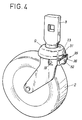
- Roulette 1 shown in the drawings has a wheel 2 which is likely to be able to pivot around a vertical axis of pivot 3 substantially orthogonal to the horizontal axis of rotation 4 of the wheel 2.
- the ends of the axis of rotation 4 are carried by at minus one side cheek, and preferably two side cheeks 5, of a yoke 6, the upper part of which is in the form of a skirt 7 mounted via a support bearing 8 on the end lower of the vertical pivot axis 3.
- pivot axis is meant any rod or plate intended to fix the caster 1 on a trolley or other mobile platform not shown in the drawing.
- the support bearing 8 includes a first annular bowl 9 and a second bowl annular 10 fixed like the first, rigidly on the end bottom of the pivot axis 3.
- the two bowls 9 and 10 are open down.
- the first bowl 9 is disposed above the second bowl 10 and has an outer bell-shaped skirt 9a, to which is connected to the upper part, an annular bottom turned down 9b which in the interior opening area rests on the annular bottom 10a of the lower bowl 10.
- the two bowls 9, 10 are fixed on the pivot axis 3 and are enclosed by their inner edges between two annular shoulders 3a, 3b of the axis vertical 3.
- this lower bowl 10 has an annular rim 10b which, by its upper face, serves as raceway to a first set of ball bearings or similar bodies 11 on which the skirt 7 of the yoke is supported support 6.
- the upper bowl 9 delimits a track of groove-shaped bearing 12 in which is housed a second series of rolling balls 13 resting on the upper face of the skirt 7.
- the upper bowl 9 surrounds and covers the skirt 7 and the bowl lower 10.
- the swivel caster 1 also includes means for blocking 16 of the yoke 6 at least in a direction predetermined by relative to the pivot axis 3.
- the locking means 16 comprise a spring leaf 17 in the form generally flat and arranged in the space between the bearing support 8 and the tread 2a of the wheel 2.
- the spring leaf 17 is articulated by its middle part on the yoke 6 by means of a hinge axis 18 substantially parallel to the axis of rotation 4 of the wheel 2.
- a first end 19 of the spring leaf 17 is in abutment on the lower edge of the skirt 7 while its other end 20 has a blocking latch 21 which is held in abutment on the edge lower free 22 of the upper bowl 9.
- This edge 22 comprises at minus a depression 23 adapted to the shape of the locking bolt 21 and produced in the form of a notch having lateral ramps 24 inclined at 45 °, to allow the wheel pivot to be released 2 by exerting a torque on the yoke 6 or the axis of pivot 3.
- the skirt 7 comprises, in the vicinity of the locking bolt 21, a notch 25 of rectangular shape intended to guide the end 20 of the spring leaf 17.
- the spring leaf 17 is mounted on the hinge pin 18 at by means of a prismatic cam 26 the plates of which comprise at least a lug 30 cooperating with a hole in the spring leaf 17.
- the locking bolt 21 is constituted a roller 31 mounted for free rotation on a roller axis 32 fixed on the arched end 20 of the spring leaf.
- the roller 31 has a counterbore intended to receive the head of the roller axis 32, thus avoiding any protruding part on the rear face 33 of the roller 31.
- a shoulder 34 on the front face of the roller 31, located opposite the end 20 of the blade to spring eliminates the contact of the roller 31 with the yoke 6.
- the roller 31 is disposed in a substantially vertical plane parallel to the end 20 of the spring leaf. Thus the periphery of the roller 31 is in precise contact with the lower edge 22 of the bowl 9.
- the reference 35 designates a protection device arranged opposite the rear face 33 of the roller 31 and intended to protect the roller 31 against side impacts.
- the protection device 35 consists of a cover 36 fixed on the axis of roller 32, the latter in this case extending rearward.
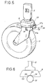
- the protection device 35 consists of two sheet metal flaps 37a, 37b cut from yoke 6 and extending rearward on each side side of the roller 31.
- the protection device 35 is provided by a stirrup 38 whose ends 39 are fixed on the ends of the hinge pin 18 of the leaf spring 17.
- the yoke 6 has in the vicinity of these ends of the axis two stampings in which the ends 39 of the stirrup 38 are completely immobilized with respect to the yoke 6.
- the stirrup 38 advantageously comprises a reinforcing rod 40 participating in its rigidity.
- the protective device 35 like the other components of the frame participating in the pivoting, receives a treatment specific thermochemical, which increases its mechanical resistance and ensures its resistance to corrosion.
- Thermochemical treatment is preferably performed according to the method described in the document EP-A-0 077 627.
Landscapes
- Engineering & Computer Science (AREA)
- Mechanical Engineering (AREA)
- Handcart (AREA)
- Surgical Instruments (AREA)
- Joints Allowing Movement (AREA)
- Pivots And Pivotal Connections (AREA)
- Legs For Furniture In General (AREA)
- Vehicle Cleaning, Maintenance, Repair, Refitting, And Outriggers (AREA)
- Rollers For Roller Conveyors For Transfer (AREA)
- Vehicle Body Suspensions (AREA)
Description
Claims (6)
- Roulette pivotante à blocage directionnel comportant une roue (2) pivotable autour d'un axe de pivotement (3) vertical sensiblement orthogonal à l'axe de rotation (4) de la roue (2) et décalé par rapport à ce dernier, un palier de support (8) présentant au moins une cuvette annulaire (9) renversée qui, par sa partie centrale, est fixée sur l'extrémité inférieure dudit axe de pivotement (3), une chape de support (6) présentant au moins une joue latérale (5) dont l'extrémité inférieure porte ladite roue (2) et présentant également une jupe (7) disposée autour de l'extrémité inférieure de l'axe de pivotement (3), ladite jupe (7) étant raccordée à l'extrémité supérieure de ladite joue (5) et coopérant avec les organes de roulement (11, 13) dudit palier (8), une lame à ressort (17) disposée dans l'espace compris entre le palier de support (8) et la bande de roulement (2a) de la roue (2) et articulée par sa partie médiane sur la chape (6), ladite lame à ressort (17) comportant une première extrémité (19) en appui sur la jupe (7) et une deuxième extrémité (20) équipée d'un verrou de blocage (21) en appui coulissant sur le bord inférieur (22) de la cuvette (9) et susceptible de s'engager dans une dépression (23) prévue sur ledit bord inférieur (22), caractérisée par le fait que le verrou de blocage (21) comporte un galet (31) monté à rotation libre autour d'un axe de galet (32), par le fait que ledit axe de galet (32) est fixé sur une extrémité cambrée (20) de la lame à ressort (17) et par le fait qu'il est prévu les moyens de protection (35) dudit galet (31) contre les chocs latéraux.
- Roulette selon la revendication 1, caractérisée par le fait que les moyens de protection (35) comportent un cache (36) fixé à l'extrémité libre de l'axe de galet (32).
- Roulette selon la revendication 1, caractérisée par le fait que les moyens de protection (35) comportent deux rabats de tôle (37a, 37b) découpés dans la chape (6) et s'étendant latéralement de chaque côté du galet (31).
- Roulette selon la revendication 1, caractérisée par le fait que les moyens de protection (35) comportent un étrier (38) fixé sur la chape (6).
- Roulette selon la revendication 4, caractérisée par le fait que la lame à ressort (17) est articulée sur un arbre (18) monté sur la chape (6) et parallèle à l'axe de rotation (4) de la roue (2), et par le fait que l'étrier (38) est fixé sur les extrémités dudit arbre (18).
- Roulette selon la revendication 5, caractérisée par le fait que la chape (6) comporte au voisinage des extrémités de l'arbre (18) deux estampages destinés à recevoir les extrémités (39) de l'étrier (38).
Applications Claiming Priority (2)
| Application Number | Priority Date | Filing Date | Title |
|---|---|---|---|
| FR9500631 | 1995-01-20 | ||
| FR9500631A FR2729614B1 (fr) | 1995-01-20 | 1995-01-20 | Roulette pivotante a blocage directionnel protege |
Publications (2)
| Publication Number | Publication Date |
|---|---|
| EP0722848A1 EP0722848A1 (fr) | 1996-07-24 |
| EP0722848B1 true EP0722848B1 (fr) | 1999-03-03 |
Family
ID=9475328
Family Applications (1)
| Application Number | Title | Priority Date | Filing Date |
|---|---|---|---|
| EP95402941A Expired - Lifetime EP0722848B1 (fr) | 1995-01-20 | 1995-12-26 | Roulette pivotante à blocage directionnel protégé |
Country Status (5)
| Country | Link |
|---|---|
| EP (1) | EP0722848B1 (fr) |
| AT (1) | ATE177057T1 (fr) |
| DE (1) | DE69508054T2 (fr) |
| ES (1) | ES2128684T3 (fr) |
| FR (1) | FR2729614B1 (fr) |
Families Citing this family (1)
| Publication number | Priority date | Publication date | Assignee | Title |
|---|---|---|---|---|
| WO2005044713A2 (fr) * | 2003-11-04 | 2005-05-19 | Burton Stewart S | Dispositif et procede de levage |
Family Cites Families (6)
| Publication number | Priority date | Publication date | Assignee | Title |
|---|---|---|---|---|
| US4494272A (en) * | 1981-07-21 | 1985-01-22 | Natsuo Morita | Reversible caster device having brake mechanism |
| US4496401A (en) | 1981-10-15 | 1985-01-29 | Lucas Industries | Corrosion resistant steel components and method of manufacture thereof |
| GB2200042B (en) * | 1987-01-21 | 1991-05-29 | British Castors Ltd | Castor |
| US4911269A (en) * | 1988-12-02 | 1990-03-27 | Shepherd Products Limited | Twin wheel caster with integral brake assembly |
| FR2703300B1 (fr) * | 1993-03-30 | 1995-06-30 | Guitel Etienne Mobilor | Roulette pivotante a blocage directionnel. |
| DE9317256U1 (de) * | 1993-11-11 | 1994-01-20 | Lothar Laflör GmbH & Co, 42553 Velbert | Lenkrolle |
-
1995
- 1995-01-20 FR FR9500631A patent/FR2729614B1/fr not_active Expired - Fee Related
- 1995-12-26 EP EP95402941A patent/EP0722848B1/fr not_active Expired - Lifetime
- 1995-12-26 ES ES95402941T patent/ES2128684T3/es not_active Expired - Lifetime
- 1995-12-26 DE DE69508054T patent/DE69508054T2/de not_active Expired - Fee Related
- 1995-12-26 AT AT95402941T patent/ATE177057T1/de not_active IP Right Cessation
Also Published As
| Publication number | Publication date |
|---|---|
| EP0722848A1 (fr) | 1996-07-24 |
| ES2128684T3 (es) | 1999-05-16 |
| FR2729614B1 (fr) | 1997-04-18 |
| DE69508054T2 (de) | 1999-08-05 |
| ATE177057T1 (de) | 1999-03-15 |
| FR2729614A1 (fr) | 1996-07-26 |
| DE69508054D1 (de) | 1999-04-08 |
Similar Documents
| Publication | Publication Date | Title |
|---|---|---|
| EP0618089B1 (fr) | Roulette pivotante à blocage directionnel | |
| FR2808747A1 (fr) | Siege amovible pour vehicule automobile | |
| EP0340260B1 (fr) | Patin a roulettes comportant au moins deux roulettes alignees le long d'un plan median | |
| EP1747138B1 (fr) | Plateforme a roulettes attelable a une poussette | |
| EP0760295B1 (fr) | Chariot comprenant un bâti monté sur dispositifs à roulette pivotante, et dispositif à roulette pivotante en particulier pour un tel chariot | |
| EP2482943B1 (fr) | Chaussure polyvalente pour la marche et le roulage, comportant des roulettes intégrées à la semelle, dépliables latéralement. | |
| FR2766322A1 (fr) | Equipement frontal pourvu de roues d'appui, destine a une machine agricole | |
| EP0424234B1 (fr) | Roulette pivotante pour chariot | |
| FR2785585A1 (fr) | Dispositif a energie electrique monte sur un essieu | |
| EP0722848B1 (fr) | Roulette pivotante à blocage directionnel protégé | |
| FR2503051A1 (fr) | Moyeu pour vehicule a deux roues | |
| FR2784559A3 (fr) | Trotteur pour bebe equipe d'un dispositif de freinage de securite | |
| EP0424233B1 (fr) | Dispositif à roulette pivotante | |
| EP0296939B1 (fr) | Accoudoir central avant à deux positions stables d'un véhicule automobile | |
| EP0722849B1 (fr) | Roulette pivotante à blocage directionnel à couple réglable | |
| FR2744186A1 (fr) | Dispositif de palier a bascule destine a porter l'une des extremites d'une barre enrouleuse | |
| EP0569292B1 (fr) | Roulette pivotante | |
| EP0330556A1 (fr) | Présentoir rotatif pour véhicule automobile | |
| FR2688741A1 (fr) | Roulette pivotante pour chariot. | |
| EP0063081B1 (fr) | Dispositif de montage de siège coulissant et règlable pour véhicule automobile | |
| WO2025125758A1 (fr) | Casque de protection muni d'une mentonniere amovible | |
| FR2646315A1 (fr) | Machine agricole comportant au moins un rotor muni d'outils et s'appuyant sur le sol durant le travail | |
| EP0153236A1 (fr) | Remorque pour la mise hors d'eau et le transport des bateaux, notamment des bateaux de plaisance | |
| EP1029710A1 (fr) | Chariot comprenant un bâti monté sur dispositifs à roulette pivotante, et dispositif à roulette pivotante en particulier pour un tel chariot | |
| FR2749897A1 (fr) | Moyeu roue libre pour une roue de cycle |
Legal Events
| Date | Code | Title | Description |
|---|---|---|---|
| PUAI | Public reference made under article 153(3) epc to a published international application that has entered the european phase |
Free format text: ORIGINAL CODE: 0009012 |
|
| AK | Designated contracting states |
Kind code of ref document: A1 Designated state(s): AT BE CH DE ES GB IT LI LU NL PT SE |
|
| 17P | Request for examination filed |
Effective date: 19970110 |
|
| GRAG | Despatch of communication of intention to grant |
Free format text: ORIGINAL CODE: EPIDOS AGRA |
|
| GRAG | Despatch of communication of intention to grant |
Free format text: ORIGINAL CODE: EPIDOS AGRA |
|
| GRAH | Despatch of communication of intention to grant a patent |
Free format text: ORIGINAL CODE: EPIDOS IGRA |
|
| 17Q | First examination report despatched |
Effective date: 19980710 |
|
| GRAH | Despatch of communication of intention to grant a patent |
Free format text: ORIGINAL CODE: EPIDOS IGRA |
|
| GRAA | (expected) grant |
Free format text: ORIGINAL CODE: 0009210 |
|
| AK | Designated contracting states |
Kind code of ref document: B1 Designated state(s): AT BE CH DE ES GB IT LI LU NL PT SE |
|
| REF | Corresponds to: |
Ref document number: 177057 Country of ref document: AT Date of ref document: 19990315 Kind code of ref document: T |
|
| REG | Reference to a national code |
Ref country code: CH Ref legal event code: EP |
|
| REF | Corresponds to: |
Ref document number: 69508054 Country of ref document: DE Date of ref document: 19990408 |
|
| REG | Reference to a national code |
Ref country code: CH Ref legal event code: NV Representative=s name: BOVARD AG PATENTANWAELTE |
|
| ITF | It: translation for a ep patent filed | ||
| REG | Reference to a national code |
Ref country code: ES Ref legal event code: FG2A Ref document number: 2128684 Country of ref document: ES Kind code of ref document: T3 |
|
| GBT | Gb: translation of ep patent filed (gb section 77(6)(a)/1977) |
Effective date: 19990505 |
|
| PLBE | No opposition filed within time limit |
Free format text: ORIGINAL CODE: 0009261 |
|
| STAA | Information on the status of an ep patent application or granted ep patent |
Free format text: STATUS: NO OPPOSITION FILED WITHIN TIME LIMIT |
|
| 26N | No opposition filed | ||
| PGFP | Annual fee paid to national office [announced via postgrant information from national office to epo] |
Ref country code: AT Payment date: 20011119 Year of fee payment: 7 |
|
| PGFP | Annual fee paid to national office [announced via postgrant information from national office to epo] |
Ref country code: SE Payment date: 20011120 Year of fee payment: 7 Ref country code: NL Payment date: 20011120 Year of fee payment: 7 |
|
| PGFP | Annual fee paid to national office [announced via postgrant information from national office to epo] |
Ref country code: PT Payment date: 20011126 Year of fee payment: 7 |
|
| PGFP | Annual fee paid to national office [announced via postgrant information from national office to epo] |
Ref country code: ES Payment date: 20011210 Year of fee payment: 7 |
|
| PGFP | Annual fee paid to national office [announced via postgrant information from national office to epo] |
Ref country code: DE Payment date: 20011212 Year of fee payment: 7 |
|
| PGFP | Annual fee paid to national office [announced via postgrant information from national office to epo] |
Ref country code: CH Payment date: 20011213 Year of fee payment: 7 |
|
| PGFP | Annual fee paid to national office [announced via postgrant information from national office to epo] |
Ref country code: GB Payment date: 20011218 Year of fee payment: 7 |
|
| PGFP | Annual fee paid to national office [announced via postgrant information from national office to epo] |
Ref country code: LU Payment date: 20011221 Year of fee payment: 7 |
|
| PGFP | Annual fee paid to national office [announced via postgrant information from national office to epo] |
Ref country code: BE Payment date: 20011227 Year of fee payment: 7 |
|
| REG | Reference to a national code |
Ref country code: GB Ref legal event code: IF02 |
|
| PG25 | Lapsed in a contracting state [announced via postgrant information from national office to epo] |
Ref country code: LU Free format text: LAPSE BECAUSE OF NON-PAYMENT OF DUE FEES Effective date: 20021226 Ref country code: GB Free format text: LAPSE BECAUSE OF NON-PAYMENT OF DUE FEES Effective date: 20021226 Ref country code: AT Free format text: LAPSE BECAUSE OF NON-PAYMENT OF DUE FEES Effective date: 20021226 |
|
| PG25 | Lapsed in a contracting state [announced via postgrant information from national office to epo] |
Ref country code: SE Free format text: LAPSE BECAUSE OF NON-PAYMENT OF DUE FEES Effective date: 20021227 Ref country code: ES Free format text: LAPSE BECAUSE OF NON-PAYMENT OF DUE FEES Effective date: 20021227 |
|
| PG25 | Lapsed in a contracting state [announced via postgrant information from national office to epo] |
Ref country code: LI Free format text: LAPSE BECAUSE OF NON-PAYMENT OF DUE FEES Effective date: 20021231 Ref country code: CH Free format text: LAPSE BECAUSE OF NON-PAYMENT OF DUE FEES Effective date: 20021231 Ref country code: BE Free format text: LAPSE BECAUSE OF NON-PAYMENT OF DUE FEES Effective date: 20021231 |
|
| BERE | Be: lapsed |
Owner name: *GUITEL-ETIENNE MOBILOR Effective date: 20021231 |
|
| PG25 | Lapsed in a contracting state [announced via postgrant information from national office to epo] |
Ref country code: PT Free format text: LAPSE BECAUSE OF NON-PAYMENT OF DUE FEES Effective date: 20030630 |
|
| PG25 | Lapsed in a contracting state [announced via postgrant information from national office to epo] |
Ref country code: NL Free format text: LAPSE BECAUSE OF NON-PAYMENT OF DUE FEES Effective date: 20030701 Ref country code: DE Free format text: LAPSE BECAUSE OF NON-PAYMENT OF DUE FEES Effective date: 20030701 |
|
| EUG | Se: european patent has lapsed | ||
| GBPC | Gb: european patent ceased through non-payment of renewal fee |
Effective date: 20021226 |
|
| REG | Reference to a national code |
Ref country code: CH Ref legal event code: PL |
|
| NLV4 | Nl: lapsed or anulled due to non-payment of the annual fee |
Effective date: 20030701 |
|
| REG | Reference to a national code |
Ref country code: PT Ref legal event code: MM4A Free format text: LAPSE DUE TO NON-PAYMENT OF FEES Effective date: 20030630 |
|
| REG | Reference to a national code |
Ref country code: ES Ref legal event code: FD2A Effective date: 20021227 |
|
| PG25 | Lapsed in a contracting state [announced via postgrant information from national office to epo] |
Ref country code: IT Free format text: LAPSE BECAUSE OF NON-PAYMENT OF DUE FEES;WARNING: LAPSES OF ITALIAN PATENTS WITH EFFECTIVE DATE BEFORE 2007 MAY HAVE OCCURRED AT ANY TIME BEFORE 2007. THE CORRECT EFFECTIVE DATE MAY BE DIFFERENT FROM THE ONE RECORDED. Effective date: 20051226 |