EP0722855A2 - Banc pour véhicules automobiles, en particulier pour camionnettes - Google Patents
Banc pour véhicules automobiles, en particulier pour camionnettes Download PDFInfo
- Publication number
- EP0722855A2 EP0722855A2 EP96100584A EP96100584A EP0722855A2 EP 0722855 A2 EP0722855 A2 EP 0722855A2 EP 96100584 A EP96100584 A EP 96100584A EP 96100584 A EP96100584 A EP 96100584A EP 0722855 A2 EP0722855 A2 EP 0722855A2
- Authority
- EP
- European Patent Office
- Prior art keywords
- seat
- hook
- seat according
- locking
- belt
- Prior art date
- Legal status (The legal status is an assumption and is not a legal conclusion. Google has not performed a legal analysis and makes no representation as to the accuracy of the status listed.)
- Granted
Links
Images


Classifications
-
- B—PERFORMING OPERATIONS; TRANSPORTING
- B60—VEHICLES IN GENERAL
- B60N—SEATS SPECIALLY ADAPTED FOR VEHICLES; VEHICLE PASSENGER ACCOMMODATION NOT OTHERWISE PROVIDED FOR
- B60N2/00—Seats specially adapted for vehicles; Arrangement or mounting of seats in vehicles
- B60N2/005—Arrangement or mounting of seats in vehicles, e.g. dismountable auxiliary seats
- B60N2/015—Attaching seats directly to vehicle chassis
- B60N2/01508—Attaching seats directly to vehicle chassis using quick release attachments
- B60N2/01516—Attaching seats directly to vehicle chassis using quick release attachments with locking mechanisms
- B60N2/01583—Attaching seats directly to vehicle chassis using quick release attachments with locking mechanisms locking on transversal elements on the vehicle floor or rail, e.g. transversal rods
-
- B—PERFORMING OPERATIONS; TRANSPORTING
- B60—VEHICLES IN GENERAL
- B60N—SEATS SPECIALLY ADAPTED FOR VEHICLES; VEHICLE PASSENGER ACCOMMODATION NOT OTHERWISE PROVIDED FOR
- B60N2/00—Seats specially adapted for vehicles; Arrangement or mounting of seats in vehicles
- B60N2/02—Seats specially adapted for vehicles; Arrangement or mounting of seats in vehicles the seat or part thereof being movable, e.g. adjustable
- B60N2/0292—Multiple configuration seats, e.g. for spacious vehicles or mini-buses
-
- B—PERFORMING OPERATIONS; TRANSPORTING
- B60—VEHICLES IN GENERAL
- B60N—SEATS SPECIALLY ADAPTED FOR VEHICLES; VEHICLE PASSENGER ACCOMMODATION NOT OTHERWISE PROVIDED FOR
- B60N2/00—Seats specially adapted for vehicles; Arrangement or mounting of seats in vehicles
- B60N2/24—Seats specially adapted for vehicles; Arrangement or mounting of seats in vehicles for particular purposes or particular vehicles
- B60N2/242—Bus seats
Definitions
- the invention relates to a seat with at least one seat for motor vehicles, especially for vans, according to the preamble of claim 1.
- the upper seat frame has two parallel cross tubes with a circular cross section, which are supported by seat feet which can be anchored in the vehicle floor.
- Each seat foot has two legs that are connected to each other by a diagonal brace.
- the cross tubes are connected to one another by two or more spaced-apart, horizontal longitudinal members, so-called spars, which extend at right angles to the cross tubes.
- a spar is arranged on each side of the seat and a spar between a pair of adjacent seats of the seat.
- the seat cushion is carried by the cross tubes, and the backrest is held in swivel bearings provided in the spars.
- the outer spars of the seat carry an armrest in one piece.
- a known three-seat bench (EP 0 397 333 A2) has a one-piece seat upper frame which receives a one-piece seat cushion cushion and a one-piece backrest cushion and is rigidly connected to the two sides extending transversely to the longitudinal axis of the body with a seat foot which protrudes downwards at right angles and is self-supporting extends parallel to the longitudinal axis of the body.
- the seat is anchored removably via the seat feet in the body floor, for which purpose a pair of seat foot receptacles arranged at a transverse distance from one another are provided in the body floor.
- a pair of locking bolts arranged at a longitudinal distance from one another are fastened in each seat foot receptacle and are overlapped by a pair of U-shaped slots formed in the end of the seat foot.
- the front slot in the end of the seat foot extends approximately horizontally and the rear slot extends approximately vertically.
- the seat is angled slightly by lifting the backrest onto the two front locking bolts so that they slide into the front U-shaped slots, and then lowered at the rear so that the rear locking bolts now slide into the two rear U-shaped vertical slots .
- a pawl assigned to a rear U-shaped slot and pivotally held on the seat foot then pivots with a locking hook under the rear locking bolts and locks the seat on the body floor. To remove the seat, the pawl must first be pivoted manually, after which the seat can first be lifted off the locking bolts at the rear, and then subsequently pulled off the front locking bolts.
- the invention has for its object to construct a vehicle seat of the type mentioned in such a way that it can be assembled in a modular manner depending on the seating requirements with different seats from prefabricated same individual elements.
- the seat should be easy to replace, the seat belts assigned to each seat must not hinder the quick installation and removal, and should in the event of a crash safely guide the tensile forces exerted by the people on the seat belts into the vehicle body.
- the seat according to the invention is composed of three basic elements, regardless of the desired seat width and number of seats, namely the L-shaped spars, the cross tubes and the seat feet.
- the number of spars and feet required depends on the number of seats required per seat.
- a single seat requires two outer bars and two seat feet.
- With a two-seat bench three bars and two seat feet are required, with a three-seat bench four bars and three seat feet are required.
- a different seat width may be necessary in that, in the case of several, for example three-seat, benches, because of the required access to the rear bench, the one or two benches arranged in front of the door opening must be made narrower, that is to say made with a smaller seat width.
- two-seat benches and three-seat benches with the same seat width and different seat width, as well as three-seat benches and two-seat benches with the same seat width and different seat width can be realized cost-effectively.
- the seat belts and buckles of the seat belt systems assigned to each seat can be attached to the spars, so that the forces absorbed by the seat belt system via the seat feet in the body floor be initiated.
- the seat belt systems thus attached to the seat themselves do not hinder the installation and removal of the seats and, since they are removed with the seat benches, do not interfere with the loading area created after the seat has been removed.
- the spars and / or the seat feet are each composed of two half-shells to form hollow box profiles, the two half-shells preferably made of high-strength steel are connected to each other by a roller seam along their joints.
- the two half-shells lie on each other at their abutments with flanges bent approximately at right angles, which are rolled together to form the rolling seam by means of a rolling tool.
- This design of the spars and seat feet in connection with the hollow cross tubes ensures a light construction of the seat with high rigidity. This makes a significant contribution to reducing the weight of the vehicle and has a positive effect on its fuel consumption.
- the roller seam for connecting the two half-shells is a positive connection that does not require any further operations. This makes production preparation easier and the production time significantly reduced.
- the shape of the roll seam and the fact that it runs continuously in the compressive stress area of the spar and seat foot lead to an increase in the kink resistance.
- the rolled seam on the outside also results in a large radius which is sufficient to meet the requirements for the head impact area. As a result of this and the fact that there are no sharp edges anywhere, no rework and no cover parts are required for the connection points between the two half-shells of the spar and seat foot.
- the seat base has an attractive appearance and does not need to be disguised.
- a tether for connecting the seat to a body side wall of the motor vehicle is attached to at least one outer spar near the upper end of the long leg.
- the tether is preferably designed as a loop which is received at the end in a bow-shaped steel thimble, the steel thimble being held on a threaded bolt inserted into the upper cross tube on the end face.
- the threaded bolt to hold the steel thimble is inserted into the cross tube, which is open at the end, and welded to it without any preparatory assembly work. If the seat is made so wide that it extends from one body side wall to the other body side wall, the same flexible wall connection of the seat is provided on each body side wall.
- the upper end of the long leg of the outer spar carrying the wall connection is reinforced by two mirror-image profiles.
- This reinforcement makes it possible to equip the outer seat of the bench seat directly adjacent to the body wall with a three-point seat belt system, the shoulder-side deflection point of the seat belt being fixed by a belt deflector which is fastened to the reinforcement.
- each seat foot is assigned a foot receptacle fastened to the body floor for fastening the seat feet to the body floor.
- Each foot receptacle has an elongated fastening plate with two troughs arranged at a distance from one another in the longitudinal axis of the plate and two locking bolts each aligned in a trough transversely to the longitudinal axis of the plate.
- two locking hooks arranged at a distance from one another are arranged in a fixed manner Protrude down the front of the seat foot and reach behind the locking bolts in the two recesses.
- a manually releasable quick-release fastener which is assigned to at least one locking hook on a seat foot of the seat, locks the locking bolt overlapped by the locking hook against escaping from the locking hook and thus blocks the seat against unwanted lifting out of its foot receptacles.
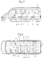
- the body of a small van is identified by 10, which is equipped with two three-seater bench seats 11, 12 for the transport of people. Access to the benches 11, 12 is through a sliding side door in the right body side wall 101.
- the rear seat 11 extends with its three seats 111-113 from one body side wall 101 to the other body side wall 102, while the front seat 12 is made narrower is so that an access 14 remains from the door opening in the right body side wall 101 to the rear seat 11 on its right side.
- the three seats 121-123 of the front seat 12 are designed to be correspondingly narrower than the seats 111-113 of the rear seat 11.
- Each seat 111-113 or 121-123 of the seats 11, 12 is equipped with a seat belt system, the seat belt systems for the seats 112 and 121 and 122 as two-point seat belts 21 and the seat belt systems for the seats 111 and 113 and close to the body wall 123 are designed as three-point belts 20.
- the seats 11, 12 are anchored in the body floor 103 and - as will be explained in detail later - can be removed from the small van without assembly tools, so that the now free area can be used as a loading area.
- a modified small van with a larger wheelbase and a longer body is sketched in a side view and a top view.
- This van is equipped with a total of three bench seats.
- the rear seat 11 corresponds to the seat of the van in FIGS. 1 and 2.
- the two seats 13 in front are the same and each have two seats, the two seats 13 abutting the left side wall 102 of the body and a wide access 14 on the right side '' from the door opening in the right body side wall 101 to the middle seat 13 and the rear seat 11.
- the width of the seats 131, 132 of the seats 13 is equal to the seat width of the seats 111-113 of the seat 11.
- Each seat 132 of the two seats 13 close to the side wall of the body is in turn equipped with a three-point seat belt 20 and each other seat 131 of the two seats 13 with a two-point seat belt.
- the two bench seats 13 are anchored in the body floor 103 in the same way as the bench seat 11. All types of benches 11-13 are assembled on the modular principle from prefabricated standard elements and have a seat frame 15 for receiving a seat cushion 16 and a backrest 17 and seat feet 18 for anchoring the seat frame 15 to the body floor 103.
- FIG. 5 the structural design of the two-seat bench 13 and in Fig. 6 the structural design of the three-seat bench 11 in the shell, ie without a seat cushion and Backrest, shown.
- the upper seat frame 15 of the seat 13 in FIG. 5 is composed of three L-shaped spars 22, four cross tubes 23 and two seat feet 18.
- the four L-shaped spars 22 are spaced apart from one another and each laterally delimit a seat 131 or 132
- the L-shape of the spars 22 can be seen in particular from FIG.
- the short leg 221 of the spars 22 extends approximately horizontally in the seat cushion depth, while the long leg 222 is inclined by more than 90 ° and extends at the backrest height.
- the total of three spars 22 are rigidly connected to one another by the four cross tubes 23, two lower cross tubes 23 being connected to the short legs 221 of the spars 22 and two upper cross tubes 23 to the long legs 222 of the spars 22.
- the two upper cross tubes 23 are guided at a parallel distance from one another and arranged at the end of the long legs 222, while the lower cross tubes 23 each run at a parallel distance from one another at the front and rear ends of the short legs 221 of the spars 22.
- the cross tubes 23 are guided through the bars 22 and welded to them.
- one seat foot 18 is assigned to a seat 131 and 132, and in the area between two spars 22 is attached to the two lower cross tubes 23 at a right angle from them and welded to the cross tubes 23.
- the three-seat bench 11 according to FIG. 6 is composed in the same constructive manner from the individual elements of the modular system or modular system, with a total of four spars 22 and three seat feet 18 being present in accordance with the increased seat 113.
- the four spars 24, which are arranged at a parallel distance from one another, are in turn rigidly connected to one another by four cross tubes 23, and the total of three seat feet 18 are each in the area between two spars 22 at the two lower cross tubes 23 set at right angles and welded to them.
- the spars 22 and the seat feet 18 each consist of two half-shells 24, 25 and 26, 27 to form hollow box profiles composed.
- the two half shells 24, 25 and 26, 27 made of high-strength steel lie on one another at their abutments with flanges 241 and 251, 242 and 252 or 261 and 271, 262 and 272 which are bent approximately at right angles, the flange pairs being shared by means of a rolling tool 28 and 29 or 30 and 31 are rolled into a rolled seam.
- roller seams 28-31 By means of these roller seams 28-31, a positive connection of the two half-shells 24, 25 and 26, 27 is achieved on the spar 22 and on the seat base 18, which makes no further work processes necessary.
- the outlay on devices and production time is less than in the case of so-called integral connections, such as those produced by spot welding and the like.
- the material accumulation in the roll seam increases the section modulus against bending and ensures a high degree of kink resistance.
- a schematically indicated belt deflector 34 for the three-point seat belt 20 is attached to the reinforcement profiles 32, 33.
- both outer spars 22 are provided with reinforcing profiles 32, 33 and a belt deflector 34 in the three-seat bench 11 according to FIG. 6.
- the outer spar 22 near the side wall is connected to the corresponding body side wall 101 and 102, respectively.
- the wall connection 35 which is shown in FIGS. 11 and 12, is of flexible design.
- the wall connection 35 consists of a tether 36 fixed to the spar 22 and a hook 37 fastened to the body side wall 101 or 102.
- the tether 36 is designed as a loop 38 which is received at the end in a bow-shaped steel thimble 39 (FIG. 12).
- the steel thimble 39 engages around a threaded bolt 40 with its two legs and is non-positively fixed on the threaded bolt 40 with a threaded nut 41.
- the threaded bolt 40 which can also be seen in FIGS. 5 and 6 and protrudes laterally from the outermost spar 22, is inserted into the open end of an upper cross tube 23 and welded to the reinforcing profiles 32, 33 (FIG. 11).
- the leg ends of the steel thimble 39 which holds the steel cable loop 38 by means of a press connection, are angled so that they point away from the outer spar 22. This angling has the advantage that, when installing the seat 11, 13, the loop 38 will automatically reach behind the hook 37 on the body side wall 101 or 102 with a high degree of probability.
- the preferably made of aluminum hook 37 is screwed to the Body side wall 101 and 102 fastened and forwards the belt forces transmitted via the spar 22, the threaded bolt 40 and the tether 36 to the vehicle body 10.
- the end of the belt at one end and the buckle at the other of the two each limit a seat Spars 22 attached so that the respective spars 22 in FIGS. 5 and 6, each associated with two seats 131 and 132 or 111 and 112 or 112 and 113, respectively, have fastening devices for a belt end and a belt buckle from two different seat belt systems carry.
- the fastening devices are not shown for the sake of clarity.
- a seat receptacle 42 fastened to the body floor 103 is assigned to each seat foot 18.
- Such a foot receptacle 42 is shown in longitudinal section in FIG. 13.
- Each foot receptacle 42 has an elongated fastening plate 49 with two depressions or troughs 43, 44 arranged at a distance from one another in the longitudinal axis of the plate, in each of which a locking bolt 45 or 46 extending transversely to the longitudinal axis of the plate is fastened, each locking bolt 45, 46 in the trough side walls is welded in.
- each locking hook 47, 48 is arranged at a longitudinal distance from one another, which protrude beyond the lower edge of the seat foot 18, so that when the seat foot 18 is seated on the body floor 103, the locking hooks 47, 48 protrude into the depressions 43, 44 and there the locking bolts 45, 46 on their from the seat base 18 overlap the opposite side.
- each locking hook 47, 48 is made up of two hook profiles 52, 53 projecting in one piece, each from the lower edge of two congruent hook strips 50, 51 extending in parallel spacing, and one of these two Hook profiles 52,53 interconnecting transverse plate 54 formed.
- the cross plate 54 is reshaped to the contour of the hook profiles 52, 53 and has a cross piece 55 which extends from the hook strip 50 to the hook strip 51 and is designed to rise at an acute angle to the hook base. If the seat with its seat feet 10 is inserted vertically into the foot receptacles 42, the crossbar 55 of the locking hooks 47, 48 hits the respective locking bolt 45, 46. The inclined position of the crossbars 55 causes the locking hooks 47, 48 to slide forward on the locking bolts 45, 46 by the weight of the seat and thus largely automatically slide the locking bolts 45, 46 into the bottom of the locking hooks 47, 48.
- a manually releasable quick release fastener 56 is assigned to the rear locking hook 47 and, as shown in FIG.
- the quick-release fastener 56 has a plunger 57 which is guided in a vertically displaceable manner and which, under the action of a return spring 58, pushes in front of the opening of the locking hook 47.
- the plunger 57 passes through an opening 59 in the crosspiece 55 of the cross plate 54.
- the plunger 57 is on the one hand by a Guide opening 60 in a connecting plate 61 and guided by a guide pin 62 extending between the hook strips 50, 51.
- the connecting plate 61 connects the two hook strips 50, 51 to one another and is welded to the upper edge thereof, opposite the transverse plate 54 of the locking hook 47.
- the guide pin 62 is arranged at a vertical distance from the transverse plate 61.
- the quick-release fastener 56 includes a hand lever 63 which is designed as a two-armed swivel lever and is pivotably held on a bolt 64 which extends between the two hook strips 50, 51. 16, the hand lever 63 is arranged on the outer wall of the seat foot 18, which is formed by the half-shell 27.
- One lever arm 631 of the hand lever 63 carries a vertically angled handle plate 65, while the other swivel arm 632 of the hand lever 63 carries a shifting lug 66, which is arranged so that it swivels clockwise against the locking bolt 45 in FIG. 13 when the hand lever 63 is pivoted strikes, namely on the rear side facing away from the plunger 57.
- a driving pin 67 protrudes from the swivel arm 631 of the hand lever 63 at right angles, which protrudes through an elongated hole 68 in the half-shell 27 of the seat base 18 and engages in a driving opening 69 in the plunger 57. 13, the plunger 57 is pushed upwards against the force of the return spring 68 by pivoting the hand lever 63 in FIG. 13 clockwise, thereby opening the rear locking hook 47 to allow the locking bolt 45 to exit.
- the quick-release fastener 56 on the seat must first be released.
- the hand lever 63 in Fig. 13 in Swiveled clockwise.
- the positions taken overall in succession by the swivel lever 63 and the quick-release fastener 56 are shown in the exact order in FIGS. 14 and 15.
- the plunger 57 is first moved vertically upward in its guides 60 and 62 and the return spring 58 is tensioned in the process.
- the sliding lug 66 on the hand lever 63 comes to rest against the locking bolt 45 (FIG. 14).
- the displacement lug 66 presses against the locking bolt 45, as a result of which the seat is moved somewhat backwards as a whole and the locking hooks 47, 48 are pushed off by the locking bolts 45, 46. If the locking bolts 45, 46 are completely pushed out of their associated locking hooks 47, 48, the displacement lug 66 is pivoted into the rear locking hook 47 at the same time. In this swivel position (FIG. 15), the hand lever 63 engages in a notch, not shown here, on the seat base 18. The seat, which is no longer secured, can be removed and removed from the foot mounts 42 by gently pulling it backwards.
- the seat 11-13 is inserted in the reverse manner.
- the seat is inserted into the associated foot mounts 42, with the quick release fastener 56 being in the position shown in FIG. 15.
- the first contact of the seat foot 18 with the locking bolts 45, 46 takes place via the inclined transverse plates 54 on the locking hooks 47, 48. Due to its own weight, the seat slides forward.
- the locking bolt 45 presses against the shifting lug 66 and forces the hand lever 63 to pivot counterclockwise in FIG. 15, as a result of which the locking lever 63 is pressed out of its catch and the return spring 58 pulls the plunger 57 vertically downward.
- the hand lever 63 is pivoted further counterclockwise via the driving opening 69 and the driving bolt 67 (FIG.
- the bench can be equipped with only one seat as a so-called single seat.
- the upper seat frame is composed of only two L-shaped bars 22, four cross bars 23 and two seat feet 18, the two bars 22 delimiting the individual seat on the left and right.
- the two seat feet 18 are placed between the spars 22 on the lower two transverse tubes 23, projecting downward at right angles from the latter, and are in turn welded to them.
Landscapes
- Engineering & Computer Science (AREA)
- Aviation & Aerospace Engineering (AREA)
- Transportation (AREA)
- Mechanical Engineering (AREA)
- Seats For Vehicles (AREA)
Applications Claiming Priority (2)
| Application Number | Priority Date | Filing Date | Title |
|---|---|---|---|
| DE19501743 | 1995-01-23 | ||
| DE19501743A DE19501743A1 (de) | 1995-01-23 | 1995-01-23 | Sitzbank für Kraftfahrzeuge, insbesondere für Kleintransporter |
Publications (3)
| Publication Number | Publication Date |
|---|---|
| EP0722855A2 true EP0722855A2 (fr) | 1996-07-24 |
| EP0722855A3 EP0722855A3 (fr) | 1996-12-11 |
| EP0722855B1 EP0722855B1 (fr) | 2001-03-14 |
Family
ID=7751985
Family Applications (1)
| Application Number | Title | Priority Date | Filing Date |
|---|---|---|---|
| EP96100584A Expired - Lifetime EP0722855B1 (fr) | 1995-01-23 | 1996-01-17 | Banc pour véhicules automobiles, en particulier pour camionnettes |
Country Status (5)
| Country | Link |
|---|---|
| US (1) | US5826945A (fr) |
| EP (1) | EP0722855B1 (fr) |
| DE (2) | DE19501743A1 (fr) |
| ES (1) | ES2156962T3 (fr) |
| PT (1) | PT722855E (fr) |
Cited By (8)
| Publication number | Priority date | Publication date | Assignee | Title |
|---|---|---|---|---|
| FR2758502A1 (fr) * | 1997-01-22 | 1998-07-24 | Faure Bertrand Equipements Sa | Dispositif d'assise pour vehicule automobile, et vehicule automobile comportant un tel dispositif |
| EP0863042A3 (fr) * | 1997-03-07 | 1998-12-30 | Ikeda Bussan Co., Ltd. | Mécanisme pour détacher un siège de véhicule |
| FR2772320A1 (fr) * | 1997-12-12 | 1999-06-18 | Faure Bertrand Equipements Sa | Siege a entraxe modulable |
| FR2775227A1 (fr) * | 1998-02-20 | 1999-08-27 | Faure Bertrand Equipements Sa | Dispositif de fixation pour siege de vehicule, siege de vehicule comportant un tel dispositif, et glissiere pour un tel siege |
| FR2779685A1 (fr) * | 1998-06-10 | 1999-12-17 | Peugeot | Agencement de siege reglable et amovible dans un habitacle de vehicule automobile |
| FR2830489A1 (fr) * | 2001-10-10 | 2003-04-11 | Productions Sa B V | Pied a structure modulaire pour siege de vehicule de transport |
| EP1440839A3 (fr) * | 2003-01-24 | 2005-08-03 | Vogelsitze GmbH | Pied pour un siège de véhicule |
| EP2670626B1 (fr) * | 2011-02-05 | 2018-07-04 | Volkswagen Aktiengesellschaft | Concept de siège à structure légère, modulable |
Families Citing this family (14)
| Publication number | Priority date | Publication date | Assignee | Title |
|---|---|---|---|---|
| FR2797233B1 (fr) * | 1999-08-06 | 2001-08-31 | Renault | Dispositif pour la transmission de signaux entre une unite de controle et de commande d'un vehicule automobile et un equipement monte sur un sous-ensemble de celui-ci |
| US6260924B1 (en) | 1999-08-11 | 2001-07-17 | Johnson Controls Technology Company | Modular seat back system |
| DE10142981B4 (de) * | 2001-09-01 | 2005-04-21 | Keiper Gmbh & Co. Kg | Lehnenpolsterträger für einen Fahrzeugsitz |
| US6752465B2 (en) * | 2002-01-30 | 2004-06-22 | Tachi-S Co., Ltd. | Seat framework for bus |
| FR2850331B1 (fr) * | 2003-01-23 | 2005-04-08 | Renault Sa | Agencement d'une rangee transversale de sieges individuels dans un habitacle de vehicule automobile entre deux passages de roue et siege lateral pour un tel agencement |
| DE102005049212A1 (de) * | 2005-10-07 | 2007-04-12 | Sitech Sitztechnik Gmbh | Gurtbaum als Modul, in einem System zur Anordnung von multifunktionalem Interieur auf einer Plattform |
| KR100747883B1 (ko) * | 2005-11-03 | 2007-08-08 | 기아자동차주식회사 | 3점식 시트 벨트의 보강 구조 |
| DE102007016690A1 (de) | 2006-10-27 | 2008-04-30 | Johnson Controls Gmbh | Strukturelement für Fahrzeugsitz |
| AU2007237155B2 (en) * | 2006-12-13 | 2012-12-20 | Styleride Pty Ltd | A Bus Module and Method |
| JP2008265523A (ja) * | 2007-04-20 | 2008-11-06 | Suzuki Motor Corp | 車両用シートの分割式シートバック取付構造 |
| WO2010126385A2 (fr) * | 2009-05-01 | 2010-11-04 | Fraser Fire & Rescue Limited | Améliorations apportées à des sièges de véhicule ou s'y rapportant |
| KR20160099657A (ko) * | 2013-12-16 | 2016-08-22 | 존슨 컨트롤스 테크놀러지 컴퍼니 | 시트 배열체 |
| DE102017011999A1 (de) | 2017-12-22 | 2018-06-28 | Daimler Ag | Halteanordnung für eine Sitzanlage eines Kraftwagens |
| US12377757B2 (en) * | 2021-09-22 | 2025-08-05 | Indiana Mills & Manufacturing, Inc. | Bus seat with self-reinforced pedestal |
Family Cites Families (16)
| Publication number | Priority date | Publication date | Assignee | Title |
|---|---|---|---|---|
| US2720914A (en) * | 1952-12-08 | 1955-10-18 | Briggs Mfg Co | Seat structure for vehicles |
| US3870363A (en) * | 1971-06-03 | 1975-03-11 | American Seating Co | Semi-cantilever twin-seat chair |
| US4229040A (en) * | 1978-11-27 | 1980-10-21 | Fairchild Industries, Inc. | Seat support structure |
| DE3022640A1 (de) * | 1980-06-18 | 1982-01-07 | Ignaz Vogel Gmbh Und Co Kg - Fahrzeugsitze, 7500 Karlsruhe | Fahrgastsitz |
| GB8331260D0 (en) * | 1983-11-23 | 1983-12-29 | Toll I C | Aircraft seats |
| DE3706395C2 (de) * | 1987-02-27 | 1995-05-24 | Teves Gmbh Co Ohg Alfred | Haltevorrichtung für einen Kraftfahrzeugsitz |
| CA1282681C (fr) * | 1987-03-13 | 1991-04-09 | Gulam Premji | Mecanisme de decrochage d'un siege |
| GB8814536D0 (en) * | 1988-06-18 | 1988-07-27 | Flight Equipment & Eng Ltd | Vehicle passenger seating |
| US4971379A (en) * | 1989-05-08 | 1990-11-20 | Hoover Universal, Inc. | Vehicle seat latch with take-up mechanism |
| FR2671002B1 (fr) * | 1990-12-27 | 1993-04-16 | Faure Bertrand Automobile | Perfectionnements aux cadres d'ossature pour dossiers de sieges et analogues et a leurs procedes et dispositifs de fabrication. |
| US5123673A (en) * | 1991-02-28 | 1992-06-23 | Hoover Universal, Inc. | Seat belt system for a vehicle seat |
| US5282662A (en) * | 1992-12-14 | 1994-02-01 | General Motors Corporation | Rear seat for all purpose vehicle |
| DE4304968C2 (de) * | 1993-02-18 | 1997-07-03 | Keiper Recaro Gmbh Co | Vorrichtung zum Verbinden eines Fahrzeugsitzes mit der Fahrzeugstruktur |
| US5393116A (en) * | 1993-10-25 | 1995-02-28 | General Motors Corporation | Van-type vehicle multi-positional seat |
| DE4408686C1 (de) * | 1994-03-15 | 1995-04-27 | Keiper Recaro Gmbh Co | Vorrichtung zum Verbinden eines Längsträgers eines Fahrzeugsitzes mit der Fahrzeugstruktur |
| US5547242A (en) * | 1995-02-10 | 1996-08-20 | Atoma International, Inc. | Latch/unlatch indicator for vehicle seat-to floor latch mechanism |
-
1995
- 1995-01-23 DE DE19501743A patent/DE19501743A1/de not_active Withdrawn
-
1996
- 1996-01-17 DE DE59606562T patent/DE59606562D1/de not_active Expired - Lifetime
- 1996-01-17 EP EP96100584A patent/EP0722855B1/fr not_active Expired - Lifetime
- 1996-01-17 ES ES96100584T patent/ES2156962T3/es not_active Expired - Lifetime
- 1996-01-17 PT PT96100584T patent/PT722855E/pt unknown
- 1996-01-23 US US08/589,065 patent/US5826945A/en not_active Expired - Lifetime
Cited By (9)
| Publication number | Priority date | Publication date | Assignee | Title |
|---|---|---|---|---|
| FR2758502A1 (fr) * | 1997-01-22 | 1998-07-24 | Faure Bertrand Equipements Sa | Dispositif d'assise pour vehicule automobile, et vehicule automobile comportant un tel dispositif |
| EP0863042A3 (fr) * | 1997-03-07 | 1998-12-30 | Ikeda Bussan Co., Ltd. | Mécanisme pour détacher un siège de véhicule |
| FR2772320A1 (fr) * | 1997-12-12 | 1999-06-18 | Faure Bertrand Equipements Sa | Siege a entraxe modulable |
| US6227595B1 (en) | 1997-12-12 | 2001-05-08 | Bertgrand Faure Equipements Sa | Seat with adjustable interval between feet |
| FR2775227A1 (fr) * | 1998-02-20 | 1999-08-27 | Faure Bertrand Equipements Sa | Dispositif de fixation pour siege de vehicule, siege de vehicule comportant un tel dispositif, et glissiere pour un tel siege |
| FR2779685A1 (fr) * | 1998-06-10 | 1999-12-17 | Peugeot | Agencement de siege reglable et amovible dans un habitacle de vehicule automobile |
| FR2830489A1 (fr) * | 2001-10-10 | 2003-04-11 | Productions Sa B V | Pied a structure modulaire pour siege de vehicule de transport |
| EP1440839A3 (fr) * | 2003-01-24 | 2005-08-03 | Vogelsitze GmbH | Pied pour un siège de véhicule |
| EP2670626B1 (fr) * | 2011-02-05 | 2018-07-04 | Volkswagen Aktiengesellschaft | Concept de siège à structure légère, modulable |
Also Published As
| Publication number | Publication date |
|---|---|
| DE59606562D1 (de) | 2001-04-19 |
| ES2156962T3 (es) | 2001-08-01 |
| EP0722855B1 (fr) | 2001-03-14 |
| US5826945A (en) | 1998-10-27 |
| PT722855E (pt) | 2001-08-30 |
| EP0722855A3 (fr) | 1996-12-11 |
| DE19501743A1 (de) | 1996-07-25 |
Similar Documents
| Publication | Publication Date | Title |
|---|---|---|
| EP0722855B1 (fr) | Banc pour véhicules automobiles, en particulier pour camionnettes | |
| DE3726711C2 (fr) | ||
| DE69408094T2 (de) | Fahrzeugsitz mit Strangpressrahmenteilen | |
| EP0765252B1 (fr) | Banquette pour vehicules a moteur, notamment autocaravanes | |
| DE4314538C2 (de) | Überrollschutz-Vorrichtung für ein Kraftfahrzeug | |
| DE102013003787B4 (de) | Fahrzeugsitz | |
| DE1082138B (de) | Verstellbarer Fahrzeugsitz fuer zwei oder mehr Personen, insbesondere in Kraftfahrzeugen | |
| DE19920536A1 (de) | Fahrzeugsitz, insbesondere für einen Lastkraftwagen | |
| DE69713209T2 (de) | Unfallsitz | |
| EP1128981A1 (fr) | Siege de vehicule dote d'une liaison a montage rapide | |
| DE29810333U1 (de) | Sitzmodul | |
| DE19800072A1 (de) | Rückhaltesystem für einen in einem Kraftfahrzeug mitgeführten Kindersitz | |
| DE2549836A1 (de) | Sitz | |
| DE69809031T3 (de) | Fahrzeugbeladungsvorrichtung | |
| EP0101073B1 (fr) | Automobile avec banquette arrière rabattable et appuie-tête réglable | |
| EP3539818A1 (fr) | Châssis ceinture pour siège de véhicule ou banquette de véhicule et ensemble de siège de véhicule | |
| EP0845385B1 (fr) | Dossier de siège arrière rabattable pour véhicules automobiles | |
| EP0646503A1 (fr) | Disposition de ceinture de sécurité pour les sièges arrières d'un véhicule automobile | |
| EP4321378A2 (fr) | Cadre pour un siège de véhicule et siège de véhicule équipé dudit cadre | |
| EP0729867A1 (fr) | Dispositif à arceau de sécurité pour véhicule automobile | |
| WO2002034564A1 (fr) | Element de reglage destine a un siege de vehicule | |
| DE102007024341B3 (de) | Fahrzeugsitz, insbesondere Kraftfahrzeugsitz | |
| EP2925561B1 (fr) | Siège de véhicule | |
| EP4098482A1 (fr) | Support de ceinture et siège du véhicule | |
| DE4345425C2 (de) | Überrollschutz-Vorrichtung für ein Kraftfahrzeug |
Legal Events
| Date | Code | Title | Description |
|---|---|---|---|
| PUAI | Public reference made under article 153(3) epc to a published international application that has entered the european phase |
Free format text: ORIGINAL CODE: 0009012 |
|
| AK | Designated contracting states |
Kind code of ref document: A2 Designated state(s): DE ES FR GB IT PT |
|
| PUAL | Search report despatched |
Free format text: ORIGINAL CODE: 0009013 |
|
| AK | Designated contracting states |
Kind code of ref document: A3 Designated state(s): DE ES FR GB IT PT |
|
| 17P | Request for examination filed |
Effective date: 19961130 |
|
| RAP1 | Party data changed (applicant data changed or rights of an application transferred) |
Owner name: PAULISCH GMBH & CO. KG Owner name: DAIMLER-BENZ AKTIENGESELLSCHAFT |
|
| 17Q | First examination report despatched |
Effective date: 19990114 |
|
| RAP1 | Party data changed (applicant data changed or rights of an application transferred) |
Owner name: PAULISCH GMBH & CO. KG Owner name: DAIMLERCHRYSLER AG |
|
| GRAG | Despatch of communication of intention to grant |
Free format text: ORIGINAL CODE: EPIDOS AGRA |
|
| 17Q | First examination report despatched |
Effective date: 19990114 |
|
| GRAG | Despatch of communication of intention to grant |
Free format text: ORIGINAL CODE: EPIDOS AGRA |
|
| GRAH | Despatch of communication of intention to grant a patent |
Free format text: ORIGINAL CODE: EPIDOS IGRA |
|
| RAP1 | Party data changed (applicant data changed or rights of an application transferred) |
Owner name: MAGNA SEATING SYSTEMS (EUROPE) GMBH Owner name: DAIMLERCHRYSLER AG |
|
| GRAH | Despatch of communication of intention to grant a patent |
Free format text: ORIGINAL CODE: EPIDOS IGRA |
|
| GRAA | (expected) grant |
Free format text: ORIGINAL CODE: 0009210 |
|
| ITF | It: translation for a ep patent filed | ||
| AK | Designated contracting states |
Kind code of ref document: B1 Designated state(s): DE ES FR GB IT PT |
|
| REF | Corresponds to: |
Ref document number: 59606562 Country of ref document: DE Date of ref document: 20010419 |
|
| ET | Fr: translation filed | ||
| GBT | Gb: translation of ep patent filed (gb section 77(6)(a)/1977) |
Effective date: 20010420 |
|
| REG | Reference to a national code |
Ref country code: ES Ref legal event code: FG2A Ref document number: 2156962 Country of ref document: ES Kind code of ref document: T3 |
|
| REG | Reference to a national code |
Ref country code: GB Ref legal event code: IF02 |
|
| PLBE | No opposition filed within time limit |
Free format text: ORIGINAL CODE: 0009261 |
|
| STAA | Information on the status of an ep patent application or granted ep patent |
Free format text: STATUS: NO OPPOSITION FILED WITHIN TIME LIMIT |
|
| 26N | No opposition filed | ||
| REG | Reference to a national code |
Ref country code: PT Ref legal event code: PD4A Owner name: DAIMLER AG, DE Effective date: 20080228 |
|
| REG | Reference to a national code |
Ref country code: PT Ref legal event code: TE4A Owner name: DAIMLER AG, DE Effective date: 20080813 |
|
| REG | Reference to a national code |
Ref country code: FR Ref legal event code: CD Ref country code: FR Ref legal event code: CA |
|
| PGFP | Annual fee paid to national office [announced via postgrant information from national office to epo] |
Ref country code: PT Payment date: 20100112 Year of fee payment: 15 Ref country code: ES Payment date: 20100125 Year of fee payment: 15 |
|
| PGFP | Annual fee paid to national office [announced via postgrant information from national office to epo] |
Ref country code: IT Payment date: 20100127 Year of fee payment: 15 Ref country code: FR Payment date: 20100223 Year of fee payment: 15 |
|
| PGFP | Annual fee paid to national office [announced via postgrant information from national office to epo] |
Ref country code: GB Payment date: 20100121 Year of fee payment: 15 |
|
| REG | Reference to a national code |
Ref country code: PT Ref legal event code: MM4A Free format text: LAPSE DUE TO NON-PAYMENT OF FEES Effective date: 20110718 |
|
| GBPC | Gb: european patent ceased through non-payment of renewal fee |
Effective date: 20110117 |
|
| REG | Reference to a national code |
Ref country code: FR Ref legal event code: ST Effective date: 20110930 |
|
| PG25 | Lapsed in a contracting state [announced via postgrant information from national office to epo] |
Ref country code: PT Free format text: LAPSE BECAUSE OF NON-PAYMENT OF DUE FEES Effective date: 20110718 Ref country code: FR Free format text: LAPSE BECAUSE OF NON-PAYMENT OF DUE FEES Effective date: 20110131 |
|
| PG25 | Lapsed in a contracting state [announced via postgrant information from national office to epo] |
Ref country code: GB Free format text: LAPSE BECAUSE OF NON-PAYMENT OF DUE FEES Effective date: 20110117 |
|
| PG25 | Lapsed in a contracting state [announced via postgrant information from national office to epo] |
Ref country code: IT Free format text: LAPSE BECAUSE OF NON-PAYMENT OF DUE FEES Effective date: 20110117 |
|
| REG | Reference to a national code |
Ref country code: ES Ref legal event code: FD2A Effective date: 20120220 |
|
| PG25 | Lapsed in a contracting state [announced via postgrant information from national office to epo] |
Ref country code: ES Free format text: LAPSE BECAUSE OF NON-PAYMENT OF DUE FEES Effective date: 20110118 |
|
| PGFP | Annual fee paid to national office [announced via postgrant information from national office to epo] |
Ref country code: DE Payment date: 20120402 Year of fee payment: 17 |
|
| PG25 | Lapsed in a contracting state [announced via postgrant information from national office to epo] |
Ref country code: DE Free format text: LAPSE BECAUSE OF NON-PAYMENT OF DUE FEES Effective date: 20130801 |
|
| REG | Reference to a national code |
Ref country code: DE Ref legal event code: R119 Ref document number: 59606562 Country of ref document: DE Effective date: 20130801 |